IEICE TRANS. FUNDAMENTALS, VOL.E102–A, NO.10 OCTOBER 2019
1383
LETTER
Phase Center Calibration for UWB Phase Interferometer Direction Finding by Virtual Baseline
Jian BAI†a),Member, Zhiqiang GE†,andLu MA†,Nonmembers
SUMMARY Phase interferometer using baseline composed by uniform linear array (ULA) with stable phase center for estimating the angle of arrival (AOA) is always employed in the direction finding (DF) system.
However, the phase center of antenna element could vary with the incident angle, frequency, multipath and so on. To deal with these problems, a novel method is proposed in this paper to calibrate the phase center over ultra- wideband (UWB). Meanwhile, the restrictions of this method are discussed.
Numerical simulations reveal that higher accuracy and larger unambiguous angle range can be obtained by the proposed method.
key words: phase interferometer, UWB, virtual baseline, AOA, the phase center, calibration
1. Introduction
Phase interferometer direction finding (DF) system with high accuracy is widely used in radar, sonar and wireless commu- nication, where phase ambiguity and accuracy are important problems that have to be addressed to determine the angle of arrival (AOA). So the researches of phase interferome- ter currently focus on algorithms of ambiguity resolution and accuracy analysis[1]–[3]. However, accurate baseline for calculating phase difference is a necessary condition for these researches. The baseline is the line connecting the phase centers of DF antennas. When the antenna phase center changes, the baseline also changes, which seriously reduces the accuracy of phase interferometer.
Schupler and others[4]first proposed to calibrate an- tenna phase center in the microwave anechoic chamber. This method is not only time-consuming and laborious, but also difficultly for implementation. Some literatures [5], [6]
have proposed detailed methods about phase center mea- surements, which also requiring adjust the location of mea- suring antenna constantly, making it very complicated and inconvenient especially in higher frequency band.
As is revealed in[8], the idea of virtual antenna with controllable location by interpolation among uniform lin- ear antenna array (ULA) is proposed to compensate for the doppler spread interference. This method is also employed in[9]to guarantee the optimal capacity of the MIMO com- munication systems. Inspired by the idea of the virtual an- tenna using interpolation with antenna array, virtual baseline with flexible length based on ULA is proposed for direction finding (DF) system using ultra-wideband (UWB) interfer-
Manuscript received December 20, 2018.
†The authors are with Science and Technology on Millimeter- wave Laboratory, Beijing Institute of Remote Sensing Equipment, Beijing, 100039, P.R. China.
a) E-mail: [email protected] DOI: 10.1587/transfun.E102.A.1383
ometer, which can almost calibrate the fluctuations of the antenna phase center and provide unambiguous AOA during detecting.
2. Virtual Baseline Algorithm
2.1 Baseline Error
Phase center is defined in the IEEE standards as: “The lo- cation of a point associated with an antenna such that, if it is taken as the center of a sphere whose radius extends into the far-field, the phase of a given field component over the surface of the radiation sphere is ‘essentially’ constant, at least over the portion of the surface where the radiation is significant.” In practical engineering, phase center offset (PCO) and phase center variation (PCV) lead to the antenna reference point (ARP), which is called as rotation center or geometrical center of antenna, deviating from the antenna phase center[6]. Analytical results show that, different fre- quencies, different incident angles, different material and multipath, all could make great influence on antenna phase center[7].
According to the above analysis, for an ULA, all the phase centers of antenna elements would deviate from their ARPs in practice. In the application of DF system, high accuracy of angle can be obtained with long baseline, thus the baseline error of ULA is determined by the antenna elements at both ends of the baseline. Now, as shown in Fig. 1, for a phase interferometer DF system equipped with ULA, and the antenna elements at both ends are marked as AandB. Suppose that the phase centers of A and B deviate from their ARPs. Assume L is the baseline determined by their ARP, andL0is the baseline of their phase centers. The baseline error is∆L0=|L−L0|. It is known that, the AOA error∆θin this ULA can be derived by the phase difference error∆ϕcaused by inner noise, the frequency error∆λand the baseline error ∆L0 as referred to in Eq. (1), where θ is the incident angle, ∆ϕis the phase difference, λ is the wavelength.
∆θ= λ
2πLcosθ∆ϕ+tanθ
λ ∆λ−tanθ
L ∆L0 (1)
Therefore, the parameter∆L0referred to in Eq. (1) de- teriorates the accuracy of phase interferometer for an ULA.
2.2 The Algorithm of Phase Center Calibration
To deal with the problem mentioned above, an interpo- Copyright © 2019 The Institute of Electronics, Information and Communication Engineers
1384 IEICE TRANS. FUNDAMENTALS, VOL.E102–A, NO.10 OCTOBER 2019
Fig. 1 Baseline error of ULA.
lation algorithm is employed to construct virtual anten- nas, and two virtual antennas make up one virtual base- line. Assume that the number of the physical antennas is N, the number of the virtual antennas is two, and the phase center coordinate of the first antenna A rray is x0. Then, the phase center coordinates of other antennas are [x0+d1,x0+d1+d2, . . . ,x0+d1+d2. . .+dN−1], where di, i = 1, . . . ,N −1, is the distance from the phase center of the i-th antenna to the previous antenna and the coordinate of the virtual antennas can be denoted by [x0+dV1,x0+dV2]T, whereT denotes the transpose and dV1, dV2 are the distance from the phase centers of the two virtual antennasV1 and V2 to x0. Let P denote the cross-correlation vector between the received signal vector r(t) = [r0(t),r1(t),· · ·,rN−1(t)]T, and the desired one r0(t)=[r00(t),r01(t)].
P=Er(t)r0(t)∗=f Pi j
g
=f
J02πid−dk
λ
g
,1≤i≤N,1≤ j ≤M (2) where J0 denotes the first-class Bessel function with zero order. It should be noted thatdi which are the phase center spacing in ULA are not constant. They vary with the change of phase center of the antenna element. Let∆didenoting the spacing error between two ARPs whose spacing ared and di. Sodi =d+∆di.
The signal of the virtual antennas r0(t)with minimum mean square error (MMSE) interpolation can be obtained by [9],[10],
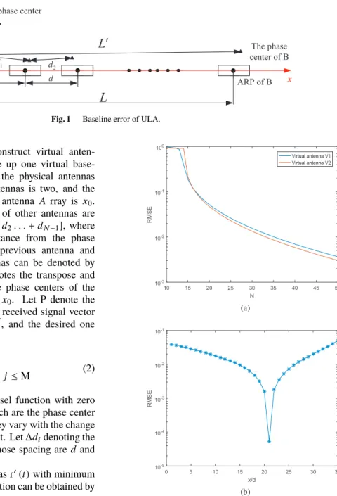
σ2min=J0(0)−PTR−1P (3) Considering a DF system withd =0.45λ [5], the pa- rameter of root mean square error (RMSE) denoted byσmin, representing the error between the signal of virtual antenna estimated by improved interpolation algorithms and the sig- nal received by real antenna in the same location, is used here to evaluate the performance of this algorithm[9],[10]. As- sume that the amplitudes of received signals are normalized, the antenna elements in ULA have the same received signal- to-noise ratio (SNR), the directions of incident waves are uniformly distributed, the frequency is 18 GHz, the number of virtual antennas is 2,d =7.5mm,∆diis Gaussian distri- bution, the probability of∆di ∈ −3σdi,3σdi is 99.74%, 3σdi =10%d,dV1 =15λanddV2 =15.5λ. The results is obtained by 1000 times Monte Carlo simulations. As showed
Fig. 2 Evaluation of RMSE. (a) RMSE with differentN. (b) RMSE with d=7.5mmandN=36.
in Fig. 2(a) where the RMSE with different number of phys- ical antennas is depicted, it can be found that the RMSE of two interpolated signals obtained by virtual antennas are all below 10−2 when N ≥ 36, and as shown in Fig. 2(b), the RMSE can be controlled less than 10−2whendV1is varying from 15dto 26d.
Therefore, two virtual antennas with flexible length can be obtained by improved interpolation algorithm. Moreover, the virtual baseline can be obtained by LV =dV2−dV1 = 0.5λ. Compared with the interpolation algorithm in refer- ence[8],[9], the improved interpolation algorithm proposed in this paper takes into account the influence of change of antenna phase center.
LETTER
1385
In this part, virtual baselineLVbased on above descrip- tion is used to calibrate∆L0to improve accuracy of AOA.
Firstly, accurate incident angleθof target can be evaluated by Eq. (4) because virtual baselineLV =0.5λcan provide unambiguous AOA. Then ϕ can be calculated by known L=(N−1)dandθ, andϕ0is measured by the baselineL0 with A and B. So∆L0can be achieved by Eq. (5),
ϕV =2πLV
λ sinθ=πsinθ (4)
ϕ−ϕ0
= 2π|L−L0|
λ sinθ=2π∆L0
λ sinθ (5)
2.3 Restrictions
The proposed phase center calibration method is restricted to the received SNR. First, the requirement for obtaining an unambiguous AOA is that the AOA error∆θVof the virtual baseline should be within a half of the maximal unambiguous angle rangeθV u as expressed in Eq. (6). And AOA error of virtual baseline is also obtained by phase difference error
∆ϕV, the frequency error∆λ and the virtual baseline error
∆Lvof virtual baselineLv, and can be expressed in Eq. (7).
∆θV< θV u
2 (6)
∆θV= λ
2πLVcosθ∆ϕV+tanθ
λ ∆λ−tanθ
LV ∆LV (7) While it is notable that∆λ can be ignored due to the fact that∆λλin Eq. (7) is too small. Assume that∆φand
∆LV are all Gaussian distribution. So the probability of
∆ϕV ∈ f
−3σϕV,3σϕVg
and∆LV ∈ −3σLV,3σLVare all 99.74%. Then, let ∆ϕV = 3σϕV and ∆LV = 3σLV, the following equation can be derived,
λ
2πLvcosθ3σϕV−tanθ
Lv 3σLV <arcsin( λ 2(Lv+3σLV))
(8) where,σϕV =p
N(2S N R), which is√
Ntimes of the phase difference error (p
1(2S N R)) obtained by single antenna element[11]. So the minimum SNR can be calculated in Eq. (9) as,
S N R>* . . . . ,
3λ√ N 2√
2πcosθLv arcsin λ
2
Lv+3σLV +3σLVLvt anθ
! + / / / / -
2
(9) Moreover, the virtual baseline error∆Lv which is dif- ferent from∆L0is determined by the RMSE of the signals obtained by the two virtual antennas using the interpolation algorithm. And, with normalized amplitude, the RMSE of signals obtained by the two virtual antennas can be derived by phase difference. Thus,σLV can be obtained by Eq. (10) as,
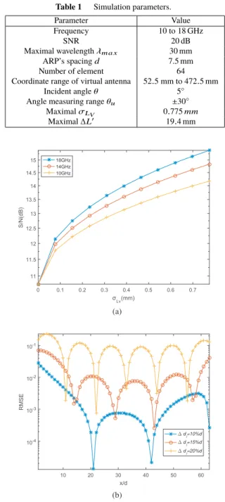
Table 1 Simulation parameters.
Parameter Value
Frequency 10 to 18 GHz
SNR 20 dB
Maximal wavelengthλm a x 30 mm
ARP’s spacingd 7.5 mm
Number of element 64
Coordinate range of virtual antenna 52.5 mm to 472.5 mm
Incident angleθ 5◦
Angle measuring rangeθu ±30◦
MaximalσLV 0.775mm
Maximal∆L0 19.4 mm
Fig. 3 Restrictions for virtual baseline. (a) required SNR with different frequenciesf=10 to 18 GHz. (b) RMSE with different∆di.
2πσLV λ sinθ≤
√2·10−2 (10)
3. Performance Evaluation
3.1 Simulation Parameters
Due to the small spacing between antennas, the mutual cou- pling among the elements cannot be neglected. Fortunately, the mutual coupling elimination method has been discussed in[8]. It will not be discussed here. The simulation param- eters are listed in Table 1.
1386 IEICE TRANS. FUNDAMENTALS, VOL.E102–A, NO.10 OCTOBER 2019
Fig. 4 Capacity with and without calibration. (a) accuracy of AOA with different frequenciesf =10 to 18 GHz. (b) angle measuring range with different frequenciesf =10 to 18 GHz.
3.2 Restrictions
As shown in Fig. 3(a), the required minimum SNR for ob- taining unambiguous AOA increases with the RMSE of the virtual baseline errorσLV and the working frequency. Also, it can be found from Fig. 3(b) that, for 18 GHz frequency, spacing error 3σdi = 10%d, 15%d and 20%d affects the RMSE of the signals obtained by virtual antennas. The po- sition range of virtual antenna decreases with the increasing spacing error when RMSE is required to be less than 10−2. 3.3 Performance
Figure 4 compares the DF performance of ULA with and without the proposed method. In Fig. 4(a), without cali- bration,∆L0of antenna elements at both ends degrade the accuracy of AOA. The larger the∆L0is, the worse the accu- racy will be. With phase center calibration, the deterioration caused by∆L0will be mitigated.
In Fig. 4(b), actual baselines are selected to obtain angle
measuring rangeθu of different operating frequencies. For example, if the operating frequency is 14 GHz, the actual baseline is 3d, which is closest to the wavelength of 14 GHz.
Without calibration, the angle measuring rangeθuis reduced with the baseline error ∆L0of actual baseline. So it is not possible to use actual baselines to obtain widely unambigu- ous angular values. With the proposed method, the virtual baseline can provide wider range.
4. Conclusion
Stable phase center is the foundation of DF system with phase interfering method. Inspired by the idea of antenna interpolation, an improved method of virtual baseline is pro- posed to obtain unambiguous AOA and calibrate the phase center of long baseline in real-time for UWB DF system.
The required SNR of this method is calculated. Simulation results reveal that higher angle accuracy and larger unam- biguous angle range for AOA measurement can be obtained compared with that have no calibration method.
References
[1] P. Janu, P. Hubacek, S. Van Doan, J. Vesely, and X.L. Tran, “Opti- mized algorithm phase interferometer ambiguity,” 2016 17th Inter- national Radar, 2016.
[2] J. Li, P.Q.C. Ly, S.D. Elton, and D.A. Gray, “Unambiguous AOA estimation using SDOA interferometry for electronic surveillance,”
IEEE 7th Sensor Array and Multichannel Signal Processing Work- shop (SAM), pp.277–280, Hoboken, NJ, 2012.
[3] H.-W. Wei and Y.-G. Shi, “Performance analysis and comparison of correlative interferometers for direction finding,” IEEE 10th In- ternational Conference on Signal Processing (ICSP), pp.393–396, 2010.
[4] B.R. Schupler, R.L. Allshouse, and T.A. Clark, “Signal characteris- tics of GPS user antennas,” J. Institute of Navigation, vol.41, no.3, pp.277–295, 1994.
[5] Z.Y. Hu, Z. Li, O. Gang, and Z. Bin, “Research on antenna phase cen- ter anechoic chamber calibration method,” 2010 International Con- ference on Microwave and Millimeter Wave Technology, pp.1522–
1524, 2010.
[6] W. Kunysz, “Antenna phase center effects and measurements in GNSS ranging applications,” 14th International Symposium on An- tenna Technology and Applied Electromagnetics & the American Electromagnetics Conference, pp.1–4, 2010.
[7] H. Qiao, F. Yin, J. Yu, C. Wang, and W. Chen, “Study on broad- band direction finding system with interferometer based on amenda- tory electric baseline,” 2016 CIE International Conference on Radar (RADAR), pp.1–4, 2016.
[8] M. Okaka and S. Komaki, “Random FM noise comensation scheme for OFDM,” Electron. Lett., vol.36, no.19, pp.1653–1654, 2000.
[9] M. Okada, H. Tokayanagi, and H. Yamamoto, “Array antenna assisted Doppler spread compensator for OFDM,” Eur. Trans. Telecommun., vol.13, no.5, pp.507–512, Sept. 2002.
[10] C. Zhang, K. Pang, and L. Ma, “Interpolated airborne MIMO antenna array,” IEEE Antennas Wirel. Propag. Lett., vol.14, pp.72–75, 2015.
[11] X. Si, J. Si, and C. Zhang, Ultra-Wideband Oassive Radar Seeker Technology, p.361, National Defense Industry Press, Beijing, China, 2016.