978-1-4244-4547-9/09/$26.00 ©2009 IEEE TENCON 2009
Proposal for a new method to alleviate traffic congestion in Wireless Mesh Network
Toyoaki Higuchi and Akira Watanabe Graduate School of Science and Technology,
Meijo University
Masashi Ito
Research and Development Center, Toshiba Corporation
Abstract— Services utilizing Wireless LANs as communication infrastructure are drawing much attention these days. However, Access Points (APs) of existing Wireless LANs are in most cases connected with wires and it is fairly expensive to install APs.
Wireless Mesh Network is one of the ways to solve this problem.
In this paper, we propose a new method to improve the communication quality of Wireless Mesh Network by having stations select the most appropriate AP according to the traffic condition of APs.
I. INTRODUCTION
Services utilizing Wireless LANs as communication infrastructure are drawing much attention these days as can be seen from the case of the technology of Wi-Fi being used not only for notebook computers and PDAs but also for cellular phones and the game machines. However, because it is common that access points (APs) of existing wireless LANs are connected with wires, the installable locations for APs are limited and also the installation costs of APs are fairly high.
Accordingly, the "Wireless Mesh Network", which connects APs of Wireless LAN by the ad-hoc network has emerged as one of the ways to solve this problem.
In the Wireless Mesh Network, it is easy for existing stations to participate in the network because the communications between stations and APs are conducted by infrastructure mode.
Thus, this system is expected to be used as temporary communication infrastructure in the cases of special events or disasters, or as communication infrastructure in areas where the costs to maintain the communication system with wires are prohibitively high.
The Wireless Mesh Network has been studied by various research institutes, and the standardization of the system is being studied by IEEE802.11 Task Group S (IEEE802.11s).
However, there are certain problems with the Wireless Mesh Network. First of all, we cannot arbitrarily modify routing protocols because the function of many of the wireless mesh networks depend on such protocols. Another problem is that seamless hand over is not possible because details of the operation of hand over have not yet been studied by IEEE802.11s. Furthermore, because multi-hop communication is performed on the same channel in the case of Wireless Mesh Network, packets tend to collide easily and the throughput could go down as a result.
We have proposed “WAPL" (Wireless Access Point Link) as one of the ways to solve the above-said problems and realized an efficient Wireless Mesh Network. The function of WAPL has already been realized independently of ad-hoc routing protocols, and we can select any ad-hoc routing protocols in accordance with our needs. We can also realize hand over without any packet loss even if end stations move, because each AP is capable of tracing the packet in communication all the time.
In this paper, we propose a new method of "improving the throughput" of Wireless Mesh Network by applying WAPL, because the degradation of the throughput is the major problem yet to be solved. Our objective is to create the situation in which more people can use the network in a more comfortable way, by alleviating the state of traffic congestion even when the communication is congested at times of disasters and special events, etc.
More in concrete, it becomes possible for newly entering stations and also for moving stations to select the most suitable AP whose traffic is not congested because APs adjust their individual signal strength of the Probe Response according to the traffic volume of the wire traffic, and thus, the communication quality of the network can be improved.
In our proposed method, stations avoid connections with congested APs as much as possible, by adjusting the signal strength of Probe Response according to the condition of their own traffic congestion. By adopting our proposed method, degradation of the throughput of the network can be avoided because stations make connections with APs by taking the state of traffic congestion of APs into account when two or more APs exist in the vicinity of the station. Our proposed method has an advantage that any additional functions do not need to be added to the station. Moreover, it is possible to apply our proposed method not only to WAPL but also to any general Wireless Meshed Networks.
Hereafter, we describe the details of WAPL in Chapter 2, existing technologies and their associated problems in Chapter 3, our proposed system based on WAPL in Chapter 4 and the results of our evaluation and consideration based on a simulation in Chapter 5, and finally, we state our conclusion in Chapter 6.
II. WAPL
A. Outline
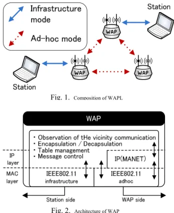
Fig. 1 shows the composition of WAPL. APs used in WAPL are called WAPs (Wireless Access Points). A WAP has two wireless interfaces. One is to communicate with stations by infrastructure mode and the other to communicate with another WAP by ad-hoc network.
Fig. 2 shows the architecture of WAP. WAP realizes all necessary functions based on applications without modifying ad-hoc routing protocols. Thus, routing protocols can be chosen freely. We have already confirmed the operability of the function of the WAP with a trial system made of a commercial AP and a PC connected with ethernet.
B. Communication method
In order to forward a packet to a targeted WAP properly, WAP generates its own LT (Link Table) that manages the corresponding relationship between the MAC address of the station and the IP address in the interface on the ad-hoc side of WAP.
When an ARP Request message is received from a station, WAP advertises the LT Generation Request message to other WAPs by flooding. In the Generation Request message, the IP address of the searched station and the IP and MAC address of the source station are described and all WAPs that receive the LT Generation Request message record the MAC address of the source station and the corresponding relationship of the IP address of the source WAP in LT. At the same time, WAP transmits an ARP request message to subordinate stations, and checks whether a targeted station exists. The WAP that has received the ARP Response message transmits an LT Response message to the source WAP by unicast. In the LT Response message, the IP addresses of the searched station and the source station, and the MAC address are described, and the source WAP, upon receipt of the LT response message, records the relationship between the MAC address of the destination station and the IP address of the destination WAP in LT. When ARP is completed, the station starts sending and receiving IP packets. The source WAP transmits the MAC frame to the destination WAP by encapsulating it with the IP address of WAP based on LT. The encapsulated packet is forwarded to the WAP that belongs to the destination station by ad-hoc routing. The destination WAP decapsulates the packet and forwards it to the destination station. If there is no communication during a certain period of time, the content of LT is deleted. Because LT is generated on-demand, the volume of the traffic by the control messages is reduced.
WAPL has a distinctive feature that enables seamless hand over whereby communication can be continued without losing packets even if the station making communication moves between WAPs. As the notification of the move of the station is made by flooding in the case of existing systems, such notification cannot be made with certainty. In the case of WAPL, however, each WAP constantly observes the packet in communication and maintains the table that records the IP and MAC addresses of the stations in the vicinity as well as the IP address of WAP. This table is called Neighboring
Communication Table (NCT). In this way, WAP always grasps the state of neighboring communications and their routes.
While it is necessary to rewrite the LT when the station moves, the source WAP retrieves the WAP that requires a correction of LT and notifies the WAT of the necessary correction. As Unicast is reliable, LT is corrected with certainty. In this way, seamless hand over with a small packet loss is realized.
III. METHOD FOR STATIONS TO ENTER THE NETWORK In IEEE802.11, two types of methods, namely passive scan and active scan, are prescribed as the methods for stations to recognize APs.
Passive scan is a method whereby AP sends Beacon signals to stations periodically and unilaterally. Although stations merely observe Beacon signals and do not respond to them, they acquire from them information required to establish a connection with the AP.
Active scan is a method whereby stations positively search APs in their vicinity. A station obtains information necessary to establish a connection with the most appropriate AP by sending Probe Request signals to APs and receiving Probe Response signals that APs send back. Then, the station is basically connected with the AP whose RSSI (Received signal strength Indicator) of the received Beacon signal or the Probe Response signal is the strongest. There occurs however a problem that even if the communication of a certain AP is congested, this very AP could be selected by the station which entered the network anew as long as the signal is strong. If that happens, then the state of communication could become worse.
Fig. 1. Composition of WAPL
Fig. 2. Architecture of WAP
In the case of Maximizing Local Throughput (MLT)[1],
the station is to decide upon the AP to be connected by guessing the throughput from the number of connected stations and the PER (Packet Error Rate). Also, the station always selects the AP whose throughput is the largest based on its own guessing even after the connection with an AP is established.
However, in the case of a method where APs are frequently changed, when a station moves between APs with different network addresses, there occur problems that it takes time to get a new IP address again and also that it is not possible to establish a connection with existing stations unless some modifications are made on the side of stations. In the case of Beacon and Probe Response signal extension method [3], the most appropriate AP is selected by the station based on the throughputs guessed based on the information such as the RSSI, PER and sending/receiving throughput of each subordinate station, which is periodically monitored by APs and stored in the expanded Beacon frame and in the Probe Respond frame. However, this method has a problem that existing stations can not establish a connection unless some modification is made on the side of stations as is the case of MLT in order to expand the Beacon and Probe Response signals, although this method does not change APs as frequently as the case of MLT.
IV. OUR PROPOSED SYSTEM
In this paper, we propose a new method by which the station can select the AP with good state of communication without making any modifications to the side of stations.
A. Outline and Composition of our proposed system
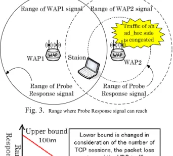
Fig. 3 shows the composition of our proposed system. It is assumed that there exists a station that is trying an entry into the network between WAP1 with a good traffic condition and WAP2 with a bad traffic condition. This Figure shows the operation of the station when it tries to enter the network anew or it moves during communication through WAPs and looks for a new WAP. The solid line in the Figure shows the range that the Prove Response signal can reach from WAP1. As regards the two types of dashed lines, the line of the inner circle shows the range which the Probe Response signal sent from WAP2 can reach, and the line of the outer circle shows the range which other signals than the Probe Response signal sent from WAP2 can reach.
The newly entring stations and the moving stations whose communication with the WAP once connected was interrupted perform channel scanning to look for a new suitable WAP in the vicinity. WAPs in the vicinity which received a Probe Request from the station send back a Probe Response signal individually. The moving stations and newly entring stations establish a connection with the WAP whose RSSI is the strongest among received Probe Response signals.
As described in Chapter 2, in the case of WAPL, WAPs always grasp the traffic condition and the packet loss rate of their own ad-hoc mode side. Based on such information, WAPs adjust the level of strength of the Probe Response according to their own traffic condition of the time when they received the Probe Request.
B. Operation of our proposed system
In our proposed system, when a Probe Request reaches from a station, each WAP replies a Probe Response with the usual signal strength in the case when its own traffic volume is small, but each WAP replies a Probe Response with a weaker signal strength in order to avoid a new station from entering the network in the case when the traffic vokume is large. With this method, the possibility of communication being conducted via the least congested WAP becomes high, and as a result, we can expect an improvement in the throughput of the system. For instance, when our proposed system is applied to the environment shown in Fig. 3, the moving station receives Probe Responses from both WAP1 and WAP2 but the station is connected with WAP1 because the signal strength of WAP1 is stronger than that of WAP2. The traffic congestion of WAP is levelized by this method, and the throughput of the network as a whole is improved.
Fig. 4 shows the relationship between the traffic congestion and the signal strength.
When the band utilization on the ad-hoc mode side of the WAP increases and the traffic congestion deteriorates, as shown by the solid line in the Figure, the signal strength of the Probe Response is weakened in inverse proportion to the traffic congestion. However, if the signal strength of the Probe Response is extremely weakened, the area where moving stations and newly entering stations are no more able to enter the network may be generated. Thus, we set a lower limit
Fig. 3. Range where Probe Response signal can reach
Fig. 4. Relation between Traffic Congestion and Signal Strength
(boundary) to the variability range of the signal strength of the
WAP so that it becomes always stronger than the signal strength of the station. Meanwhile, in the case of TCP communication, since the band utilization increases even if the number of sessions is small, it is not enough to use the traffic volume as an indicator to determine the level of the traffic congestion. Thus, we dynamically determine the lower limit of the signal strength of the Probe Response by judging the number of TCP sessions, the amount of UDP traffic and the packet loss rate comprehensively.
More in concrete, as shown in Fig. 4, the lower limit is changed in proportion as the the number of TCP sessions, the packet loss rate and the UDP traffic volume increase. For instance, in Fig. 4, the lower limit of the range that the Probe Response signal can reach fluctuates between 50 and 100 meters; in other words, the upper limit and the lower limit of the reachable Probe Response signal are 100 meters and 50 meters respectively.
Meanwhile, as regards the WAP whose signal of Probe Response is weakened recovers the signal strength in proportion as its own traffic congestion is improved. Through the above-mentioned operation, stations are connected with the WAP with the least traffic and the throughput is thus improved.
Fig. 5 shows the interactions of the WAP and the moving station in our proposed method. In Fig. 5, the interactions described here are from the point when a moving station or a newly entering station begins Channel Scanning. The moving station or the newly entering station sends a Probe Request to all channels, and checks the presence of Probe Responses.
When a Probe Response is replied, the station memorizes the signal strength. Upon completion of the Channel Scanning, the
WAP whose signal strength is the strongest from among received Probe Responses is selected and the station is connected with the WAP. The connection with the WAP is firmly established through the process of the sending and receiving of the Authentication Request /Response and the Association Request /Response between the station and the WAP.
V. EVALUATION A. Composition of the simulation environment
We evaluated our proposed system by implementing it on WAPL using a network simulator ns-2 to show the effectiveness of our proposed system, and made a comparison between the case where our proposed system is used and the case where that is not used. We adopted the value of the throughputs among moving stations as the most important evaluation item. As the indicator that shows the level of the traffic congestion, we used this time the state of traffic only.
In the case of Wireless Mesh Network, two types of interfaces, namely the infrastructure mode and the ad-hoc mode, are required in an AP. While we implemented the wireless LAN infrastructure mode in version 2.33 of the network simulator ns-2, because the version 2.33 of ns-2 which use the function of WAPL did not have the function of the wireless LAN infrastructure mode. We also made the connection between the AP and the station by independently adding to the module based on IEEE802.11 module a function to send Beacon signals as well as such functions as AP secession by the signal strength, the judgment of AP secession and re-entry, and the processing of secession/entry,
Moreover, we realized the simulation environment by directly linking internal modules of two nodes having each interface so as to have a WAP have two types of interfaces.
Fig. 6 shows the configuration of WAPs assumed in our proposed system. Each WAP is arranged in such a way that other WAPs (within the reachable range of its own signal) exist Fig. 5. Action of WAPs and entering station
Range of Signal
WAPs 100m
Stations 40m Distance of WAPs 80m Fig. 6. Arrangement of WAP assumed in the simulation
at an equal distance from the WAP to form a shape of hexagon.
Furthermore, it is assumed that the signal strengths on the infrastructure mode side and the ad-hoc mode side of the WAP are the same, and that the signal strength of all WAPs is equal and constant, and the signal wave reaches all six fixed WAPs.
In the meantime, the signal strength of the station side is sometimes set at a lower level in order to save power consumption because there are many cases where moving stations are driven by batteries. Accordingly, the signal strength of the stations in our proposed system is also set at a level weaker than that of the WAP, but the strength is assumed to be on such a level that the signal reaches at least one WAP without fail. In concrete, as shown in Fig. 6, the reachable range of the signal from a WAP is assumed to be 100 m, while the range of the signal from a station is assumed to be 40 m, and the distance between WAPs is assumed to be 80 m. In this simulation, channels used on the infrastructure mode side are made all the same.
B. Comparison of the throughputs among different stations We evaluated our proposed system by comparing it with the existing system in the network configuration shown in Fig. 7.
We arranged six WAPs at equal intervals and set up two stations (Station_C and Station_D) in a configuration where TCP communication goes through WAP_E and WAP_F as a background load. Then, we had two stations (Station_A and Station_B) that were set up for the purpose of measuring the throughput make TCP communication for 10 seconds and measured the throughput. Station_A was placed in the location slightly nearer to WAP_C between WAP_A and WAP_C.
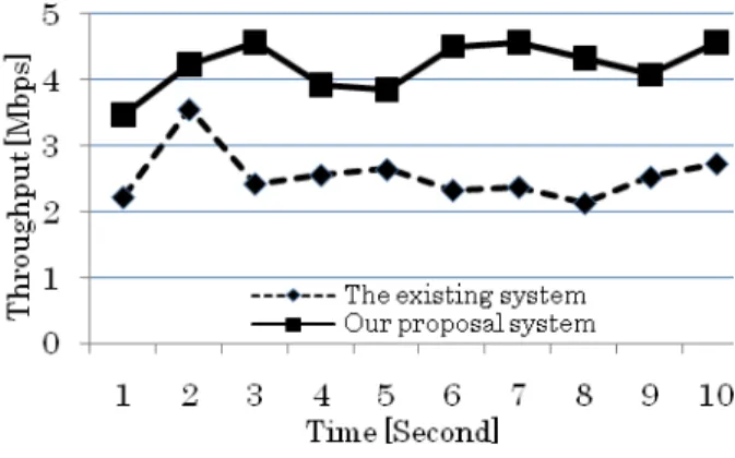
Fig. 8 shows the results of the comparison of the throughputs. The throughput of our proposed system was about 4.2 Mbps, while that of the existing system was about 2.5 Mbps. The reason for a lower throughput of the existing system is due to the fact that WAP_C received the influence of the signal sent from WAP_E that existed in the communication route between Station_C and Station_D. In the existing system, because stations are connected with the WAP whose RSSI of the Probe Response is the strongest among WAPs, Station_A is connected with WAP_C. Therefore, communication from Station_A to Station_B and that from Station_C to Station_D is done with mutual interference by WAP_C and WAP_E. In our proposed system, on the contrary, because the RSSI of the
Probe Response sent by WAP_C gets weaker, the station is connected with WAP_A whose RSSI of the Probe Response is stronger than that of WAP_C. In this way, communication from Station_C to Station_D is not interfered by the communication from Station_A to Station_B.
VI. CONCLUSION
We proposed a method whereby the state of traffic congestion is alleviated through measures in which each WAP constantly has knowledge about the state of traffic congestion of the ad-hoc mode side of itself and adjusts the signal strength of the Probe Response according to the state of its own traffic condition at the time when a Probe Request is receives, and the lowering of the throughput of the network is consequently avoided,
If the signal strength of the Probe Response from a WAP is low, the possibility of that WAP being selected by the station gets low. Thus, if the WAP whose traffic is congested replies a Probe Response with a lowered signal strength, the possibility of that very WAP being selected by the station becomes lower.
As a result, the state of traffic condition is levelized and the throughput of the network as a whole can be improved.
It was shown by the simulation that our proposed system was effective in the case of a simple network configuration. In the future, we are going to evaluate the system in a large-scale network in which communication is conducted by moving stations. We will also study the algorithm that most efficiently adjusts the signal strength of a Probe Response, by applying various kinds of parameters including packet loss rates, traffic value, the number of TCP sessions, and the volume of UDP traffic as indicators to determine the state of traffic congestion.
REFERENCES
[1] Y. Fukuda, T. Abe, and Y. OIE, “Decentralized Access Point for Wireless LANs ,” In the Proceeding of WTS 2004, SA3, May, 2004.
[2] Y. Fukuda, A. Fujiwara, M. Tsuru, and Y. OIE, “Analysis of Access Point Selection Strategy in Wireless LAN”, Technical report of IEICE.
TM , vol.104(435), pp.1-4, Nov, 2004.
[3] K. Oshima, C. Hirata, H. Watanabe and K. Suzuki, “The most suitable selection method for Wireless Access Network”, Proceedings of the IEICE General Conference, pp.584, March, 2008.
Station_D WAP_A
WAP_B
WAP_E WAP_F
WAP_C WAP_D
The communication route in proposal
system
Station_C Station_A
Station_B
The communication route in existing
system
The communication route in background
load
Fig. 7. Network configuration of simulation in throughput comparison
Fig. 8. Comparison of throughput (part 1)
[4] M. Ito, T. Shikama and A. Watanabe,” Proposal for Wireless Mesh Network that Realizes Seamless hand over and Its Simulation Results”, ISCIT, pp.-, October.2007.
[5] H. Takahashi, M. Saito, H. Aida, Y. Tobe, H. Tokuda, ”Real Environment Evaluations of a Routing Scheme Based on Estimated TCP Throughput for MANET”, Transactions of Information Processing Society of Japan, Vol.46, No.12, pp.2857-2870, Dec.2005.
[6] T. Mizobata, Y. Morioka, T. Higashino, K. Tsukamoto, and S. Komaki,
“Channel Traffic Load based Access Point Selection Scheme in WLAN Network”, IEICE technical report 108(218) ,pp.39-44, September, 2008.
[7] M. Nakamura and A. Fujiwara, “Access point selection algorithms with the minimum throughput control”, IPSJ SIG Notes 2007(23), pp.17-24, March, 2007.
[8] T. Ohyabu, Y. Fukuda, and Y. Oie, “Access Point Selection Strategy in Wireless Mesh Network”, IEICE technical report. Information networks 106(461), pp.139-144, January, 2007.
[9] Y. Taenaka, S. Kashihara, K. Tsukamoto, S. Yamaguchi, and Y. Oie,
“Implementation of Proactive AP Selection Algorithm based on Frame Retransmissions”, IEICE technical report 107(261), pp.27-32, October, 2007.
[10] MeshNetworks, http://www.motolora.com [11] IEEE802.11,
http://grouper.ieee.org/groups/802/11/
[12] Packethop
http://www.packethop.com [13] Metro Mesh
http://www.tropos.com/
[14] MeshCruzer
http://www.thinktube.com/
[15] Navda, V., Kashyap, A. and Das, S.R.: Designand evaluation of iMesh:
an infrastructuremode wireless mesh network, World of Wireless Mobile and Multimedia Networks, pp.164–170, 2005.
[16] Aoki, H., Chari, N., Chu, L. et al.: 802.11 TGs Simple Efficient Extensible Mesh (SEE-Mesh) Proposal (2005).
[17] Chen, J. and Chen, Y.-D.: AMNP: Ad Hoc Multichannel Negotiation Protocol for Multihop Mobile Wireless Networks, IEEE International Conference on Communication (2004).
[18] A.Yair, et al., “Fast Handoff for Seamless Wireless Mesh Networks”, MobiSys’06, June 19-22, 2006.
[19] N.Vishnu, et al., “Design and Evaluation of iMesh, “an Infrastructure- mode Wireless Mesh Network”,WoWMoM2005, 13-16 June 2005.
[20] Michael Bahr, “Proposed Routing for IEEE 802.11s WLAN Mesh Networks”, WICON’06, Aug 2-5, 2006.