Influence of Coupling Strength on Synchronization in Two Rings of Coupled van der Pol Oscillators
Daiki Nariai, Yoko Uwate and Yoshifumi Nishio Dept. Electrical and Electronic Eng.,
Tokushima University, 2-1 Minami-Josanjima,
E-mail: { nariai, uwate, nishio } @ee.tokushima-u.ac.jp
Abstract—In this study, we investigate the synchronization
phenomena in two rings of van der Pol oscillators coupled by resistors. We propose a novel coupled oscillatory system compris- ing two rings of van der Pol oscillators with different coupling schema. We focus on the coupling strengths of the coupled van der Pol oscillators. By computer simulation, we investigate how the synchronization phenomena change by changing the coupling strengths. In these results, we observe various synchronization phenomena.
I. I
NTRODUCTIONThe synchronization phenomena of coupled oscillators are familiar. Synchronization phenomena have been studied in various fields for many years, such as in electrical systems, mechanical systems and biological systems. Among them, the synchronization phenomena of van der Pol oscillators are similar to natural phenomena when the frequency is changed.
A coupled system of van der Pol oscillators is simple and easy to handle. Many researchers have proposed various coupled os- cillatory networks of van der Pol oscillators [1]-[3]. However, there are many portions not yet been clarified with respect to the phenomenon that the mechanism and attendant. Therefore, we investigate synchronization phenomena between two rings of van der Pol oscillators where different synchronization phenomena occur.
The van der Pol oscillator is a simple circuit. It consists of a resistor, inductor, capacitor and nonlinear resistor. It was invented by the electrical engineer Balthasar van der Pol.
The equation of a van der Pol oscillator is a second-order differential equation.
In this study, we propose coupled oscillatory system includ- ing two rings of van der Pol oscillators. The ring consists of van der Pol oscillators connected by inductors and resistors.
The phase difference of the ring depends on number of oscillators inside ring. When the number of oscillators is an odd number, the oscillators of the ring exhibit some phase synchronization. For example, five oscillators of the ring exhibit five-phase synchronization. We coupled two rings of different size by the resistor. Because we consider changes in
synchronization phenomena due to difference in circuit struc- ture, we consider two kinds of circuit structures. We consider 2k+1 - 2k +3 coupled van der Pol oscillators(k = 1, 2, 3). By computer simulation, we investigate the synchronization phe- nomena observed in the proposed circuit system by changing the coupling strengths between two rings.
II. S
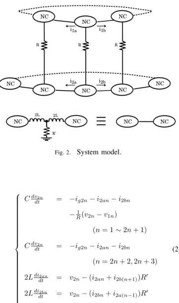
YSTEM MODELFigure 1 shows the circuit used in this study. We call this circuit NC. Figure 2 shows model of the system. We use two rings of van der Pol oscillators. The NC of the first and the second ring are connected by inductors and resistors. The first ring consist of 2k+1 NC and the second ring consists of 2k+3 NC (k = 1, 2, 3). We coupled two rings of different size by the resistors R. We observe the synchronization phenomena of adjacent oscillators. We investigate how the synchronization phenomena change upon changing the value of R.
vCn
ign
NC
Fig. 1.
The circuit used in this study.
The circuit equations of the first ring are given as follows:
C
dvdt1n= − i
g1n− i
1an− i
1bn−
R1(v
1n− v
2n) 2L
didt1an= v
1n− (i
1an+ i
1b(n+1))R
′2L
didt1bn= v
1n− (i
1bn+ i
1a(n−1))R
′.
(1)
The circuit equations of the second ring are given as follows:
- 87 -
IEEE Workshop on Nonlinear Circuit Networks December 7-8, 2018
R'
2L 2L
i2a i2b i1a i1b
NC NC NC
NC NC
NC
NC NC
NC NC NC NC
R R R
Fig. 2.
System model.
C
dvdt2n= − i
g2n− i
2an− i
2bn−
R1(v
2n− v
1n)
(n = 1 ∼ 2n + 1) C
dvdt2n= − i
g2n− i
2an− i
2bn(n = 2n + 2, 2n + 3) 2L
didt2an= v
2n− (i
2an+ i
2b(n+1))R
′2L
didt2bn= v
2n− (i
2bn+ i
2a(n−1))R
′(2)
where 1n and 2n denote the number of the circuit of the first ring and the second ring (1n = 1 2k + 1, 2n = 1 2k + 3.)
A nonlinear resistor defined as follows:
i
gn= − g
1v
n+ g
3v
3n(3)
By changing the variables and parameters as follows.
t = √
LCτ, v
n= √
g1
3g3
x
n, i
an=
√
g1C 3g3Ly
an, i
bn=
√
g1C3g3L
y
bn, ε = g
1√
L C, γ =
R1√
L
C
, α = R
′√
C L
(4)
the normalized equations of the first ring are given as:
˙
x
1n= ε(x
1n− x
31n) − y
1an− y
1bn+ γ(x
1n− x
2n)
˙
y
an= x
1n− β(y
1an+ y
1b(n+1))
˙
y
bn= x
1n− β(y
1bn+ y
1a(n−1))
(5)
and the normalized equations of the second ring are given as:
˙
x
2n= ε(x
2n− x
32n) − y
2an− y
2bn+ γ(x
2n− x
1n) (n = 1 ∼ 2n + 1)
˙
x
2n= ε(x
2n− x
32n) − y
2an− y
2bn(n = 2n + 2, 2n + 3)
˙
y
2an= x
2n− β(y
2an+ y
2b(n+1))
˙
y
2bn= x
2n− β(y
2bn+ y
2a(n−1))
(6)
where the parameters ε is non-linear strength. The parameters α and γ denote the coupling strengths of the resistor R
′and resistor R, respectively.
III. S
IMULATION RESULTSFirst, we show the simuration results of k = 1. Figure 3 shows system model of k = 1.
NC NC NC
NC NC
NC
NC NC
R R R
circuit 1 circuit 2 circuit 3 circuit 4 circuit 5
Fig. 3.
The circuit used in this study (k = 1).
The simulation results of the system model are shown in Figs.4-6. The parameters are set to ε = 0.01, α = 0.01.
We change the value of γ from 0.0000 to 0.0012 at intervals of 0.0002. We fix the value of initial value. Figure 4 shows the phase difference of the second ring. We focus on circuits connected to the first ring. When the coupling strength γ is increased, it can be observed that the phase difference of circuit 1-circuit 2 and circuit 2-circuit 3 decrease. Figure 5
- 88 -
shows the time waveform of the first ring and the second ring, in the case of γ = 0.0000. The oscillators of fist ring exhibit three-phase synchronization and the oscillators of second ring exhibit five-phase synchronization. Figure 6 shows the time waveform of the first ring and the second ring, in the case of γ = 0.0012. The oscillators of fist ring exhibit three- phase synchronization. Circuits 1, circuit 2 and cicuit 3 of second ring exhibit the synchronization similar to three-phase synchronization when the coupling strength γ increases.
Fig. 4.
Phase difference of the seccond ring (k = 1).
The first ring
The second ring
Fig. 5.
Time waveform (γ = 0.0000).
Next, we show simuration result of k = 2. Figure 7 shows system model of k = 2.
Figure 8 shows the phase difference of the second ring.
Circuits the second ring connected to the first ring exhibit the synchronization similar to five-phase synchronization when the coupling strength R increases. It is easier to observe this phenomena result of k = 1 than result of k = 2.
Finaly, we show simuration result of k = 3. Figure 9 shows system model of k = 3.
Fig. 6.
Time waveform (γ = 0.0012).
NC NC NC
NC NC
R R R
circuit 1
circuit 2 circuit 3 circuit 4 circuit 5
NC NC NC
NC NC
NC NC
circuit 6 circuit 7
R R
Fig. 7.
The circuit used in this study (k = 2).
Fig. 8.
Phase difference of the seccond ring (k = 2).
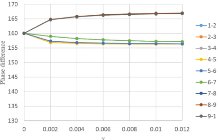
Figure 10 shows the phase difference of the second ring.
When γ is 0, circuits of second ring exhibit nine phase synchronization. Circuits the second ring connected to the first ring exhibit the synchronization similar to seven-phase synchronization when the coupling strength γ increases. Even if γ increase from 0.004 the phase difference do not change.
It is easier to observe this phenomena result of k = 1 and k = 2 than result of k = 3.
- 89 -
NC NC NC NC NC
R
NC NC
R R
R R
NC NC NC
NC NC
circuit 2
circuit 3 circuit 3 circuit 5 circuit 6 NC NC
circuit 7 circuit 1
NC circuit 9
NC circuit 8
R R
Fig. 9.
The circuit used in this study (k = 3).
Fig. 10.
Phase difference of the seccond ring (k = 3).
Circuits of the second ring connected to the first ring are affected by the first ring. When the coupling strength R increases, in the circuit of the second ring connected to the first ring, the synchronization phenomena similar to the synchronization phenomenon of the first ring exhibit. When k was large, we were able to observe the synchronization phenomena similar to the synchronization phenomenon of the first ring.
IV. C
ONCLUSIONSWe have proposed a system model using two rings of cou- pled van der Pol oscillators. We observe time waveform and phase difference with using computer simulation. We observe various synchronization phenomena by changing the coupling strengths. Circuits of the second ring connected to the first ring are affected by the first ring. When the coupling strength R increases, in the circuit of the second ring connected to the first ring, the synchronization phenomena similar to the synchronization phenomenon of the first ring exhibit. When k was large, we were able to observe this phenomena. In the future, we will investigate synchronization phenomena using other parameters and analyze the proposed circuit model.
R
EFERENCES[1] M. A. Barr´on, M. Sen, “Synchronization of four coupled van der Pol oscillators” ,Nonlinear Dynamics, pp. 357-367, June 2009.
[2] Y. Uwate, Y. Nishio and R. Stoop: Synchronization in three coupled van der Pol oscillators with different coupling strength, Proceedings of RISP International Workshop on Nonlinear Circuits, Communications and Signal Processing (NCSP’10), pp. 109-112, Mar. 2010.
[3] K. Matsumura, T. Nagai, Y. Uwate and Y. Nishio: Analysis of synchro- nization phenomenon in coupled oscillator chains, Proceedings of IEEE International Symposium on Circuits and Systems (ISCAS’12), pp. 620- 623, May 2012.
[4] H. Kume, Y. Uwate and Y. Nishio: Synchronization phenomena in different sizes of rings of coupled oscillators, Proceedings of International Symposium on Nonlinear Theory and its Applications (NOLTA’14), pp.
369-372, Sep. 2014.