Synchronization State of System Including Time Delay in One Direction
Seiya Kita
Dept. of Electrical and Electronic Eng., Tokushima University
2-1 Minami-Josanjima, Tokushima 770–8506, Japan Email: [email protected]
Yoko Uwate
Dept. of Electrical and Electronic Eng., Tokushima University
2-1 Minami-Josanjima, Tokushima 770–8506, Japan Email: [email protected]
Yoshifumi Nishio
Dept. of Electrical and Electronic Eng., Tokushima University
2-1 Minami-Josanjima, Tokushima 770–8506, Japan Email: [email protected]
Abstract—Synchronization states can be observed in coupled circuits. Further, interesting synchronization state were con- firmed in coupled time delayed chaotic circuits. In this study, we investigate the new coupled system and synchronization states observed in coupled time delayed chaotic circuits. The pattern of coupled system by time delayed chaotic circuits depends on attractor types. We focus on relationships between synchronization state and the pattern of coupling. Moreover, we investigate the specific use of time delay of time delayed circuit in this study.
I. I
NTRODUCTIONThere are many nonlinear systems containing time delay, such as neural networks, control systems, meteorological systems, biological systems and so on in the natural world.
Namely, it is considered that investigation of stability in such time-delay systems is important [1]. Generation of chaos of them all is reported self excited oscillation system containing time delay. This chaotic circuit can be easily realized by using simple electric circuit element and analyzed exactly [2].
There are examples of nonlinear phenomena, chaotic synchro- nization, clustering phenomenon and so on [3]. In particular, a number of studies on synchronization of coupled chaotic circuits have been made [4].
In this study, we investigate synchronization states by a new coupled system. The new coupled system is utilizing the characteristics of the circuit to be used in this study. By carrying out computer simulations, time delay of subcircuits effects a change synchronization state.
SW Vth
Vth
-g
-g G
C v
i
Td
L Delay Td
CC
n n n
Fig. 1. Time delayed chaotic circuit. Fig. 2. Chaotic attractor ob- tained by computer simulation.
II. T
IMED
ELAYEDC
HAOTICC
IRCUITFigure 1 shows the time delayed chaotic circuit. This circuit consists of one inductor L , one capacitor C , one linear negative resistor − g and one linear positive resistor G of which amplitude is controlled by the switch containing time delay. The current flowing through the inductor L is i, and the voltage between the capacitor C is v. The circuit equations are normalized as Eqs. (1) (2) by changing the variables as below.
(A) In case of switch connected to − g, { x ˙ = y
˙
y = 2αy − x, (1)
(B) In case of switch connected to G, { x ˙ = y
˙
y = − 2βy − x. (2)
By changing the parameters and variable as follow:
i =
√ C
L V
thx, v = V
thy, t = √ LCτ ,
g
√ C
L = 2α and G
√ C L = 2β.
the switch is connected to positive resistor DELAY
V
thtime (a)
(b)
OPERATION v
(a) v<
(b) v>
V
thtime
time V
thFig. 3. Switching operation.
- 8 -
IEEE Workshop on Nonlinear Circuit Networks December 11-12, 2015
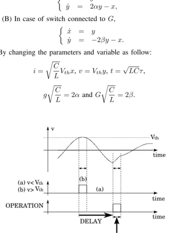
Figure 1 is chaotic attractor observed from the circuit. The switching operation is shown in Fig. 3, it controls the ampli- tude of the oscillator. This switching operation is included time delay. T
ddenotes the time delay. First, the switch is connected to a negative resistor. In state of that, the voltage v is amplified up to while v is oscillating, the amplitude exceeds the threshold voltage V
thwhich is the threshold control loop.
Second, the system memorize the time as T
thwhile v is exceeding the threshold voltage V
thand that state is remained for T
th. In subsequent the instant of exceeding threshold V
th, the switch stays the state for T
d. After that switch is connected to positive resistor during T
th. The switch does not immediately connect in the positive resistor however the switch is connected after T
d. A set of switching operations control the amplitude of v. Figure 2 shows chaotic attractor of time delayed chaotic circuit.
III. R
ING COUPLED TIME DELAYED CHAOTIC CIRCUITIn this study, we investigate the pattern of coupled three time delayed chaotic circuits. Figure 4 shows the schematic of coupled three time delayed chaotic circuits by resistors R.
By changing the parameters and variables as follows:
i
n=
√ C
L V
thx
n, v
n= V
thy
n, t = √ LCτ,
g
√ C
L = 2α, G
√ C
L = 2β and γ = R
√ C L .
In case of coupled system by resistors R, the normalized circuit equations of the system are given as follows:
(A) In case of that switch is connected to − g, { x ˙
n= y
n˙
y
n= − x
n+ 2αy
n+ γ(y
n−1− 2y
n+ y
n+1), (3) (B) In case of that switch is connected to G,
{ x ˙
n= y
n˙
y
n= − x
n− 2βy
n+ γ(y
n−1− 2y
n+ y
n+1). (4) where (n = 1, 2, 3) and x
0= x
3, x
4= x
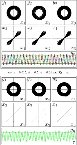
1. Figure 5 shows some of simulation results. In calculation result, in-phase synchronization state can be observed. When the coupling strength γ is large, full in-phase synchronization can be observed. However full in-phase synchronization can not be observed or synchronization is lost in case of small coupling strength γ.
Td
CC1
Td CC2
Td CC3
R
R R
Fig. 4. Ring coupled system by resistors.
IV. S
YSTEM INCLUDING TIME DELAY IN ONE DIRECTIONThe circuit in this study have characteristic time delays methods. We have devised a coupled system as shown in Fig. 6. It will be called the coupled system and ”system including time delay in one direction”
(a)α= 0.015,β= 0.5,γ= 0.01andTd=π.
(b)α= 0.015,β= 0.5,γ= 0.1andTd=π.
Fig. 5. Simulation results of ring coupled system by resistors. Attractor.
Lissajous figure. Time waveform. Red, blue and green colors denotey1,y2 andy3respectively.
Td CC1
Td
CC2
Td CC3
R
R R
Fig. 6. System including time delay in one direction.
- 9 -
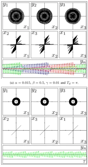
In case of the ring coupled by resistors R, such a result as shown in the Fig. 7 was obtained by difference of coupling strength γ. when the coupling strength γ is bigger then 0.1, switching synchronization state is lost and full in-phase synchronization state can be observed.
Generally switching synchronization can be observed when system including time delay in one direction is coupled by resistors R.
V. C
ONCLUSIONIn this study, we have investigated synchronization state observed some pattern of ring coupled by time delayed chaotic circuits. In case of ring coupled by resistors, we observed in-phase synchronization state. We devised a coupled system that takes advantage of features of the time delayed chaotic circuit. As a result, some special synchronization state can be observed. The switching of the amplitude of voltage in
(a)α= 0.015,β= 0.5,γ= 0.01andTd=π.
(b)α= 0.015,β= 0.5,γ= 0.1andTd=π.
Fig. 7. Simulation results of system including time delay in one direction coupled by resistor. Attractor. Lissajous figure. Time waveform. Red, blue and green colors denotey1,y2andy3respectively.