Research on the Estimation and Visualization of the shape of colonoscope in the colon
February 2013
Jaewoo Lee
Research on the Estimation and Visualization of the shape of colonoscope in the colon
February 2013
Waseda University Graduate School of
Advanced Science and Engineering
Major in Bioscience Research on Biorobotics
Jaewoo Lee
To my wife Kyungeun and My lovely kids Juhyun, Seunghyun and Junho
i
Acknowledgement
I cannot forget the day when Takanishi Sensei had finally agreed on my study at the Waseda University. Without his invitation, I couldn‟t get this great chance to study in Japan. So first of all, I would like to express my first and deep thanks to Takanishi Atsuo Sensei, who is a major advisor of my PhD thesis and professor in the Graduate School of Advanced science and engineering.
My young advisor, Dr. Ishii was a man who helped me to study on this laboratory. I was arranged in the „Jisou han‟ – autonomous colonoscope robot team in 2009. He was the leader of several teams which are working on the medical robotics related research. He was cute and spoke English fluently. I would like to appreciate on his warm mind and clear manner.
In Jisou Han, there were students who had made research at the building called „Ramducks‟
nearby the Nishi Waseda Campus. Shikanai, Ukawa and Murai were there with Gabriele from fall of 2009 to spring of 2010. I like remembering those days of Ramducks although I had a little bit suffered from difference of culture.
Nowadays I am working at the TWIns room, where I received help from Doho, Takamoto who are now a member of Jisou Han. Especially, concerning on the help of presentation of pre-public hearing, I would like to say thanks to Doho Kun on his preparation.
As my theme of research is closely related to the subject of the WB team, which is led by Dr.
Massimiliano Zecca who is Italian Professor in our Laboratory, I borrowed for the purpose of use for my research their device which had been developed through several years. With these devices, WB sensors, I could make almost all experiments that are related to the essence of research. Moreover, I learned a lot of knowledge which are necessary to my research from Dr. Salvatore Sessa, Dr. Lin, my colleague Luca Bartolommeo and Master Course student, Saito Kun lots of knowledge which are needed when I use well these devices. Especially, I would like to express my gratitude and thankful mind to Dr. Massimiliano Zecca. He was the man who I had received much of knowledge and made affect on my research life. As the device which was borrowed from his team and it would be possible for the sake of other students, I especially would like to emphasize on this point and express appreciation to him.
Dr. Salvatore was very kind when I wanted to know on how I can calculate the estimated value of the sensor signals. I would like to say thank you to Dr. Salvatore on his warm mind. Dr. Lin is the man who made Matlab code for me to do continuing research. I could not finalize my research without this valuable code. Putting my heart on this gratitude, I would like to express my thankful mind to him. Saito Kun and Tokomoto Kun were students who are kind to help me on everything
ii
what I wanted to know related to the laboratory works.
Dr. Yohan, Dr. Klaus and Dr. Seki and Mr. Wang are also colleagues who were helpful to my life in the laboratory. I would like to say thank you for them. Dr. Aiman, Dr. Hashimoto and Dr.
Nakadate were good and helpful advices by comments and email.
Mrs. Ohta san and Mrs. Itou were the ladies who had made me to control research life to be smart in Japan. I would like to express my special appreciation to them.
In Kyushu University experiments, I know that I had learned from the animal experiments with Professor. Hashizume Team. First of all, I hope to appreciate on the help on the experiments to him.
Professor Umezu has teached me on how to prepare the presentation material and checked the material in detail. I would like to express my thankful mind to him. Professor Fujie was the leader of GCOE, from which I could received my enough stipend. I could maintain my research life in Japan without any financial trouble. I hope to express my gratitude on this financial support to him.
Professor Fujimoto is the man who gave me the clue to how to approach pre-presentation easily. I know these advices made me find way to approach in the pre-public hearing. Professor Iseki made me think one more time on what is medically meaningful in my research. I would like to express my appreciation on these advices with heart.
Finally, I have to say to my wife Kyungeun my special gratitude; my graduation is due to her lo ng time service, endurance and love. Two daughters Juhyun and Seunghyun and my boy, Junho were always kind and understanding. They have always encouraged me with warm hear t and cheer when I feel hard time. Finally, I would like to express my special gratitude to my mother and brothers. I imagine that my father in the heaven, who I didn‟t s ee in 25 years ago, also would be glad to hear my news.
iii
Contents
Chapter 1. Introduction 1
1.1 Colonoscope System 2
1.2 Previous Research on the colonoscopy robot 4
1.3 Motivation and Objective of the research 17
1.4 Organization of the Paper 20
1.5 Concluding Remarks 20
I. Hardware
Chapter 2. Orientation Sensor and Sensor Network 25
2.1 Orientation Sensor Hardware 26
2.2 Shape Sensing System 29
2.3 Improvement of precision by the Kalman filtering 36
2.4 Concluding Remarks 40
II. Methodology
Chapter 3. Orientation Interpolation 43
3.1 Orientation Interpolation 43
3.1.1 Orientation Interpolation Theory 44
3.1.2 Orientation representation Method 45
3.1.3 Interpolation in quaternion sphere 47
3.1.4 Orientation Interpolation between sensors 50
3.2 Arclength Parameterization 50
3.2.1 introduction 51
3.2.2 Table building method 52
3.2.3 Approximate Integration by Newton 55
3.3 Concluding Remarks 58
Chapter 4. Kinematic Chain 59
4.1 Introduction 59
4.2 Coordinate Framework for Shape Description 60
4.3 Kinematic Chain Model in Classical Robotics Theory 61
iv
4.4 Kinematic Model in the Clifford Algebra 62
4.5 Spherical linkages 64
4.6 Concluding Remarks 72
III. Evidences, Discussion & Conclusion
Chapter 5. Experiments and Results 75
5.1 Check of the Quasi-state condition 76
5.2 Noise reduction and Improvement by filtering 77
5.3 Orientation Interpolation 83
5.4 Arclength Reparametrization 86
5.5 Serial Kinematic Chain 88
5.6 Accuracy problem 93
5.7 Discussions on Accuracy problem 95
5.8 Panoramic display for physician assistance 96
5.9 Accuracy Verification with real world data 97
5.10 Hausdorf distance 98
5.11 Calibration Target 100
5.12 Computer Simulation for accuracy test 102
5.13 Concluding Remarks 110
Chapter 6. Conclusion and Future Works 113
Appendix 117
A.1 Markov Chain Monte Carlo Method 117
A.2 Tool as a solution of Bayesian inference 118
A.3 Axis angle representation 118
A.4 Quaternion 120
A.5 Dual Quaternion and Clifford Algebra 122
A.6 Denavit - Hartenberg Representation 123
A.7 Spherical Joint 125
Bibliography 127
List of Publications 141
v
Table of Figures
Figure 1.1 Lower intestine of Human 2
Figure 1.2 Modern Colonoscope ( Olympus Co., ltd, Japan) 2
Figure 1.3 Colon viewed by the colonoscope 3
Figure 1.4 Biomechanical Model of interaction 5
Figure 1.5 Test of characteristics of colon 6
Figure 1.6 Experimental Device which can measure friction force 6
Figure 1.7 Biomechanical Model of Pig colon 7
Figure 1.8 Dynamic frictions acting on the robot 8
Figure 1.9(a) Distance – Time relation of dead pig case 9 Figure 1.9(b) Distance – Time relation of simulation model 10
Figure 1.10 Reverse screw type of robot 10
Figure 1.11 Colonoscope robot which have crawling mechanism. 11
Figure 1.12 Robot Controller for driving motors 12
Figure 1.13 Colon control: control is carried out through program 13 Figure 1.14 Control strategy which was implemented on the robot 14
Figure 1.15 Reinforcement learning algorithm 14
Figure 1.16 Performance of robot 15
Figure 1.17 Medical Image processing 16
Figure 1.18 colon boundary evaluation using active contour algorithm 17
Figure 1.19 Time to go from the anus to appendix. 18
Figure 1.20 Appearance view of the magnetic sensing system 19 Figure 1.21 Conceptual Sketch of the New Colonoscope Tube 21
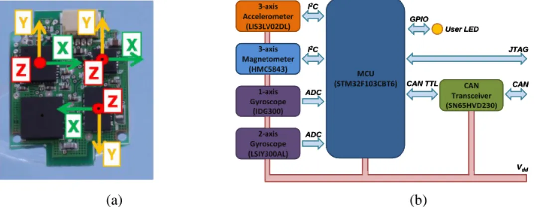
Figure 2.1 WB-3 ; the appearance of sensors 26
Figure 2.2 single chip packages of accelerometer and magnetometer pair. 28 Figure 2.3 Schematic diagram of the Orientation Sensor Unit 29 Figure 2.4 Orientation coordinate frame of the sensor 30 Figure 2.5 Rotation expression by Axis angle representation 32
Figure 2.6 Structure of the sensor network 35
Figure 2.7 Configuration of the communication method 36
vi
Figure 2.8 Configuration of whole data flow between the sensor network and algor ithm
37
Figure 2.9 Structure of Kalman filtering algorithm 39
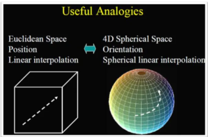
Figure 3.1 Analogies between quaternion space and Euclidean space of position 47 Figure 3.2 Sensor coordinate framework on the colonoscopy 47 Figure 3.3 Linear interpolation between starting point and ending point in quaternio n sphere
48
Figure 3.4 q1, q2are two points on the sphere 49
Figure 3.5 Bezier interpolation on 4D unit quaternion sphere 49 Figure 3.6 Joint Link pairs showing how to calculate the position vector 51
Figure 3.7 Two parametric curves. 52
Figure 3.8 method to build look up table between arc length and parameter values 54 Figure 3.9 Algorithm to calculate the arc length by Newton – Raphson 56
Figure 4.1 Relationship between Arclength framework and Euler angle in the Frene t-Serret coordinate framework
60
Figure 4.2 Sensor arrangement on the colonoscope 61
Figure 4.3 Kinematic chain model of the colonoscopy with sensor 62
Figure 4.4 Kinematic chain 63
Figure 4.5 Local coordinates for serial chains 66
Figure 5.1 Effect of the external acceleration 76
Figure 5.2 Filtering Performance of x component of Accelerometer Signals 78 Figure 5.3(a) Roll Pitch and Yaw angle change with motion of colonoscopy 79 Figure 5.3(b) Roll Pitch and Yaw angle estimation with noise filtering 80 Figure 5.4 Euler Angle(roll pitch yaw) change with time and sensor No. after Exte nded Kalman filter implementation
82
Figure 5.5 Result of rotation interpolation 84
Figure 5.6 orientation interpolations on the unit quaternion sphere 85 Figure 5.7 Numerical examples on how to use this table 86 Figure 5.8 Inverse calculation from Arclength to parameter value 87 Figure 5.9 simulation test for validating table lookup method 88
vii
Figure 5.10 Numerical Calculation for validating dual quaternion based kinematics 89
Figure 5.11 Experimental system of sensor network 90
Figure 5.12 Trajectory of sensors; No.2 and No.7 are followed 91 Figure 5.13 Trajectory of the sensor network along the time step 91
Figure 5.14 Markers on the WB sensor units 92
Figure 5.15 Experimental Setup for precision comparison between gauge and devel oping system
93 Figure 5.16 Comparison between simulation result, Optotrack estimation result and real shape
94 Figure 5.17 Precision test by comparison of simulated points and true points on th e sine curve
95 Figure 5.18 the effect of number of sensors in the network on the performance 96 Figure 5.19 visualization of the shape of the colonoscope 98 Figure 5.20 Trend of Hausdorf distance when number of link in the kinematic chai n model increases; test range between 100 and 1,000
99 Figure 5. 21 Experimental setup for real world verification 100 Figure 5.22 predesigned direction of sensors are marked 101 Figure 5.23 interpolation between two points by Bezier interpolation method 103 Figure 5.24 relation between 2 point interpolation and multipoint interpolation 104 Figure 5.25 Trouble Point, Shape can be distorted due to bad interpolation 105 Figure 5.26 interpolation of orientation by SQUAD algorithm 105 Figure 5.27 resulting shape reconstructed using kinematic serial chain model 106
Figure 5.28 curve on the 4D sphere 107
Figure 5.29 quaternion interpolation by SQUAD algorithm 108 Figure 5.30 Orientation variation of the orientation 108 Figure 5.31 smoothness effect on the orientation variation 109
Figure 5.32 True curve and Simulated curve 110
Figure 5.33 curve reconstructed from sensor data 110
Figure 5.34 Result for shape estimation as number of link increase 111
Figure 6.1 Concept diagram showing the possible layout of the endoscope handling system
114
viii
List of Tables
Table 2.1 IMU characteristics 27
Table 2.2 Sensors Characteristics 28
Table 3.1 Look-Up table for parameter and its Arclength 53
Table 5.1 condition of simulation test 83
Table 5.2 Key-points on the interpolating curve 84
Table 5.3 Test condition ; sensor location and orientation 101 Table 5.4 simulation condition for curve reconstruction 103
ix
Symbols and abbreviation
Symbols Meaning
𝐴 𝑧 , 𝐵 𝑧 , 𝐻 𝑧 z transfer function for digital filter
θ, ∅, ψ Roll, pitch and Yaw angle (degrees, radians) ax, ay x and y components of gravitational acceleration 𝑥𝑡+1, 𝑥𝑡 State vector at time step t+1,t
A,Q State transition matrix, process noise model 𝒩(𝜇, 𝜎2) Normal distribution with mean 𝜇 and variance 𝜎2
𝑥 0 Initial state
𝑃0 Initial covariance
𝑥 𝑘− Estimated value of state based on prior 𝑃𝑘− Estimated value of covariance based on prior
𝐾𝑘 Kalman Gain at time step k
𝑥 𝑘 Posterior state after updating using measurement
𝑃𝑘 Posterior covariance
ℝ3 Euclidian 3 dimensional space
𝑂, 𝑂′ Origin of body coordinate frame
𝜃 ∈] − π, π] Angle of rotation in chapter 3
𝑞 = 𝑠, 𝑥, 𝑦, 𝑧 Quaternion: s scalar part ; x, y, z = vector part
𝑞 Norm of quaternion
𝑠𝑙𝑒𝑟𝑝 𝑞1, 𝑞2, 𝑢 Spherical linear interpolation between 𝑞1, 𝑞2
𝑢 Parameter in parametric form of curve
𝛷 Generalized angle representation in chapter 4
< 𝜙𝑟 𝑠 , 𝜙𝑝 𝑠 , 𝜙𝑦 𝑠 > Roll, pitch and yaw component of generalized angle in ch apter 4
𝑠 = 𝑠1, 𝑠2, … , 𝑠𝑛 Sensor position in chapter 4
𝑄 𝑢 = (𝑄𝑥 𝑢 , 𝑄𝑦 𝑢 ) Parametric form of planar curve, u is parameter 𝑄𝑥, 𝑄𝑦 are x, y components of curve
𝐿 = 𝑑𝑃 𝑑𝑢
𝑢2
𝑢1 𝑑𝑢 Arc length of curve between 𝑢1 𝑎𝑛𝑑 𝑢2
𝑓 𝑥 𝑑𝑥 ≅ 𝑤𝑖 𝑛
𝑖=1 1
−1 𝑓(𝑥𝑖) Approximation of integration by summation of weight mul tiplied by Gaussian quadrature
x
𝐿 = 𝑤𝑖
𝑛
𝑖=1
𝑓(𝑢𝑖) Arclength approximated by the summation of weight multi plied by Gaussian quadrature
𝑀 𝑡 Difference between theoretical and real length 𝑡𝑛+1, 𝑡𝑛
𝑇𝑖 𝑢 Chevyshev polynomial
xi
抄 録
大腸がんをはじめとする消化器系がんの早期発見,早期治療には内視鏡検査が有用である.
消化管内視鏡検査は,イメージセンサー(CCD)や光ファイバーと柔軟な構造をもった チューブ状の軟性内視鏡を口腔または肛門から消化管内に挿入することで内部の様子を 鮮明な画像で、リアルタイムにモニター表示することができる.軟性内視鏡は,20世紀 前半に開発されて以来,さまざまな改良がおこなわれ,今日ではもっとも重要な医療検査 器機の一つになっている.消化器内視鏡検査の中で,大腸内視鏡検査はもっとも困難な手 技とされている.大腸に限らず消化器の形状は,体外から直視することができない.大腸 内視鏡検査において術者は,大腸の正確な形状に関する情報が得られない状況下で,大腸
軟性内視鏡を肛門から挿入し,肛門から大腸(結腸と直腸)全体を観察することが求めら れる.その際の合併症のリスク,患者のうける苦痛の程度,検査に要する時間は,術者の 技量に大きく依存する.
医療の現場では,技量の依存性が低い誰でも簡便にあつかえる軟性内視鏡のニーズがあ
り,ロボット工学や医用工学の分野では,自律的に腸内を移動するロボット型内視鏡に関 する多数の研究がおこなわれている.大腸内視鏡検査において高い技術が求められる理由 は,腸管の特性や配置に起因する.腸管は弾性と粘性のある組織で構成されており,軟性 内視鏡から力が作用することで伸展や屈曲が生じる.また腹腔内において腸管は,折りた
たまれたように配置されている.一方術者は,内視鏡の先端部の動作と体外に残された軟 性内視鏡の出入操作によって,腸管内で内視鏡を任意の位置に移動することが求められる.
例えば先端を曲げた状態で,軟性内視鏡を押し込むことで湾曲部を前進したり,内視鏡を 回転したりすることで3次元的な湾曲部を無理なく通過させる.これらの手技を状況に応 じて適切に切り替えることで,内視鏡を肛門から結腸へ進める.この際,術者が気付かな いうちに体内で軟性内視鏡および腸管がループの形成してしまう場合がある.このような ループが発生すると,肛門から内視鏡を押し込んでも内視鏡先端は前進せず,ループの径 が増大する状態に陥ってしまう.これは腸壁穿孔につながる非常に危険な事態である.一 方,ループが発生してもそれを解除する内視鏡の操作を行うことで,容易にループを直線 化することが可能である.そこでループが発生した際,術者がそれを可視化できれば,前 述の腸壁穿孔のリスクを大きく低減することができる.このような考えから,大腸内での 内視鏡の形状を計測し,それを術者に提示することで医療事故を防ぐシステムが求められ
xii
ている.
本博士論文研究は,大腸内での内視鏡の形状を可視化し,術者に提示する手法の開発を 目的としている.本研究では可視化の手法として,超小型の姿勢センサノードを内視鏡に 多数装着し,それらによって得られる情報から内視鏡の形状を推定する方法を提案してい る.各姿勢センサノードは,MEMS(Micro Electro Mechanical System)技術によっ て作製された3軸加速度センサ,3軸ジャイロ,3軸地磁気センサからなる.本博士論文で は,これらのセンサノードのハードウェアおよびセンサのデータから内視鏡の姿勢を推定 する手法について述べている.
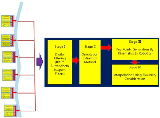
本研究は大きく分けて4つの要素から構成される.第1の要素は,センサノードの構成 およびデータ処理である.各センサノードは,3軸加速度センサ,ジャイロ,地磁気セン サからなり,これらの3種類のセンサの情報を融合させることで,センサノードのpitch, roll, yawの3軸の姿勢角を推定し,出力する.大腸内視鏡検査における術者の内視鏡に対 する操作は,比較的ゆっくりとしたものが多く,内視鏡に生じる速度変化も低いと仮定し て扱うことが可能である.温度などによるドリフトなどのノイズについては,フィルタリ ング処理によって除去している.複数のセンサから得られる時系列データに対して,カル マンフィルタを適用することで,高精度な姿勢角推定を実現している.
第2および第3の要素は,内視鏡のモデリングとモデルにもとづく内視鏡の形状推定で ある.本研究では内視鏡の構造を直列接続された剛体リンクとしている.内視鏡の形状を 推定する際は,各リンクの姿勢角,およびその変化が非常に重要であり,深く検討してい る.工学では剛体の回転をオイラー角の変化として表現し,数学的に扱う手法がとられる.
オイラー角による回転表現の短所の1つは特異点問題にある.本研究では,特異点を回避 するために,四元数が用いられている.四元数は剛体の回転やその補間に有用なため,ア ニメーションやCGの分野でよく用いられている.Shoemakeらの研究を参考に,本研究 ではベジェ曲線のためのde Casteljauアルゴリズムを用いて,3次元スプライン補間を単 位四元数に適用している.
これに加えて,ユークリッド空間におけるセンサノード間の距離についても検討してい る.センサノード間の距離は既知であり,ユークリッド空間内で表現可能である.これに もとづいて,軟性内視鏡の幾何学モデルを構築している.その後,2つの視点からその幾 何学モデルの順運動学的解法について検討している.初めには古典的なD-H表記法につい
xiii
て述べている.次に、アニメーションやCGに関する研究で用いられているスクリュー理 論を用いた解法について述べている.スクリュー理論では,一般に二重四元数を用いて表 現される.二重四元数はクリフォード代数に基づいているため,クリフォード代数につい ても記している.本研究ではクリフォード代数を用いることで,統一解的枠組みの中での 姿勢の補間および剛体リンクに関する諸問題の解を得ている.
第4の要素は,構築した手法の妥当性の実験的検証である.本研究では2つの実験が行 われている.第1の実験では,センサノードの数と推定される内視鏡の形状の精度に関す る検討がなされている.実験の結果にもとづき,姿勢補間が必要な理由についても検討が なされている.第2の実験では,推定された内視鏡の形状と実際の内視鏡の形状の比較が 行われている.さらに,推定された形状の描画方法についてもここで述べられている.こ こでは,これらの実験にもとづき,提案する手法の有用性と問題点に関する検討がなされ ている.
提案する手法を臨床で使用可能な機材に実装するためには,センサノードの小型化が必 要不可欠である.これについては,MEMS技術の進歩により,数年のうちに実現可能と見 込まれる.センサノート―の小型化が実見されれば,本研究で提案されている手法の実用
化が大いに見込まれる.さらに本研究で提案している手法は,3次元マウスなどの新たな マンマシンインターフェースにも応用可能である.デザインやアニメーションなどの分野 において,3次元マウスの登場が切望されており,本研究で提案する手法は3次元的な曲 線を作成する新しいインターフェースに応用可能である.また本研究で提案する手法は,
機械の大規模変形の計測にも応用可能である.大型の工業機械や航空機,大型望遠鏡など の光学機器のたわみやひずみの計測への応用の可能性がある.
以上のように,本論文は,直視が不可能な大腸内の軟性内視鏡の形状を推定し,可視化 する手法について詳術されている.内視鏡の可視化技術は臨床医学においてその実見が強 く求められており,本研究の成果の社会的意義は大きい.また,柔軟体の変形に関する検 討は機械工学における重要な問題領域の1つと認識されている.さらに本研究は柔軟体の 計測技術に深く関連している機械工学のみならず計測工学の発展にも貢献するものであ る.よって,本論文は博士(工学)の学位論文として価値あるものと認める.
xiv
Abstract
Colonoscopy is pre-requisite device to inspect colorectal decease. The history of colon oscopy and endoscopy goes to the early of last century. As these two devices are same pr actically in functionality, colonoscopy only is dealt with hereafter. Colonoscope is the med ical device with which physicians investigates suspicious lesions of patient‟s lower intestina l bowel and makes operation for removing polyps or deceased lesion. After it was develop ed, it had been used and improved with many people since that time. At present days in the clinic, it became prerequisite medical device in detecting decease of the digestive syst em of human being.
Modern commercialized colonoscope has various functions as a medical device. Comm ercial colonoscope has two major functions; one is function for detecting deceased lesions in the digestive system. Another major one is function for making operation such as rem oving polyps, suturing. For the purpose of the detection of decease, it has camera at the d istal tip, light source to brighten the object. For the purpose of making operation, it has v arious type of forceps, snare. Besides, it has water and air ways for cleansing and balloon ing.
Although its function is reliable and convenient to handle, the main demerit of endosc ope is that it requires elaborate skill to handle smoothly and it takes long time and abund ant experiences to get skilled with endoscope. The time to take endoscopy is inversely pro portional to the inconvenience of patients and physician himself/herself together.
Modern science and technology is integrated to this medical device. Although modern colo noscopy has state-of-the-art technology in its own, desire to make better convenient and m ore functional device demands additional research. With the advance of technology in robo tics area, the automation and robotization of colonoscopy has also been studied during past decades.
Even though commercial colonoscope system has long time history of development and im provement on its performance until now, endeavourers to the more convenient and easy to operate system is still going on. In recent days, one of main trends on the direction of d evelopment of the colonoscope system is automation and application of robotics technology.
Commercial colonoscope system has a lot of function which can detect inflated lesion an d make suitable operation in case of necessity. All the things such as manipulation are car ried out by the physician. In other to reduce physical work and concentrate on the mental
xv
and medical work. The complexity of skill comes from the characteristic of the intestine.
Upper intestine has the form of long thin flexible and multiply bended tube. Specially, lo wer intestine is severely folded. In order to make endoscope forward in the lower intestine, the stretching behavior of folded section is needed to go smoothly.
With this reason, flexibility of endoscope is prerequisite characteristics. But this flexibility of material of endoscope also becomes a cause of increases of complexity in skill in hand ling the endoscope. Physician carries out behaviors such as pushes, pulls or twists with gr asping body of endoscope at the entrance such as mouse or anus. In some case, even pus hing endoscope, it doesn‟t move forward. This phenomenon is called “looping”. Once loop is formed, the endoscope is not moved forward inward the lower intestine, even though physician pushes it at the entrance. This complexity can be reduced when the shape of th e endoscope in the colon is provided. One of the important functionality that in near fut ure has to be accomplished in this area is the development of visualization of shape of co lonoscopy while operating on the colon. Physicians usually sees monitor displaying the vie w of colon which comes from the camera attaching on the distal tip of endoscopy/colonos copy.
The purpose of this research is to develop the methodology which can visualize the vivid shape of the colonoscope that is moving in the colon by the manipulation of physician an d to provide the physician the suitable information which is processed optimally to the ph ysician. In this paper, visualization method on the shape of the colonoscope when it is i n the colon of the patient is presented with the detailed hardware and methodology. As se nsing nodes for visualization, a number of orientation sensors, which consists of 3 axis of accelerometer, 3 axis of rate gyroscope and 3 axis of magnetometer, are used. Due to th e MEMS (micro electro mechanical system) technology, orientation sensors are produced m assively, resulting in low cost and smaller. With these sensors by the form of network, I t ry to approach this problem.
The proposed methodology consists of 4 major parts. Among them, first one is for t he hardware which receives raw signals to evaluate Euler angles or roll, pitch and yaw an gle. Quasi static situation is assumed in the accelerometer signals. In reality, physicians d eals with colonoscope gently and smoothly with low movement speed, this assumption ma kes sense. Noise filtering is carried out in advance to reduce the level of noise, which co mes from the source such as drift and temperature. As time changing data are dealt with
xvi
here, sensor fusion technique such as Kalman filtering is also checked as a method to imp rove the accuracy of the sensor node.
The other 2 parts concerns on methodology: orientation interpolation, Arclength Repar ametrization and modeling and analysis by using serial kinematic chain. As orientation of rigid body in the space is represented by rotation angles such as Euler angles, study on th e rotation is deeply discussed. Rotation constitutes the special orthonormal group (abbreviat ed as SO (3)). Unlike points in the Euclidian space, rotation does not commute on the m ultiplication in the SO (3). Euler angles are widely used for representing rotation. It is als o easy to access. Main drawback of Euler angle representation is singularity which is also called Gimbal lock. In order to avoid singularities, quaternion representation is checked.
Quaternion works well in dealing with rotation operation.
Firstly, orientation interpolation in the quaternion unit sphere is described. As quaternion w as a good descriptor to express rotation of body, orientation interpolation using quaternion had been used in the game and animation community. From the cornerstone paper of Ken Shoemake (1985), a lot of research had been carried out. Here with de Casteljau algorith m for Bezier curve, 3 dimensional spline interpolations are implemented on the quaternion unit sphere.
Additionally, secondly, the obtaining the length of the distance between sensors using Eucl idean coordinates is studied. As the distance between sensors was known along the Arclen gth, this value should be known within the framework of Euclidian coordinates. Table loo kup and Newton Raphson method is explained.
Finally, Kinematic chain model is described. Shape is approximated by the serial kinematic chain model. Well known forward kinematics model is described in detail in two points of view. First of all, classical method such as D-H method is expounded. In addition, as shape can be described by a particle moving in the 3 dimensional space, screw theory - rigid body motion theory – which was widely been studied in the area of computer anima tion and robotics discipline is implemented. As long as screw theory concerns, dual quater nion representation is essentially used. As dual quaternion lives in the Clifford algebra, Cli fford algebra is inevitably introduced. With introducing Clifford algebra or recently named as Geometry Algebra we can solve this problem which constitutes orientation interpolation and kinematic chain in the consistent and unified solution framework.
Final part includes abundant experimental evidence: two kinds of experiments are carried out. Accuracy problem is firstly handled with the number of sensors in the network. This
xvii
also explains why orientation interpolation is needed in this method.
Secondly, comparison between true curve and generated curve by this method is performed.
Finally, the visualization is implemented with real data. These shows up that problem are remained yet. With some simulation experiments, this method shows its suitability for esti mating shape of the colonoscopy. Even though sensor which is suitable to the small sized space of modern colonoscopy was not yet developed, it will be finally developed in the near future as MEMS technology and related semiconductor industry are growing prospero usly. At that time, this method will receive spot light on commercialization at the industri al and medical fields.
Moreover, this technique does not confine its usage in the range of medical application: it can extend its utility to the area of special gesture recognition such as spatial mouse. Sp atial mouse is one of very useful device which can draw pictures on the computer monito r only by moving PC-like cellular phone. Also as a major application, measuring system for detecting large deformation in the huge structure is another potential application field.
In the huge equipment field such as turbine, airplane or astronomical electromagnetic tele scope, this technique can play a major role for measuring dynamic deformation.
.
Chapter 1. Introduction
1
Chapter 1
Introduction
1.1 Colonoscope system
1.2 Previous Research on the colonoscopy robot 1.3 Motivation and Objective of the research 1.4 Organization of the Paper
1.5 Concluding Remarks
In this paper, as an important functionality of colonoscopy, I deal with the visualization method of its shape during operation. Colonoscopy is a medical device which can detect the infected lesion: tumour or polyps which can be a cause of colorectal cancer in the fut ure [1]. Before I step into main dish, I will introduce in this chapter how the colon is lik e, why colonoscopy is important and how was the history of development, which dates to the previous century. Moreover, I will talk about the prospect of the future of colonosco py after reminding ourselves of what kind of things we has contributed on this interesting subject.
Medical diagnosis has its role as a vital step to find its cause of decease before procee ding to the step of curing decease in entire medical work. In the decease on the digestive system of human, the medical device called endoscope had been used since 1900.
Colon is an organ of human body. It is a part of the digestive system of human as sho wn in figure 1.1. Unlike other organ, digestive system is open to the outside through mou se and anus. Digestive system is divided into upper digestive system and lower digestive s ystem. Colon is a part of lower digestive system. As in figure 1.1, colon consists of sigm oid colon, descending part, transverse part and ascending part and cecum. Finally it is con
Chapter 1. Introduction
2
nected through rectum to anus.
Figure 1.1 Lower intestine of Human
1.1 Colonoscope system
Colonoscope can be a system, not simple device; at least I would like to call it as a „s ystem‟. In engineering site, system means assembly which compose of functional element.
Colonoscopy can also be called by system in this aspect. Modern colonoscopy usually con sists of colonoscope tube, video processing unit, specially made lighting unit, suction pump, monitor and cart. In addition, it has lots of accessories such as various kinds of forceps.
Forceps are important tools which are used to remove or grasp inflected lesion.
Figure 1.2 Modern Colonoscope ( Olympus Co., ltd, Japan)
Chapter 1. Introduction
3
History of the colonoscope [1]
Although the first telescopes were developed in Europe in the early seventeenth century, it was Philipp Bozzini who first tried to observe inside the human body, through a rigid tube without optics. He developed an apparatus called the light conductor in 1805, which he used in his attempt to observe rectum, larynx, urethra and upper oesophagus.
In 1826, Segales in France reported on a new method for examining the human bladder u sing a funnel-shaped metal tube, with a concave mirror and a candle light source. In 1853, Desormeaus in France developed the first instrument of clinical value, primarily for diagn osis and treatment of urological disease, and called it the “endoscope”.
The endoscope comprised a viewing tube and a light source unit, a “gazogene” lamp lit by a mixture of alcohol and turpentine. The viewing tube, at its junction with the light s ource, had an angled mirror with a small hole in the centre.
Drawback of modern commercial colonoscope system
Even though commercial colonoscope system has long time history of development and improvement on its performance until now, endeavourers to the more convenient and easy to operate system is still going on. In recent days, one of main trends on the direction of development of the colonoscope system is automation and application of robotics technolo gy. Commercial colonoscope system has a lot of function which can detect inflated lesion and make suitable operation in case of necessity. All the things such as manipulation are carried out by the physician. In other to reduce physical work and concentrate on the men tal and medical work
Figure 1.3 colon viewed by the colonoscope
Chapter 1. Introduction
4
1.2 Previous Research on the colonoscopy robot
Until now we has long time been focusing ourselves to the realization of new concept of colonoscopy in which our robot technology is melted down to be autonomous colonoscopy robot[37]. Autonomy of colonoscopy by using robot and related technology is key essenc e in our research[38-44]. In the automation of colonoscopy, one of the important and maj or trends is the introduction of robotics technology to increase the performance of the col onoscopy. This trend is going to the various directions. The major issues are as follows.
The biomechanical model of the colon
Automatic locomotion in the colon
The sensing system in the colon
Detection of lesion which has decease such as tumor or infection.
Simulator for training of novice doctor in medical education[33-35]
Each of the above subjects is ones which have broad spectrum of issues. In the following, each of the suggested issues are investigated and discussed.
The biomechanical model of the colon
In robotics points of view, environment is something important to think. Robot always inte racts with environments. Robot makes an influence on the environment and receives influe nces from environments. Interaction is the main framework to consider when we design ro bot system[36].
Colon is special medium in the view point that this has unique characteristics compared to the industrial or real world. It is flexible and it has long thin and has small diameter jus t like tunnel. It is not fixed but hanged on the body cavity of human by the string. So it can move when it received force. When robot is inserted in the colon and start to move, the weight and thrust force will make colon move in its way.
In this situation, if we design the robot and test it to move in it, the performance of robo t will not be guaranteed. As parameters making effects to robotics behavior, interaction bet ween robot and colon should be researched ahead of the start of the regular design.
Biomechanical Modeling on the interaction
Figure 1.4 shows the biomechanical model which depicts the colon and robot by the sprin
Chapter 1. Introduction
5
g damper components. In many situations, this model can simulates realistic world well wi th some discrepancy. Spring-damper model is a kind of lumped model. Assumption on “L umpedness” is not realistic. But we can avoid difficulty coming from complexity of real world.
Figure 1.4 Biomechanical Model of interaction between robot and colon
In figure 1.4, two wheels means forward and rear moving part as is shown in the up per right part of figure. Pig‟s colon is also modeled by spring damper elements. Between them, there is interaction model expounding friction on the surface of robots. This simulati on model describes as a whole that colonoscope robot is made up of forward and rear rot ating parts and it interacts with colon and receives effect from colon wall by the amount of friction force which is important components in this biomechanical model.
Determination of Model parameters
The model parameters are determined through a number of experiments and analysis.
In figure 1.5, colon wall is modeled by one spring and one viscous damper. The force re acting on the robot when robot is inserted and moved is then sum of friction force and v iscous force. These forces are basically nonlinear.
Chapter 1. Introduction
6
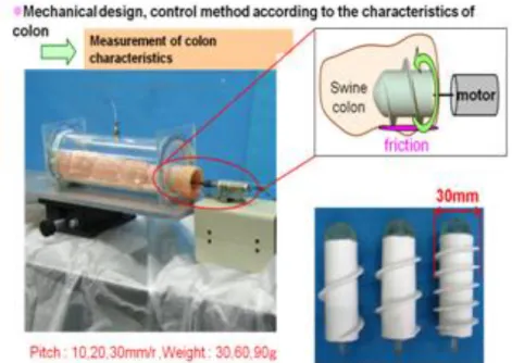
Figure 1.5 Test of characteristics of colon ; the friction property and radial elasticity of colon was measured
In figure 1.6, the device which can measure the friction force acting on the colon as a result of robot motion is shown. Dc motor is attached, which can control the input for ce and velocity to be uniform or any other specified periodic motion. The load cell that i s set on the tip of probe can measure the magnitude of force acting on the probe.
Figure 1.6 Experimental Device which can masure friction force in the colon (top) and in vivo experiment in Kyushu university hospital (bottom)
Chapter 1. Introduction
7
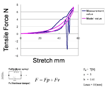
This force is recorded in the computer. Based on the experiment with live and dead swine, empirical friction force equations are used to estimate the parameters used in the bi omechanical models as shown in figure 1.7.
Model parameter is deduced from the measurement of tensile force and its stretch dat a such as figure 1.7. In this figure, model of the characteristics of colon when it receives tensile force is established using nonlinear spring element and nonlinear damping element.
This is typically lumped model which thinks of objectives as concentrated mass. This ass umption of lumpedness can be different in detail.
With this model and experimentation results, parameters controlling the model are dete rmined. The final results showing comparison between simulation and in vitro experimentat ion are shown in figure 1.8 (a), (b). In figure 1.9(a) and (b), resulting distance is shown.
Figure 1.7 Biomechanical Model of Pig colon; this model uses spring mass element to de scribe the biomechanical behavior of colon. The parameters are determined through a num ber of experimentations.
Chapter 1. Introduction
8
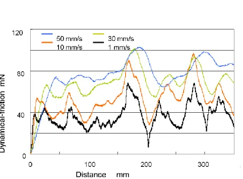
Figure 1.8 Dynamic frictions acting on the robot when rotating with different speed. This diagram shows the dynamic frictions are changing as the robot is moved in the colon wit h speed of 1, 10, 30 and 50 mm/s
The important index to movement in the colon is the distance with time. This means that as we are developing robot which can move well as a goal of research, performance on how to move well is most important.
The comparison of two results in the figure of 1.9(a) and (b) shows that this simulati on model coincides with the result of experimental results on the dead swine. Thus this al so implies that biomechanical modeling and estimation of parameters by experiments can p redict the interaction between robot and colon. Of course, simulation model cannot cover a ll real problems which can arise in the colon and robot interaction.
As it is simplified model, main issue would be the magnitude of error between two c ases. If the allowance of error is assumed which comes from experiences, accuracy of mo del would be updated
Chapter 1. Introduction
9
Mechanism of Colonoscopy robot
We had made mainly 2 types of mechanism: reverse screw type and crawling type. Rever se type adopts principle of screw in mechanics as a locomotion mechanism. Crawling type uses grasp and pull motion with hook like leg.
Reverse Screw Type
Colon is flexible, long and thin organ, inside of which is sloppy. The colon is not securel y fixed to the human body [7][16]. It is more reasonable to say that it is hanged in the human body.
J. Zuo proposed micro creeping colonoscopy robot which has locomotion mechanism of ea rthworm. This robot uses several extensor units making locomotion possible by contracting and extending its body. This robot has 7.5mm diameter and 120mm length and 12.5g of weight. They have tested it in the rubber tube [16]. In [23], multi slider linkage mechanis m for endoscopic forceps manipulator was developed. Active tubular polyarticulated micro system was too implemented for flexible endoscope [24].
Figure 1.9(a) Distance – Time relation of dead pig case
Chapter 1. Introduction
10
Crawling type
As an alternative mechanism to the rotational locomotion, crawling type of mechanism was researched in recent days. In mechanical point of view, this has benefit compared to the r otation type. First of all, complex modeling concerning on the interaction between robot a nd colon is not needed. In this mechanism, robot can grasp inner wall of colon by mecha nical legs. So it can avoid slipping which usually becomes one of cause which lowers the running performance of robot in the colon.
Figure 1.11 shows the crawling type of robot. This robot has legs on its own. Using this leg which is wire controlled by motors, robot can grasp the protruded part of colon such as mucosal ring of colon and move by pushing this part as the power point.
Figure 1.9(b) Distance – Time relation of simulation Model
Figure 1.10 Reverse screw type of robot
Chapter 1. Introduction
11
Control of Colonoscopy Robot
In order to control the robot, velocity feedback controller was developed and reinforcement algorithm was applied to meet unpredictable change of situation in the movement.
Velocity feedback Motor Controller
In the view point of control strategy, the minimum requirement which is demanded to the system is to ensure ability to meet varying situation of surroundings. With this demand i n mind, the implementation of reinforcement learning technique had been made. This meth od allows some degree of flexibility of uncertainty on the design of controller performance, which is inevitably induced when we try to evaluate the noise contaminated sensor data.
Figure 1.11 Colonoscope robot which have crawling mechanism.
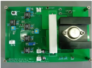
Figure 1.12 shows the appearance of analog type of velocity feedback controller. Thi s board uses analog type of power amp at the motor current supply source. This power a mp can seamlessly supply current and have broad bandwidth compared to the digital-analo g chip type of amplifier. In order to remove the heat from the amplifier, the heat sink th at is made of aluminum plate is attached beneath the amplifier. The wide area of heat si nk dissipates heat effectively.
The main circuit is made of operational amplifier. Current detection is also made usi ng shunt resistor which measures the change of current by the voltage drop. The white pa rt on the figure is the shunt resistor, which can dissipate heat which comes from current f
Chapter 1. Introduction
12
low.
Figure 1.12 Robot Controller for driving motors by using velocity feedback.
It uses operational amplifier and power amplifier to protect noise contamination. Digital control often happens to make trouble in case long distance line is needed for control. Thi s control board can prevent this kind of trouble and confirm secure and robust control. Th is concept is important specials in biomechanical system.
In figure 1.13 the system configuration for movement is shown. As shown on the figure, the robot can move in the colon by the mechanism of reverse screw type of driving syst em. Hiromasa et al [23] developed multi-slider linkage mechanism for endoscopic forceps manipulator. This mechanism was devised to give ability to bend flexibly in the colon.
Reinforcement Learning Control
As a control method, reinforcement learning was used. This method has different str ucture compared with classical control method [20][21]. It stresses on the interaction betwe en surroundings and robot. Here, if we say using terminology which is popular in this dis cipline, robot is called as agent and colon is named as surrounding or environment.
Programmer usually suggests agent (here, robot) the list of options agent can select.
Agent usually makes logical decision based on the expectation maximization of objective f unction. Total summation of expected return is usually objective to agent. Within this term inology, return is a kind of benefit or goal robot pursues. Action is the name of robot‟s l
Chapter 1. Introduction
13
ogical endeavor to improve current situation and obtain maximum expected return.
Figure 1.13 colon control: control is carried out through program which runs on the PC. I t applies reinforcement learning algorithm in order to understand situation based on the co ming signals through sensors installed on the robot and make suitable decision on the var ying situation.
Most important and distinct characteristics of this method are to use value function and action value function. Value function is defined based on the expectation of state. This is generally defined by the expected value of maximum return when agent starts from curren t state to possible state following given policy. Action value function is expected value of action state pair, when agent is in a certain state and under certain policy it selects actio n in order to move new state. This is also called as Q value. There are several methods on computing Q value;
Generally, number of state is finite. State transition from one state to another state i s assumed to follow Markov process. Thus proposition of the Markov discrete process is used.
Maximum return can be changed due to policy that agent carries out during control.
There are several modifications of algorithm to implement this strategy. Figure 1.11 show s the configuration diagram of control system and relation between agent and environment.
Chapter 1. Introduction
14
Figure 1.14 control strategy which was implemented on the robot
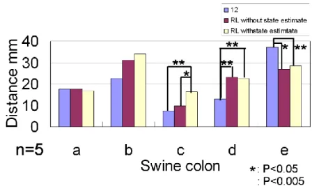
Figure 1.14 explains why reinforcement learning method is available in this kind of ti me varying situation. From the figure, we can know that RL based control is more efficie nt compared to the classical control. The main index to the performance is distance that r obot can move in the colon.
Figure 1.15 Reinforcement learning algorithm : agent( the robot in this example) predicts t he plausible state in the near future and through optimization process such as maximizing objective function ( here, total reward 𝒓(𝒕)) action is selected
Figure 1.15 explains actor-critic algorithm which is widely used.
Figure 1.16 is the result of measurement of performance on robot locomotion on the colon. Experiment was made on two cases; one is without RL and the other is wit h reinforcement learning control scheme. As can be seen in the figure 1.13, we can under stand that reinforcement learning algorithm improves system performance.
Chapter 1. Introduction
15
Figure 1.16 performance of robot: the experiment was carried out with live and dead swin e.
Sensing methods of shape of robot endoscope
Shape Estimation method using orientation sensors is carried out in this paper. From next chapter, this method is expounded in detail.
Medical Imaging
Medical imaging is the one of final option, say, detecting inflamed lesion and treatment and cure, in the medical robotics area [19]. In medical field, noncontact inspection is pop ular because it doesn‟t give damage to the human body. It has enormous spectrum in its application. There are several commercialized medical scanner such as CT, MRI, X-ray an d PET-CT. colonoscopy.
Issues relating to the colonoscopy come as the following.
1) Recognition where we are as navigation point of view of robot.
2) Detection of tumor or polyps in the colon, specially hidden tumors or polyps can be one of major issues.
Autonomous technology on where we are in the colon is essential in robotics. This agai n includes sophisticated and several sub-issues such as lumen detection or muscle wrinkles inside wall of colon or blood vessel which can be seen on the surface of colon. Lumen is the darkest area when colon is seen through camera attached on the distal tip of colono
Chapter 1. Introduction
16
scopy. It is deeply related to the center of cross section of the colon. With various region s growing methods can be applied as seen in the figure 17 (b). Recently pixel based stoc hastic process is introduced to analyze the image.
Figure 1.17 Medical Image processing: processed image (a) by hough transform line detect ion. Short lines on the boundary of wrinkles should be seperated with searching algorithm such as perceptual grouping.
(b) the lumen detection; rigion growing methods are used to detect the darkest area in the image. Histogram based detection is generally used but some degree of uncertainty exists on each method.
In the figure 1.18, the active contour algorithm is implemented to find the ring on the surface of colon. Active contour algorithm is also called as snake algorithm. It uses seeds points around the target. The objective function is made by the linear combination of sev eral type of defined energy. Here internal energy is defined by the curvature of curve whi ch comes from the extraction of edges. Image energy is also defined by the intensity of p ixels. The objective function is minimized using the differentiation of function.
Chapter 1. Introduction
17
Figure 1.18 colon boundary evaluation using active contour algorithm. This method uses o ptimization technique in which Energy that object boundary has is formulated and is recur sively evaluated toward the minimization to detect the object boundary. Iteration loop is u sed. Digit on the Left upper of the image shows its iteration number.
1.3 Motivation and Objective of the research
Motivation
Colonoscope is the medical device with which physicians investigates suspicious lesions of patient‟s lower intestinal bowel and makes operation for removing polyps or deceased lesion. After it was developed in 1950, it had been used and improved with many people since that time. At present days in the clinic, it became prerequisite medical device in detecting decease of the digestive system of human being.
Modern commercialized colonoscope has various functions as a medical device. Commercia l endoscope has two major functions; one is function for detecting deceased lesions in the digestive system. Another major one is function for making operation such as removing p olyps, suturing. For the purpose of the detection of decease, it has camera at the distal tip, light source to brighten the object. For the purpose of making operation, it has various t ype of forceps, snare. Besides, it has water and air ways for cleansing and ballooning.
Chapter 1. Introduction
18
Although its function is reliable and convenient to handle, the main demerit of endosco pe is that it requires elaborate skill to handle smoothly and it takes long time and abunda nt experiences to get skilled with endoscope. The time to take endoscopy is inversely prop ortional to the inconvenience of patients and physician himself/herself together.
Fig.1 shows in detail the time that endoscope is arrived at the appendix. In this experime nt, physicians were grouped to several levels according to their experience and skill level.
Times from inserting endoscope through anus to arrival at the appendix were measured.
In the Fig.1, GM1, GM2… means groups of skillful physician. We can know from the Fig.1 that in case of skillful physician, handling time were around 20.0minutes, meanwhil e times of other groups have various distribution from around 40.0minutes to 1hours or so.
The long training time is caused from the demand of the dexterity and complexity of ski ll to handle endoscope while investigating medical information. If the complexity of operat ion in endoscopy can be reduced to the reasonable level, the time will be also decreased.
The complexity of skill comes from the characteristic of the intestine. Upper intestine h as the form of long thin flexible and multiply bended tube. Specially, lower intestine is se verely folded. In order to make endoscope forward in the lower intestine, the stretching be havior of folded section is needed to go smoothly. With this reason, flexibility of endosco pe is prerequisite characteristics. But this flexibility of material of endoscope also becomes a cause of increases of complexity in skill in handling the endoscope. Physician carries o ut behaviors such as pushes, pulls or twists with grasping body of endoscope at the entran
Figure 1.19 Time to go from the anus to appendix.
0 200 400 600 800 1000 1200 1400
GM1 GM2 GM3 GM4 GM5 GM6 Other1 Other2 Other3 Other4 Other5 上行結腸
脾弯曲,横行結腸 下行結腸 S状結腸 直腸
Chapter 1. Introduction
19
ce such as mouse or anus. In some case, even pushing endoscope, it doesn‟t move forwar d. This phenomenon is called “looping”.
Once loop is formed, the endoscope is not moved forward inward the lower intestine, even though physician pushes it at the entrance. This complexity can be reduced when the shape of the endoscope in the colon is provided.
The shape of the endoscope is not informed to the physician in the commercial endosc ope system. At present, commercial endoscope in the market generally don‟t have such fu nction except the product of Olympus Co., ltd. But in the laboratory, systems which can provide information of the shape of endoscope to the physician in operation are developed and related researches on the technique to estimate the shape are carried out.
Objective of this Research
The purpose of this research is to develop the methodology which can visualize the vivid shape of the colonoscope that is moving in the colon by the manipulation of physician an d to provide the physician the suitable information which is processed optimally to the ph ysician.
Figure 1.20 Appearance view of the magnet ic sensing system of shape of colonoscopy in the colon. This system uses ferrous coil string. This coil string is inserted through t he pass way of colonoscopy which is used for forceps. Then transmitter and receiver w hich is shown on the figure radiates magnet ic field on the patient. The coils in the col on reflect the magnetic wave. The receiver detects the coil and computer calculates the shape of the colonoscopy.
Chapter 1. Introduction
20
1.4 Organization of the Paper
This paper consists of 6 chapters; hardware and methodology and experimental result and analysis.
In chapter 1, simplified introduction on the history of development of colonoscope is made. In chapter 2, hardware which is used in this research is explained. Accelerometer, g yroscope and magnetometer are introduced. Then noise filtering is introduced. Finally, in o rder to improve the state of inaccuracy of precision of sensor, fusion of several compleme ntary sensors is approached. Kalman and Extended Kalman filtering is introduced and com pared with the particle filtering which can be adapted even on the situation that the proce ss is not linear and non Gaussian.
In chapter 3, orientation interpolation is introduced. Orientation interpolation is different to the one of position interpolation as the orientation is not closed to the domain of mat rix multiplication.
Also the distance between interpolated points is uniformly recalculated through Arc len gth reparametrization. Numerical method is suggested as an approximate method solving pr oblem
In chapter 4, the location of the interpolated points in the Euclidian space is estimated using approximate kinematic chain model.
Chapter 5 discusses the results which were obtained from the implementation of the metho dology to the restricted experimental environment.
In the figure 1.21, the final goal of hardware is conceptually displayed.
1.5 Concluding Remarks
In this chapter, history of colonoscopy was explained. Process adding various functions to become up to the current system had been explained, which allows it to make state of the art precise inspection. Motivation on what sparked the development of this paper was prov ided and what was carried out and is going on in the laboratory was in detail introduced, specifically on the issues spanning locomotion, control and navigation.
Chapter 1. Introduction
21
Figure 1.21 Conceptual Sketch of the New Colonoscope Tube