JAIST Repository: An investigation of a state machine visualization tool SMGA & case studies with SMGA [課題研究報告書]
82
0
0
全文
(2) Master’s Research Project Report. An investigation of a state machine visualization tool SMGA & case studies with SMGA. Midori Kobayashi. Supervisor Kazuhiro Ogata. Graduate School of Advanced Science and Technology Japan Advanced Institute of Science and Technology (Information Science). March, 2021.
(3) Abstract Nowadays, the Internet and other software systems are used everywhere. For example, e-commerce systems such as Amazon and Rakuten have permeated our lives and are an integral part of our daily lives. If these systems do not work as intended, they may cause economic loss or human damages, which will not make our lives more convenient, but rather cause serious consequence. And the most core softwares of the Internet is a distributed system. It is not easy to develop a distributed system as desire because the systems are often concurrent programs. For example, in concurrent program, many processes and computers must use shared resources such as memory to meet certain constraints, so it is known that it is very difficult to develop a distributed system to work as intended and does not behave in any other way. To develop a distributed system (worked as intended), many technologies need to be used strictly. One such technique is formal verification. Formal verification can be categorized into model checking and theorem proving. Model checking often is used to detect defects, and theorem proving is necessary to ensure that the system works as intended. However, theorem proving often needs lemmas, which require much human effort. Finding lemmas is a big barrier of theorem proving in formal verification. On the other hand, humans are good at visual perception. State Machine Graphical Animation (SMGA) can be known as a tool that supports the use of theorem proving and information visualization. The tool has potential to remove or subordinate the barriers to lemma discovery. The purpose of this study mainly is to survey case studies of SMGA. Maude is used to generate the state sequence of the state machine, which is the input of SMGA. For this reason, this research includes a survey on state machines, how to formalize protocols as state machines, how to describe state machines in Maude (how to create formal specifications), how to model check (the specifications) in Maude that state machines satisfy desired properties, and how to generate state sequences of state machines using Maude. In this research report, five protocols will be studied. These include the Test & Set protocol (TAS), a flawed version of the Test & Set protocol (FTAS), the Qlock protocol, two flawed versions of the Qlock protocol (FQlock0 and FQlock1), and the Anderson protocol. Specifically, we will learn what kind of pseudocode these protocols are written in and what kind of rewriting rules are used. Then, we will explain how to visualize these protocols in SMGA and how to design them. Various figures will be used for the design. In this way, we will not only visualize the design, but also make it easy to.
(4) discover the characteristics. Then, we will describe what characteristics we found for each protocol by using SMGA. Finally, the correctness of these characteristics will be discovered by model checking. To create a graphical animation using SMGA, an input file is required. To create the input file, we need to generate the state sequence using Maude. Also, Maude is used for model checking. In Maude, we use the search command, one of the important commands, which can search for a user-specified state and confirm whether the state exists. Moreover, we will describe how to create a good diagram for graphical animation, how to observe graphical animations and look for protocol characteristics. These contents should be described concerning what characteristics you found in the animations you created in SMGA. We will then use these to help us discover even better ways to create diagrams and find characteristics of protocols. One of the future tasks of the project report is to provide an important theorem proving in formal verification. We can perform model checking and formal verification to develop distributed systems as intended. Learning both of two techniques will be of great help in developing software that supports our daily lives. In addition to learning theorem proving, it is also important to learn how the applied protocols in the report are used in the software that we use in our daily lives. It will help us to further understand the report and learn about software development. In addition to the search command, there are many other commands in Maude. By using such that commands, we can perform various types of model checking. Model checking is excellent for finding defects in software development. In other words, using various commands is useful for finding various kinds of defects.. 2.
(5) Contents 1 Introduction 1.1 Overview . . . . . . . . . . . . . . . . . . . . . . . . . . . . . . 1.2 Aims and Significance . . . . . . . . . . . . . . . . . . . . . . 1.3 Report Outline . . . . . . . . . . . . . . . . . . . . . . . . . .. 1 1 1 2. 2 Preliminaries 2.1 Mutual Exclusion . . . . . . . . . . . 2.2 State Machine . . . . . . . . . . . . . 2.3 Maude . . . . . . . . . . . . . . . . . 2.4 State Machine Graphical Animation .. . . . .. 3 3 4 4 5. . . . . . . . . . .. 8 8 8 10 12 13 17 18 19 20 21. . . . . . . .. 26 26 27 28 29 31 34 35. . . . .. . . . .. . . . .. . . . .. . . . .. . . . .. . . . .. . . . .. . . . .. . . . .. . . . .. . . . .. . . . .. 3 Variants of Test & Set (TAS) Mutual Exclusion Protocol 3.1 FTAS: A flawed version of TAS . . . . . . . . . . . . . . . . 3.1.1 Description of FTAS in Maude . . . . . . . . . . . . 3.1.2 State Machine Representation(FTAS) . . . . . . . . . 3.1.3 Use of SMGA(FTAS) . . . . . . . . . . . . . . . . . . 3.1.4 Model Checking Using Maude(FTAS) . . . . . . . . . 3.2 TAS: A protocol satisfies mutual exclusion . . . . . . . . . . 3.2.1 Description of TAS in Maude . . . . . . . . . . . . . 3.2.2 State Machine Representation(TAS) . . . . . . . . . 3.2.3 Use of SMGA(TAS) . . . . . . . . . . . . . . . . . . 3.2.4 Model Checking Using Maude(TAS) . . . . . . . . . 4 Variants of Qlock Mutual Exclusion Protocol 4.1 FQlock0: A flawed version of Qlock protocol . . 4.1.1 Description of FQlock0 in Maude . . . . 4.1.2 State Machine Representation(FQlock0) 4.1.3 Use of SMGA(FQlock0) . . . . . . . . . 4.1.4 Model Checking Using Maude(FQlock0) 4.2 FQlock1: A protocol satisfies mutual exclusion . 4.2.1 Description of FQlock1 in Maude . . . . 1. . . . . . . .. . . . . . . .. . . . . . . .. . . . . . . .. . . . . . . .. . . . . . . .. . . . . . . ..
(6) 4.3. 4.2.2 4.2.3 4.2.4 Qlock: 4.3.1 4.3.2 4.3.3 4.3.4. State Machine Representation(FQlock1) Use of SMGA(FQlock1) . . . . . . . . . Model Checking Using Maude(FQlock1) A protocol satisfies mutual exclusion . . Description of Qlock in Maude . . . . . . State Machine Representation(Qlock) . . Use of SMGA(Qlock) . . . . . . . . . . . Model Checking Using Maude(Qlock) . .. 5 Anderson Mutual Exclusion Protocol 5.1 Description of Anderson in Maude . . . . 5.2 State Machine Representation(Anderson) 5.3 Use of SMGA(Anderson) . . . . . . . . . 5.4 Model Checking Using Maude(Anderson). . . . .. . . . .. . . . .. . . . .. . . . . . . . .. . . . . . . . .. . . . . . . . .. . . . . . . . .. . . . . . . . .. . . . . . . . .. . . . . . . . .. . . . . . . . .. 37 39 40 42 43 44 45 46. . . . .. . . . .. . . . .. . . . .. . . . .. . . . .. . . . .. . . . .. 56 57 59 61 62. 6 Lessons Learned 66 6.1 How to create a good diagram for graphical animation . . . . 66 6.2 How to Observe Graphical Animations and Look for Protocol characteristics . . . . . . . . . . . . . . . . . . . . . . . . . . . 68 7 Conclusion 70 7.1 Summary of the research report . . . . . . . . . . . . . . . . . 70 7.2 Future Issues . . . . . . . . . . . . . . . . . . . . . . . . . . . 71.
(7) List of Figures 2.1 2.2 2.3 2.4. An example of mutual exclusion . . A series of graphical animations. . . Example of an input file . . . . . . Example of an input file to SMGA. . . . .. . . . .. 3 6 7 7. 3.1 3.2 3.3 3.4 3.5 3.6 3.7 3.8 3.9 3.10 3.11. Representing the rewriting rules using a figure . . . . . . . . Representing the state machine using a figure . . . . . . . . Visually representing the state machine using SMGA . . . . A representation of the process using a figure . . . . . . . . A representation of the section using a figure . . . . . . . . . A representation of the value of “lock” using the figure . . . Input files used in FTAS . . . . . . . . . . . . . . . . . . . . Diagram showing the initial conditions using SMGA(FTAS) Visual representation of various state machines using SMGA The state does not meet the mutual exclusion of the machine Figure showing that there can be up to three processes in each section at the same time. . . . . . . . . . . . . . . . . . . . . Figure showing that the value of “lock” will be false if all processes are present in rs . . . . . . . . . . . . . . . . . . . Figure showing that if there is no process in cs, the value of “lock” will be false . . . . . . . . . . . . . . . . . . . . . . . Representing the rewriting rules using a figure(TAS) . . . . . Representing the state machine using a figure . . . . . . . . Visually representing the state machine using SMGA . . . . A representation of the process using a figure . . . . . . . . A representation of the section using a figure . . . . . . . . . A representation of the value of “lock” using the figure . . . Input files used in TAS . . . . . . . . . . . . . . . . . . . . . Diagram showing the initial conditions using SMGA(TAS) . Visual representation of various state machines using SMGA(TAS) . . . . . . . . . . . . . . . . . . . . . . . . . . Figure showing that there is at most one process in cs. . . .. . . . . . . . . . .. 10 10 11 11 11 12 12 13 14 15. 3.12 3.13 3.14 3.15 3.16 3.17 3.18 3.19 3.20 3.21 3.22 3.23. 3. . . . .. . . . .. . . . .. . . . .. . . . .. . . . .. . . . .. . . . .. . . . .. . . . .. . . . .. . . . .. . . . .. . 15 . 16 . . . . . . . . .. 16 19 20 20 21 21 22 22 23. . 24 . 25.
(8) 4.1 4.2 4.3 4.4 4.5 4.6 4.7 4.8 4.9 4.10 4.11 4.12 4.13 4.14 4.15 4.16 4.17 4.18 4.19 4.20 4.21 4.22 4.23 4.24 4.25 4.26 4.27 4.28 4.29 4.30 4.31 4.32 4.33 4.34 4.35. Representing the rewriting rules using a figure(FQlock0) . . . Representation of a state machine in a diagram(FQlock0) . . . Visually representing the state machine using SMGA(FQlock0) A representation of the process using a figure(FQlock0) . . . . A representation of the section using a figure(FQlock0) . . . . A representation of the queue using a figure(FQlock0) . . . . . Representation of tmp[p1] and tmp[p2] using figures(FQlock0) Input files used in FQlock0 . . . . . . . . . . . . . . . . . . . . Diagram showing the initial conditions using SMGA(FQlock0) Visual representation of various state machines using SMGA(FQlock0) . . . . . . . . . . . . . . . . . . . . . . . . . There are at most two processes in each section at the same time. . . . . . . . . . . . . . . . . . . . . . . . . . . . . . . . . Mutual exclusion is not satisfied because two processes can exist simultaneously in cs. . . . . . . . . . . . . . . . . . . . . Representing the rewriting rules using a figure(FQlock1) . . . Representation of a state machine in a diagram(FQlock1) . . . Representation of a state machine in a diagram(FQlock1) . . . A representation of the process using a figure(FQlock1) . . . . A representation of the section using a figure(FQlock1) . . . . A representation of the queue using a figure(FQlock1) . . . . . Representation of tmp[p1] and tmp[p2] using figures(FQlock1) Input files used in FQlock1 . . . . . . . . . . . . . . . . . . . . Diagram showing the initial conditions using SMGA(FQlock1) Visual representation of various state machines using SMGA(FQlock1) . . . . . . . . . . . . . . . . . . . . . . . . . It indicates that there is at most one process in cs. . . . . . . It indicates that there is at most one process in ds. . . . . . . It shows that two processes can exist simultaneously in rs and ws. . . . . . . . . . . . . . . . . . . . . . . . . . . . . . . . . . Representing the rewriting rules using a figure Qlock . . . . . Representation of a state machine in a diagram(Qlock) . . . . Visually representing the state machine using SMGA(Qlock) . A representation of the process using a figure(Qlock) . . . . . A representation of the section using a figure(Qlock) . . . . . A representation of the queue using a figure(Qlock) . . . . . . Input files used in Qlock . . . . . . . . . . . . . . . . . . . . . Diagram showing the initial conditions using SMGA(Qlock) . Visual representation of various state machines using SMGA (Qlock) . . . . . . . . . . . . . . . . . . . . . . . . . . . . . . Indicates that there can be at most one process in cs. . . . . . 4. 29 30 30 31 31 32 32 33 34 35 36 37 38 38 39 39 40 40 41 42 43 48 49 49 50 50 50 51 51 51 51 52 52 53 54.
(9) 4.36 It shows that two processes can exist simultaneously in rs and ws. . . . . . . . . . . . . . . . . . . . . . . . . . . . . . . . . . 54 4.37 When a process exists in rs, it means that the value of the process does not exist in queue. . . . . . . . . . . . . . . . . . 55 5.1 5.2 5.3 5.4 5.5 5.6 5.7 5.8 5.9. 5.11 5.12 5.13. Representing rewrite rules using diagrams . . . . . . . . . . . Representing state machines using diagrams . . . . . . . . . . Using SMGA to visually represent state machines . . . . . . . Use figures to represent processes. . . . . . . . . . . . . . . . . Use figures to represent sections. . . . . . . . . . . . . . . . . . Representation of place[p1],place[p2],place[p3] using figures . . Represent (place[p1]: 1) and (place[p1]: 2) using a figure. . . . Represent (next: 0), (next: 1), and (next: 2) using a diagram . Using a figure to represent (array[0]: true) (array[1]: false) (array[2]: false) . . . . . . . . . . . . . . . . . . . . . . . . . . Use the figure to represent (array[0]: false) (array[1]: true) (array[2]: false) and (array[0]: false) (array[1]: false) (array[2]: true) . . . . . . . . . . . . . . . . . . . . . . . . . . . . . . . . Input files used in Anderson . . . . . . . . . . . . . . . . . . . Diagram showing the initial conditions using SMGA(Anderson) Visual representation of various states using SMGA . . . . . .. 6.1. Graphical animation without graphics. . . . . . . . . . . . . . 67. 5.10. 58 59 59 60 60 60 61 61 61. 62 62 63 65.
(10) Chapter 1 Introduction 1.1. Overview. Most mission-critical software, such as the Internet, is a distributed system. It is difficult to develop distributed systems as intended, and many technologies must be used securely. Formal verification is one such techniques. Formal verification can be classified into model checking and theorem proving. Model checking is good at detecting defects, while theorem proving is necessary to ensure that the system works as desire. However, theorem proving often uses lemmas, which require much human effort in most cases. On the other hand, humans have a high visual perceptual ability [1, 2, 3, 4]. To take advantage of this fact, a support tool for visualizing the behavior of state machines, which are mathematical models of distributed systems, has been developed, State Machine Graphical Animation (SMGA). SMGA can be known as a tool to facilitate the use of theorem proving and information visualization.. 1.2. Aims and Significance. The purpose of this study is mainly to investigate a case study of SMGA, where Maude is used to generating a state sequence of state machines, which are inputs to SMGA. Therefore, this investigation includes investigation of state machines, how to formalize protocols as state machines, how to describe state machines in Maude (how to create formal specifications), how to model check in Maude that state machines satisfy desired properties, and how to generate state sequences of state machines using Maude. Today, the Internet and other software systems are used everywhere. For example, e-commerce systems such as Amazon and Rakuten are pervasive in 1.
(11) our lives and are an integral part of our daily lives. If these systems do not work as intended, they may cause economic loss and human damages, which may cause serious consequences instead of making our lives more convenient. Most of the core software systems take the form of distributed systems. It is known that it is very difficult to develop distributed systems in such a way that they work as intended but do not work in any other way because many processes and computers must use shared resources such as memory to satisfy certain constraints. Formal verification based on theorem proving is one of the most powerful techniques to verify distributed systems work as intended. However, it is necessary for humans to discover lemmas. SMGA has the potential to remove or subordinate the barriers for theorem proving in formal verification. In this sense, this study is important.. 1.3. Report Outline. The following is a report on the research project. ・Chapter 1: Introduction In this chapter, we introduced the overview, aims, and significance of the thesis. ・Chapter 2: Preliminaries In this chapter, we will explain the terms used in the research project: Mutual exclusion, State machine, Maude, and State Machine Graphical Animation. ・Chapter 3: Variants of Test&Set (TAS) Mutual Exclusion Protocol This chapter introduces the Test&Set (TAS) Protocol. ・Chapter 4: Variants of Qlock Mutual Exclusion Protocol In this chapter, we introduce the Qlock Protocol. ・Chapter 5: Variants of Qlock Mutual Exclusion Protocol In this chapter, we will introduce the Anderson Mutual Exclusion Protocol. ・Chapter 6: Lessons Learned In this chapter, I will describe what I learned from the research report. ・Chapter 7: Conclusion In this chapter, the summary of the research report and future tasks will be discussed.. 2.
(12) Chapter 2 Preliminaries 2.1. Mutual Exclusion. Mutual exclusion refers to the process of maintaining consistency when many processes can use a shared resource in the execution of a computer program. When conflicts occur due to simultaneous accesses from multiple processes, mutual exclusion is a process to maintain consistency by preventing other processes from using the resource while allowing one process to use it exclusively. In other words, it is to prevent multiple processes (or threads) from entering a critical section at the same time. A critical section is a period of time when a process is accessing a shared resource such as shared memory. For example, when some people share a bicycle[5], the queue is used to consider whether the bicycle should be given to at most one person. Let’s assume that the initials are put in a queue in the order of Emma, David, and Alice. Emma is allowed to use the bike first, and she will be removed (dequeued) from the queue when she used the bike. Then the next person who is allowed to use the bike will be David. Figure 2.1 shows an example of the mutual exclusion protocol when a bicycle is shared.. Figure 2.1: An example of mutual exclusion. 3.
(13) 2.2. State Machine. A state machine is a mathematically abstract “model of behavior” consisting of a finite number of states, transitions, and behaviors. It is sometimes used in program design to study how logic flows when a series of states are taken. It takes one state out of a finite number of “states”. At a certain point in time, only one state is taken, and it is called the “current state” of that point in time. Some event or condition causes a transition from one state to another, which is called a transition. A transition is defined by enumerating the states that can be transitioned from each current state and the conditions that trigger the transition.. 2.3. Maude. Maude [4] is an algebraic specification language developed by a team led by Jose Meseguer. Maude is a rewriting logic-based specification and programming language. The states of a state machine are represented by data such as OComp and associative commutative sets (called Soup), and state transitions are described by rewrite rules. The rewrite rule takes the form rl[l]: t → t ′. where t, t ′is homogeneous terms containing variables, and l is the label of the rule. For the rewrite rule, if a state satisfies the conditions of t, it can be changed to the state of t ′. Maude also provides several built-in modules, such as BOOL and NAT for Boolean values and natural numbers. Boolean values are represented as true or false, and natural numbers are represented as usual as 0, 1, 2, ... as usual. By using an example, we will explain the rewriting rules. rl [enter] : {(pc[I]: rs) (lock: false) OCs} =>{(pc[I]: cs) (lock: true) OCs} . rl denotes a rewrite law, and [enter] is the label of the rewrite law. If a state satisfies {(pc[I]: rs) (lock: false) OCs}, then it can be rewritten to the state {(pc[I]: cs) (lock: true) OCs} . Here, there are processes p and q, I represents the ID of the process, and p and q are defined by I. There are two sections, rs (Remainder Section) and cs (Critical Section), which represent the locations where the processes exist. In other words, (pc[I]: rs) means that a process is located in rs. the lock is a Boolean value and can take the values true or false. (lock: false) means that the value of the lock is false. “OCs” is called an observer component. Observer component means that when processes p and q exist, in {(pc[p]: rs) (lock: false) OCs}, (pc[p]: rs) specifies the value of process p. Also, (lock: false) specifies the value of lock. However, the value of process q is not specified. In this case, process q becomes an observer component. In other words, 4.
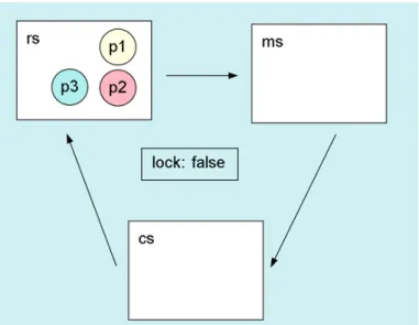
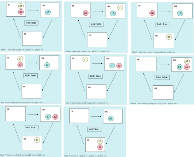
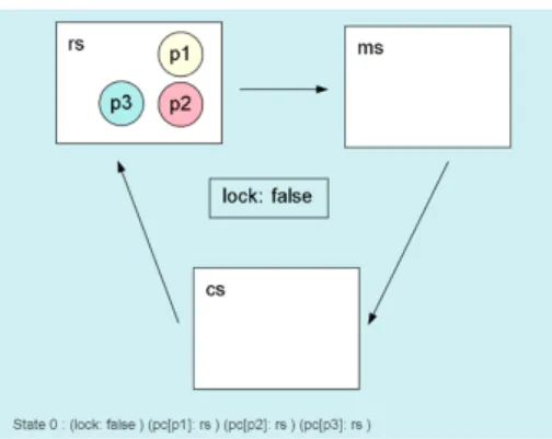
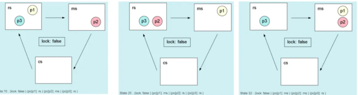
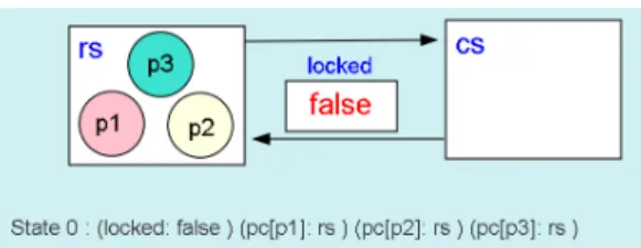
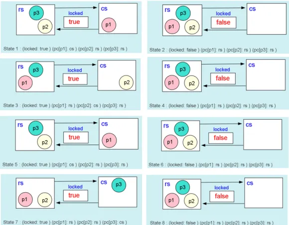
(14) an observer component is a value that is not specified among the values that exist. There are various functions in Maude, and this paper deals with the search command. The search command can search for a user-specified state in an input file. We will use an example to explain the search command. Maude> search [1] in TAS : init =>* {(pc[p1]: cs) (pc[p2]: cs) OCs} .. The phrase “search [1] in TAS” means to search for one specified state in the user-created module “TAS”. “init” indicates the initial state. The userspecified state is the state described to the right of “=>”. In other words, “init =>* {(pc[p1]: cs) (pc[p2]: cs) Ocs}.” searches for the state “{(pc[p1]: cs) (pc[p2]: cs) Ocs}.” from the initial state. There are two patterns of output results for the search command. The first is No solution. This means that the user-specified state was not found. The second is Solution 1, which means that the user-specified state exists.. 2.4. State Machine Graphical Animation. State Machine Graphical Animation(SMGA) [3] is implemented using the drawing web app DrawSVG (www.drawsvg.org). It designs an image for each state and observes the characteristics of the state by considering the sequence of images, obtained by simple computation, as a movie. The sequence of images is represented in Figure 2.1. if the image input to SMGA has three processes, we can design an image for each state as shown in Figure 2.2. As shown in Figure 2.2, the input file to SMGA consists of three parts: ###keys, ###textDisplay, and ###states. Figure 2.3 shows an example of an input file to SMGA. In this ###keys part, the names (or keys) used by the observable components that make up the state are listed. In the case of Figure 2.4, locked, pc[p1], pc[p2], and pc[p3] are enumerated. using SMGA, the values displayed in the keys to represent the state are represented by various figures. Figure 2.4, we use circles to represent processes, and rectangles to represent rs (Remainder Section), cs (Critical Section), and locked. Figure 2.2 shows a series of states generated by SMGA. For example, in state 2, processes p1, p2, and p3 exist in rs and the value of locked is false; in state 3, the next state after state 2, p2 that existed in rs disappears and exists in cs and the value of locked changes to true. From this series of changes, we can observe that process p2 has moved from rs to cs and the value of locked has changed from false to true. In other words, the state of Figure 2.2 can be inferred that when a process moves from rs to cs, the value of locked changes from false to true. In this way, SMGA can help us 5.
(15) understand the characteristics of a state from a series of images, and using Maude, we can also verify that the characteristics obtained from SMGA are correct. Maude> search [1] in TAS : {(pc[p1]: rs) (pc[p2]: rs) (pc[p3]: rs) (lock: false) } =>* {(pc[p1]: rs) (pc[p2]: cs) (pc[p3]: rs) (lock: true) } . Solution 1 (state 2). The search command shows a test to see if it is possible to change from state 2 to state 3. The output result is Solution1, which indicates the existence of the predicted result. In this way, we can check whether the characteristics predicted by SMGA are correct by using Maude.. Figure 2.2: A series of graphical animations.. 6.
(16) Figure 2.3: Example of an input file. Figure 2.4: Example of an input file to SMGA. 7.
(17) Chapter 3 Variants of Test & Set (TAS) Mutual Exclusion Protocol 3.1. FTAS: A flawed version of TAS. In this chapter, we describe FTAS, a pattern that does not satisfy the mutual exclusion of Test & Set (TAS). Here, “locked” is a Boolean variable that can take the value “true” or “false”. There are many processes, which are arranged under one of three labels: rs(Remainder Section), ms(Middle Section), and cs(Critical Section). By default, each process is placed in the rs(Remainder Section) and the value of “locked” is “true”. The pseudo code of FTAS is as follows. Loop “Remainder Section” rs : while locked = true {} “Middle Section” ms : locked := true; “Critical Section” cs : locked := false;. 3.1.1. Description of FTAS in Maude. In this chapter, we will use Maude to represent the FTAS protocol. For this purpose, we describe the code used in Maude, which is assumed to have three processes called p1, p2, and p3. Therefore, we can represent the state as (pc[p1]: l1) (pc[p2]: l2) (pc[p3]: l3) (lock: B). ・“pc[ ]” represents a process counter, and the value is rs, ms, cs.. 8.
(18) ・“l1”, “l2”, “l3” takes one of the values of rs, ms, cs. ・“p1”, “p2”, and “p3” represent the ID of the process. ・“lock” represents a locked variable in the protocol. ・“B” is a Boolean variable and takes the value “true” or “false”.. In the initial state, l1, l2, and l3 are rs and B is “true”. The state transitions of FTAS are specified in Maude as the following three rewrite rules. rl [enter]: {(pc[P]: rs) (lock: false) OCs} =>{(pc[P]: ms) (lock: false) OCs} . rl [wait]: {(pc[P]: ms) (lock: B) OCs} =>{(pc[P]: cs) (lock: true) OCs} . rl [exit]: {(pc[P]: cs) (lock: B) OCs} =>{(pc[P]: rs) (lock: false) OCs} . “=>” indicates that the state changes to the arrow direction. “P” represents the process ID variable in Maude, “B” represents the Boolean variable, and takes a value of “true” or “false”. “Ocs” stands for observable components. The rewrite rule “rl[enter]” is used as an example below. It means that “{(pc[P]: rs) (lock: false) OCs}” has been changed to “{(pc[P]: ms) (lock: false) OCs}” by the rewrite rule “rl[enter]”. There are three rewrite rules: enter, wait, and exit. The three rewrite rules are explained below: Rule 1 (enter): Process P is located at rs and the lock value is false. Later, process P is located in ms and the lock value is true. Rule 2 (wait): Process P is located in ms and the lock value is B. After that, process P is located in cs and the lock value is true. Rule 3 (exit): Process P is located in cs and lock value is B. Later, process P is located in rs and the lock value is false. Figure 3.1 shows three state transition diagrams. Each time you transition from one state to another, you can indicate the process ID. Figure 3.1, explaining the rewriting rule “[enter]” as an example, if the state is “(pc[P]: rs) (lock: false) OCs”, the rewriting rule indicates that “(pc[P]: ms) (lock: true) OCs” by “[enter]”.. 9.
(19) Figure 3.1: Representing the rewriting rules using a figure. 3.1.2. State Machine Representation(FTAS). In this chapter, we will explain how to represent state machines using diagrams. Representing a state machine using a diagram helps to discover characteristics from visual information. There are three processes called p1, p2, p3, and each state is like (pc [p1]: rs) (pc [p2]: rs) (pc [p3]: rs) (lock: false). In that case, it is expressed as shown in the Figure 3.2. Figure 3.2 is a visualization of the initial state. When SMGA is used for the state of (pc [p1]: rs) (pc [p2]: rs) (pc [p3]: rs). Figure 3.2: Representing the state machine using a figure (lock: false), it is expressed as shown in the Figure 3.3. Figure 3.3 shows a visualization of the initial state using SMGA. A brief explanation will be given for the diagram using SMGA. Figure 3.4 shows the processes p1, p2, and p3 using circles. These processes are arranged in one of three sections: rs (Remainder Section), ms (Midle 10.
(20) Figure 3.3: Visually representing the state machine using SMGA Section), and cs (Critical Section). In Figure 3.5, sections rs (Remainder Section), ms (Midle Section), and. Figure 3.4: A representation of the process using a figure cs (Critical Section) are represented using squares. There are cases where processes are located within this section and cases where neither process is located. In Figure 3.6, a square is used for locked. lock will be “false” or “true” as. Figure 3.5: A representation of the section using a figure shown.. 11.
(21) Figure 3.6: A representation of the value of “lock” using the figure. 3.1.3. Use of SMGA(FTAS). This chapter describes how to use of SMGA and visually discovering characteristics. In the use of SMGA, two inputs are required: an image design and an input file. The image design is created by the user and allows the user to develop an understanding based on his or her own design. The input file is generated by Maude. The input file is generated by Maude and plays the animation to SMGA.. Figure 3.7: Input files used in FTAS Create various state machines using Maude. Figure 3.7 shows the state generated for (pc[p1]: l1) (pc[p2]: l2) (pc[p3]: l3) (lock: B). When SMGA is used for Figure 3.7, it becomes as shown in Figure 3.8 and Figure 3.9 below. Figure 3.8 shows the initial state in the input file generated using Maude. By using SMGA, it is possible to organize where each process is located and what the value stored in lock is. In state 8, there are two processes in cs. 12.
(22) Figure 3.8: Diagram showing the initial conditions using SMGA(FTAS) Figure 3.9 shows some states. In state 8, p1 and p2 are present in cs at the same time.In Figure 3.10, state 8 is represented in Figure 3.10. For this reason, the FTAS protocol described in this chapter does not satisfy mutual exclusion. By using SMGA, the following three characteristics can be guessed about FTAS. (1) There are at most three processes in each section at the same time. (2) If there are all processes in rs, the value of “lock” will be false. (3) If there are no processes in cs, the value of “lock” will be false. These three characteristics are shown in Figure 3.11 to Figure 3.13 using SMGA.. 3.1.4. Model Checking Using Maude(FTAS). In this chapter, we describe model checking with Maude, which allows us to investigate all user-specified changes in the state of a machine from one state to another. An example will be used to illustrate this. Maude> search [1] in TAS-FAILURE : init =>* {(lock: true) (pc[I:Pid]: cs) (pc[j:Pid]: cs) OCs} .. 13.
(23) Figure 3.9: Visual representation of various state machines using SMGA Solution 1 (state 20) states: 21 rewrites: 29 OCs --> pc[p3]: rs. The above command searches for the state “(lock: true) (pc[I:Pid]: cs) (pc[j:Pid]: cs) OCs .” from the conditions “init” in module “TAS-FAILURE”. “Solution 1 (state 20)” indicates that the state “(lock: true) (pc[I:Pid]: cs) (pc[j:Pid]: cs) OCs .” exists in module TAS-FAILURE at state 20. “OCs =>pc[p3]: rs” means observable components (OCs) is pc[p3] in this case. As explained above, Maude can search for a user-specified state, and we can see that the FTAS process does not satisfy mutual exclusion because more than one process exists simultaneously in cs. From the above results, we can confirm that there exists a case which con14.
(24) Figure 3.10: The state does not meet the mutual exclusion of the machine. Figure 3.11: Figure showing that there can be up to three processes in each section at the same time. tains two processes in cs.. Maude> search [1] in TAS-FAILURE : init =>* {(pc[i:Pid]: rs) (pc[j:Pid]: rs) (pc[k:Pid]: rs) (pc[l:Pid]: rs) OCs} . No solution.. The above command searches for the state “(pc[i:Pid]: rs) (pc[j:Pid]: rs) (pc[k:Pid]: rs) (pc[l:Pid]: rs) OCs .” from the conditions “init” in module “TAS-FAILURE”. “No solution” indicates that the state “(pc[i:Pid]: rs) (pc[j:Pid]: rs) (pc[k:Pid]: rs) (pc[l:Pid]: rs) OCs” does not exist in module “TAS-FAILURE ”. This indicates that no more than one new process has been added to the FTAS dealt with in this chapter, whereas only three processes are in use. From the above result, we can see that the number of processes does not increase. Also, for Figure 3.8, the value of “lock” will be false if there are all processes 15.
(25) Figure 3.12: Figure showing that the value of “lock” will be false if all processes are present in rs. Figure 3.13: Figure showing that if there is no process in cs, the value of “lock” will be false in rs.” Maude> search [1] in TAS-FAILURE : init => * {(pc[p1]: rs) (pc[p2]: rs) (pc[p3]: rs) (lock: true)} . No solution.. The above command searches for the state “(pc[p1]: rs) (pc[p2]: rs) (pc[p3]: rs) (lock: true) .” from the conditions “init” in module “TAS-FAILURE ”. “No solution” indicates that the state “(pc[p1]: rs) (pc[p2]: rs) (pc[p3]: rs) (lock: true) .” does not exist in module “TAS-FAILURE”. This indicates that the value of lock is false when all three processes, p1, p2, and p3, are in rs. If there is no process in cs, the value of “lock” is false. Model checking will output the following results. Maude> search [1] in TAS-FAILURE : init => {(pc[I:Pid]: X:Label) (pc[J:Pid]: Y:Label) (pc[K:Pid]: T:Label) 16.
(26) (lock: true) } such that X:Label =/= cs and Y :Label =/= cs and T:Label =/= cs No solution. The above command searches for the state “{(pc[I:Pid]: X:Label) (pc[J:Pid]: Y:Label) (pc[K:Pid]: T:Label) (lock: true)} such that X:Label =/= cs and Y :Label =/= cs and T:Label =/= cs” from the conditions “init” in module “TAS-FAILURE”. Also, I, J, and K take the value of one of the processes p1, p2, or p3. X, Y, and T can take values of rs, ms, and cs. However, “X:Label =/= cs”, “Y:Label =/= cs”, and “T:Label =/= cs” indicate that X, Y, and T do not take the value of cs. “No solution” indicates that the state “{(pc[I:Pid]: X:Label) (pc[J:Pid]: Y:Label) (pc[K:Pid]: T:Label) (lock: true)} such that X:Label =/= cs and Y:Label =/= cs and T:Label =/= cs” does not exist in module “TASFAILURE”. This means that, If there are no processes in cs, the value of “lock” will be false.. 3.2. TAS: A protocol satisfies mutual exclusion. In this chapter, we describe the Test & Set (TAS) that satisfies mutual exclusion. Here, “locked” is a Boolean variable that can take the value “true” or “false”. There are many processes, which are arranged under one of two labels: rs(Remainder Section) and cs(Critical Section). Initially, each process is located in the rs(Remainder Section) and the value of “locked” is “true”. The pseudo code of TAS is as follows. Loop “Remainder Section” rs : repeat while test & set(locked); “Critical Section” cs : locked := false; test & set(locked){ if locked = false 17.
(27) locked := true return false; else return true;}. 3.2.1. Description of TAS in Maude. In this chapter, we will use Maude to represent the TAS protocol. For this reason, we will describe the code used in Maude, assuming that there are three processes called p1, p2, and p3 in Maude. Therefore, we can represent the state as (pc[p1]: l1) (pc[p2]: l2) (pc[p3]: l3) (lock: B). ・“pc[ ]” represents a process counter, and the value is rs, cs. ・l1,l2,l3 takes one of the values of rs, cs. ・“p1”, “p2”, and “p3” represent the ID of the process. ・“lock” represents a locked variable in the protocol. ・“B” is a Boolean variable and takes the value “true” or “false”.. In the initial state, l1, l2, l3 are rs and B will be false. The state transitions of TAS are specified in Maude as the following two rewrite rules. rl [enter] : (pc[I]: rs) (lock: false) OCs =>(pc[I]: cs) (lock: true) OCs . rl [exit] : (pc[I]: cs) (lock: B) OCs =>(pc[I]: rs) (lock: false) OCs . “=>” indicates that the state changes to the arrow direction. “I” represents the process ID variable in Maude, “B” represents the Boolean variable, and takes a value of “true” or “false”. “Ocs” stands for observable components. “rl[enter]” is used as an example below. It means that “(pc[P]: rs) (lock: false) OCs” has been changed to “(pc[P]: ms) (lock: false) OCs” by the rewrite rule “rl[enter]”. There are two rewrite rules: enter and exit. Two rewriting rules are represented in Figure 3.14. The two rewrite rules are explained below: Rule 1 (enter): Process P is located at rs and the lock value is false. Later, process P is located in cs and the lock value is true. Rule 2 (exit): Process P is located in cs and the lock value is B. After that, process P is located in rs and the lock value is false. Figure 3.12, explaining the rewriting rule “[enter]” as an example, if the state 18.
(28) is “(pc[P]: rs) (lock: false) OCs”, the rewriting rule indicates that “(pc[P]: cs) (lock: false) OCs” by “[enter]”.. Figure 3.14: Representing the rewriting rules using a figure(TAS). 3.2.2. State Machine Representation(TAS). In this chapter, we will explain how to represent state machines using diagrams. Representing a state machine using a diagram helps to discover complements from visual information. There are three processes called p1, p2, p3, and each state is like (pc[p1]: rs) (pc[p2]: rs) (pc[p3]: rs) (lock: false). In that case, it is expressed as shown in the Figure 3.15. Figure 3.15 is a visualization of the initial state. When SMGA is used for the state of (pc[p1]: rs) (pc[p2]: rs) (pc [p3]: rs) (lock: false), it is expressed as shown in the Figure 3.16 below.. A brief explanation will be given for the diagram using SMGA. Figure 3.17 shows the processes p1, p2, and p3 using circles. These processes are arranged in one of three sections: rs (Remainder Section) and cs (Critical Section). In Figure 3.18, sections rs (Remainder Section) and cs (Critical Section) are represented using squares. There are cases where processes are located within this section and cases where neither process is located. 19.
(29) Figure 3.15: Representing the state machine using a figure. Figure 3.16: Visually representing the state machine using SMGA. In Figure 3.19, a square is used for locked variable. lock will be “false” or “true” as shown.. 3.2.3. Use of SMGA(TAS). This chapter describes the use of SMGA and visually discovering complements. In the use of SMGA, two inputs are required: an image design and an input file. The image design is created by the user and allows the user to develop an understanding based on his or her own design. The input file is generated by Maude. The input file is generated by Maude and plays the animation to SMGA. Create various state machines using Maude. Figure 3.20 shows the state generated for (pc[p1]: l1) (pc[p2]: l2) (pc[p3]: l3) (lock: B). When SMGA is used for Figure 3.20, it becomes as shown in Figure 3.21 and Figure 3.22. In Figure 3.23, various states are represented. In all states, at most one 20.
(30) Figure 3.17: A representation of the process using a figure. Figure 3.18: A representation of the section using a figure process exists in cs. In all states, at most one process is present in cs. It can be inferred that the TAS satisfies mutual exclusion in all states. In addition, by using SMGA, the following characteristics can be confirmed. (1) There is at most one process in cs. (2) When a process exists in cs, the value of lock is true. (3) When the value of lock is true, there is one process in cs. Figure 3.23 shows the characteristics from (1) to (3).. 3.2.4. Model Checking Using Maude(TAS). In this chapter, we describe model checking with Maude, which allows us to investigate all user-specified changes in the state of a machine from one state to another. An example will be used to illustrate this. Maude> search [1] in TAS : init =>* {(pc[p1]: cs) (pc[p2]: cs) OCs} . No solution.. The above command searches for the state “{(pc[p1]: cs) (pc[p2]: cs) OCs} .” from the conditions “init” in module “TAS”. “No solution” indicates that the state “(pc[p1]: cs) (pc[p2]: cs) OCs ” does not exist in module TAS. 21.
(31) Figure 3.19: A representation of the value of “lock” using the figure. Figure 3.20: Input files used in TAS As explained above, Maude can search for user-specified states, and we can see that the TAS process satisfies the mutual exclusion property because there is no state in cs in which more than one process exists at the same time. Maude> search [1] in TAS : init =>* {(pc[i:Pid]: rs) (pc[j:Pid]: rs) (pc[k:Pid]: rs) (pc[k:Pid]: rs) OCs} . No solution.. The above command searches for the state “{(pc[i:Pid]: rs) (pc[j:Pid]: rs) (pc[k:Pid]: rs) (pc[k:Pid]: rs) OCs} .” from the conditions “init” in module “TAS”. “No solution” indicates that the state “{(pc[i:Pid]: rs) (pc[j:Pid]: rs) (pc[k:Pid]: rs) (pc[k:Pid]: rs) OCs} .” does not exist in module TAS. This indicates that no more than one new process has been added to the TAS dealt with in this chapter, whereas only three processes are in use. In addition, model checking “There is at most one process in cs.” yields the following results. Maude> search [1] in TAS : init => * {(pc[i:Pid]: cs) (pc[j:Pid]: rs) (pc[k:Pid]: rs) OCs} . Solution 1 (state 1). 22.
(32) Figure 3.21: Diagram showing the initial conditions using SMGA(TAS) Also, i, j, and k take the value of one of the processes p1, p2, or p3. The above command searches for the state “{(pc[i:Pid]: cs) (pc[j:Pid]: rs) (pc[k:Pid]: rs) OCs} .” from the conditions “init” in module “TAS”. “Solution 1 (state 1)” indicates that the state “(pc[i:Pid]: cs) (pc[j:Pid]: rs) (pc[k:Pid]: rs) OCs .” exist in module “TAS” at state 1. This means that there is a state where one process exists in cs and two processes exist in rs. Maude> search [1] in TAS : init =>* {(pc[i:Pid]: cs) (pc[j:Pid]: cs) (pc[k:Pid]: rs) OCs} . No solution. The above command searches for the state “(pc[i:Pid]: cs) (pc[j:Pid]: cs) (pc[k:Pid]: rs) OCs .” from the conditions “init” in module “TAS”. Also, i, j, and k take the value of one of the processes p1, p2, or p3. “No solution” indicates that the state “(pc[i:Pid]: cs) (pc[j:Pid]: cs) (pc[k:Pid]: rs) OCs .” does not exist in module TAS. As shown in the figure, this means that there can be only one process in cs at most. Maude> search [1] in TAS : init =>* {(pc[I:Pid]: cs) (pc[j:Pid]: cs) (pc[k:Pid]: cs) OCs} . No solution.. The above command searches for the state “{(pc[i:Pid]: cs) (pc[j:Pid]: cs) (pc[k:Pid]: cs) OCs} .” from the conditions “init” in module “TAS”. Also, i, j, and k take the value of one of the processes p1, p2, or p3. “No solution” indicates that the state “{(pc[i:Pid]: cs) (pc[j:Pid]: cs) (pc[k:Pid]: cs) OCs} .” does not exist in module TAS. As shown in the figure, this means that there is only one process at most in cs. 23.
(33) Figure 3.22: Visual representation of various state machines using SMGA(TAS) The following is a model check for the fact that the value of lock is “true” when the process exists in cs. Maude> search [1] in TAS : init => * {(pc[i:Pid]: cs) (pc[j:Pid]: rs) (pc[k:Pid]: rs) OCs} . Solution 1 (state 1) states: 2 rewrites: 2 OCs --> lock: true j:Pid --> p2 k:Pid --> p3 i:Pid --> p1 The above command searches for the state “{(pc[i:Pid]: cs) (pc[j:Pid]: rs) (pc[k:Pid]: rs) OCs} .” from the condition “init” in module “TAS”. “Solution 1 (state 1)” indicates that the state “{(pc[i:Pid]: cs) (pc[j:Pid]: rs) 24.
(34) Figure 3.23: Figure showing that there is at most one process in cs. (pc[k:Pid]: rs) OCs} .” exists in module “TAS” at state 1. In this case, “j:Pid” has a process ID of p2, “k:Pid” has a process ID of p3, and “i:Pid” has a process ID of p1. From the above, it can be shown that when a process exists in cs, the value of lock is true.. 25.
(35) Chapter 4 Variants of Qlock Mutual Exclusion Protocol 4.1. FQlock0: A flawed version of Qlock protocol. In this chapter, we describe the FQlock0 protocol, which is a protocol that does not satisfy mutual exclusion (FQlock0). queue can hold multiple processes in the order in which they are recorded. The standard functions of the queue are “enq”, “top”, and “deq”. “enq” is to hold processes in queue. “top” can refer to the value held at the top of the queue. “deq” can remove the value held at the top of the queue. There are many processes, and they are placed under one of five labels: rs (Remainder Section), es (Enqueuing Section), ws (Waiting Section), ds (Dequeuing Section), and cs (Critical Section). Initially, each process is placed in rs (Remainder Section), and no value is held in the queue. The pseudo code for FQlock0 is as follows. Loop “Remainder Section” rs : queue := enq(queue,i); es : queue := tmpi ; ws : repeat until top(queue) = i; “Critical Section” cs : tmpi := deq(queue); ds : queue := tmpi ;. 26.
(36) 4.1.1. Description of FQlock0 in Maude. In this chapter, we will use Maude to represent the FQlock0 protocol. Therefore, we will describe the code used in Maude. p1 and p2 are assumed to be two processes in Maude. Therefore, the state can be expressed as (pc[p1]: l1) (pc[p2]: l2) (queue:q) (tmp[p1]: q1) (tmp[p2]: q2). ・“pc[ ]” represents a process counter, and the values are rs, es, ws, ds, and cs. ・l1 and l2 take the value of one of rs, es, ws, ds, or cs. ・“p1” and “p2” represent process IDs. ・“q”, “q1”, and “q2” represent process IDs and empty. ・“(tmp[p1]: q1)” takes the value of the process ID in the q1 part. ・“(queue: q)” takes the value of the process ID in the q part.. In the initial state, l1 and l2 are rs,and q, q1 and q2 are empty. The state transitions of FQlock0 are specified in Maude as the following five rewrite rules. rl [eq1] : (pc[I]: rs) (queue: Q) (tmp[I]: R) =>(pc[I]: es) (queue: Q) (tmp[I]: enq(Q,I)) . rl [eq2] : (pc[I]: es) (queue: Q) (tmp[I]: R) =>(pc[I]: ws) (queue: R) (tmp[I]: R) . rl [wt] : (pc[I]: ws) (queue: (I Q)) =>(pc[I]: cs) (queue: (I Q)) . rl [dq1] : (pc[I]: cs) (queue: Q) (tmp[I]: R) =>(pc[I]: ds) (queue: Q) (tmp[I]: deq(Q)) . rl [dq2] : (pc[I]: ds) (queue: Q) (tmp[I]: R) =>(pc[I]: rs) (queue: R) (tmp[I]: R) . “=>” indicates that the state changes to the arrow direction. “rl[eq1]” is used as an example. It means that “(pc[I]: rs) (queue: Q) (tmp[I]: R)” has been changed to “(pc[I]: es) (queue: Q) (tmp[I]: enq(Q,I))” by the rewrite rule “rl[eq1]”. “I” represents the process ID in Maude; “Q” represents the value held in the queue, which is the process ID or an empty value; “R” represents the value held in tmp[I], which is the process ID or an empty value. 27.
(37) There are five rewriting rules: eq1, eq2, wt, dq1, and dq2. The five rewrite rules are explained below. Rule 1 (eq1): When process I exists in rs, the content of queue is Q, and the content of tmp is R, then process I exists in es, the content of queue is Q, and the content of tmp is enq(Q,I). Rule 2 (eq2): When process I exists in es, the content of queue is Q, and the content of tmp is R, then process I exists in ws, the content of queue is R, and the content of tmp is R. Rule 3 (wt): When process I exists in ws and the content of the queue is (I,Q), then process I exists in cs and the content of the queue is (I,Q). Rule 4 (dq1): When process I exists in cs, the content of queue is Q, and the content of tmp is R, then process I exists in ds, the content of queue is Q, and the content of tmp is deq(Q). Rule 5 (dq1): When process I exists in ds, the content of queue is Q, and the content of tmp is R, then process I exists in rs, the content of queue is R, and the content of tmp is R. Figure 4.1 shows a representation of the five rewriting rules.. 4.1.2. State Machine Representation(FQlock0). In this chapter, we will explain how to represent state machines using diagrams. Representing a state machine using a diagram helps us to discover complementary issues from visual information. Suppose that there are two processes called p1 and p2, and that each state is represented as (queue: empty) (pc[p1]: rs) (pc[p2]: rs) (tmp[p1]: p1 empty) (tmp[p2]: empty) (initial state). In this case, it is represented as shown in the Figure 4.2 . When SMGA is used for the state of (queue: empty) (pc[p1]: rs) (pc[p2]: rs) (pc[p3]: ms) (tmp[p1]: empty) (tmp[p2]: empty), it is represented as shown in the following Figure 4.3. A brief description of the diagram with SMGA is given. Figure 4.1 shows the representation of processes p1 and p2 with circles. These processes are arranged in one of five sections: rs (Remainder Section), es (Enqueuing Section), ws (Waiting Section), ds (Dequeuing Section), and cs (Critical Sec28.
(38) Figure 4.1: Representing the rewriting rules using a figure(FQlock0) tion). It is located in one of the following five sections. Figure 4.5 shows the sections rs (Remainder Section), es (Enqueuing Section), ws (Waiting Section), ds (Dequeuing Section), and cs (Critical Section) with squares. There are cases in which processes are located in these sections, and cases in which none of the processes are located. Figure 4.6 shows a hexagonal representation of queue. p1 and p2 values are held in queue. The queue holds the values p1 and p2. If the value empty is held, the value is not displayed. Figure 4.7 shows a hexagonal representation of tmp[p1], tmp[p2], and tmp[p3]. tmp[p1] and tmp[p2] hold the values of p1 and p2. If the value of empty is retained, the value is not displayed.. 4.1.3. Use of SMGA(FQlock0). In this chapter, we will discuss how to use SMGA and finding characteristics visually. In the use of SMGA, two inputs are required: the design of the image and the input file. The image design is user-generated and allows the user to develop an under29.
(39) Figure 4.2: Representation of a state machine in a diagram(FQlock0). Figure 4.3: Visually representing the state machine using SMGA(FQlock0) standing based on his or her design. The input file is generated by Maude. The input files are generated by Maude and play animations in SMGA. Various state machines are generated using Maude. Figure 4.8 shows the states generated for (queue:q) (pc[p1]: l1) (pc[p2]: l2) (tmp[p1]: q1) (tmp[p2]: q2). SMGA for Figure 4.8 is shown in Figure 4.9. By using SMGA, we can sort out where each process is located and what values are stored in queue, tmp[p1], and tmp[p2]. Figure 4.10 shows some states: in state 6, there are two processes in cs. This means that the FTAS protocol described in this chapter does not satisfy mutual exclusion. By using SMGA, the following two characteristics can be inferred for FQlock0. (1) There are at most two processes in each section at the same time. (2) Mutual exclusion is not satisfied because two processes can exist simul30.
(40) Figure 4.4: A representation of the process using a figure(FQlock0). Figure 4.5: A representation of the section using a figure(FQlock0) taneously in cs. These two characteristics are shown in Figure 4.11 to Figure 4.12 using SMGA.. 4.1.4. Model Checking Using Maude(FQlock0). In this chapter, we describe model checking using Maude, which allows us to examine the changes in all state machines from one state to another, as specified by the user. We will use an example to illustrate. Maude> search [1] in FQLOCK0 : init =>* (pc[p1]: cs) (pc[p2]: cs) S . Solution 1 (state 33) states: 34 rewrites: 66 S --> queue: (p2 empty) (tmp[p1]: p1 empty) tmp[p2]: p2 empty. The above command searches for the state “(pc[p1]: cs) (pc[p2]: cs) S .” from the conditions “init” in module “FQLOCK0”. “Solution 1 (state 33)” indicates that the state “(pc[p1]: cs) (pc[p2]: cs) S .” exists in module “FQLOCK0” at state 33. “S”is observer components. In this case, “S” is “queue: (p2 empty) (tmp[p1]: p1 empty) tmp[p2]: p2 empty”.. 31.
(41) Figure 4.6: A representation of the queue using a figure(FQlock0). Figure 4.7: Representation of tmp[p1] and tmp[p2] using figures(FQlock0) As explained above, Maude can search for a user-specified state, and we can see that the FQlock0 process does not satisfy mutual exclusion because there are two or more processes in cs at the same time. (1) Maude> search [1] in FQLOCK0 : init =>* (pc[p1]: rs) (pc[p2]: rs) S . Solution 1 (state 0) states: 1 rewrites: 1 S --> queue: empty (tmp[p1]: empty) tmp[p2]: empty. (2) Maude> search [1] in FQLOCK0 : init =>* (pc[p1]: es) (pc[p2]: es) S . Solution 1 (state 3) states: 4 rewrites: 7 S --> queue: empty (tmp[p1]: p1 empty) tmp[p2]: p2 empty. (3) Maude> search [1] in FQLOCK0 : init =>* (pc[p1]: ws) (pc[p2]: ws) S . Solution 1 (state 12) states: 13 rewrites: 22 S --> queue: (p2 empty) (tmp[p1]: p1 empty) tmp[p2]: p2 empty. (4) Maude> search [1] in FQLOCK0 : init =>* (pc[p1]: cs) (pc[p2]: cs) S .. 32.
(42) Figure 4.8: Input files used in FQlock0. Solution 1 (state 33) states: 34 rewrites: 66 S --> queue: (p2 empty) (tmp[p1]: p1 empty) tmp[p2]: p2 empty. (5) Maude> search [1] in FQLOCK0 : init =>* (pc[p1]: ds) (pc[p2]: ds) S . Solution 1 (state 59) states: 60 rewrites: 113 S --> queue: (p2 empty) (tmp[p1]: empty) tmp[p2]: empty. The above commands((1) to (5)) show that p1 and p2 exist simultaneously in the sections rs, es, ws, cs, and ds in module “FQLOCK0” Taking “(1)” as an example. The command searches for the state “(pc[p1]: rs) (pc[p2]: rs) S .” from the conditions “init” in module “FQLOCK0”. “Solution 1 (state 1)” indicates that the state “(pc[p1]: rs) (pc[p2]: rs) S .” exists in module “FQLOCK0” at state 0. “S”is observer components. In this case, “queue: empty (tmp[p1]: empty) tmp[p2]: empty ”. The same explanation applies to (2) through (5).. 33.
(43) Figure 4.9: Diagram showing the initial conditions using SMGA(FQlock0). 4.2. FQlock1: A protocol satisfies mutual exclusion. This chapter describes the flock1 protocol (a revision of FQlock0, which satisfy mutual exclusion).The queue can hold many processes in the order in which they are recorded. The standard functions of the queue are “enq”, “top”, and “deq”. “enq” is to hold processes in the queue. “top” can refer to the value held at the top of the queue. “deq” can remove the value held at the top of the queue. There are many processes, and they are placed under one of four labels: rs (Remainder Section), ws (Waiting Section), ds (Dequeuing Section), and cs (Critical Section). Initially, each process is placed in rs (Remainder Section), and no value is held in the queue. The pseudo code for FQlock1 is as follows: Loop “Remainder Section” rs : queue := enq(queue,i); ws : repeat until top(queue) = i; “Critical Section” cs : tmpi := deq(queue); ds : queue := tmpi ;. 34.
(44) Figure 4.10: Visual representation of various state machines using SMGA(FQlock0). 4.2.1. Description of FQlock1 in Maude. In this chapter, we will use Maude to represent the FQlock1 protocol. Therefore, we will describe the code used in Maude. p1 and p2 are assumed to be two processes in Maude. Therefore, the state can be expressed as (pc[p1]: l1) (pc[p2]: l2) (queue:q) (tmp[p1]: q1) (tmp[p2]: q2). ・“pc” represents a process counter, and the types of values are rs, ws, ds, and cs. ・l1 and l2 take the value of one of rs, ws, ds, or cs. ・“p1” and “p2” represent process IDs. ・(tmp[p1]: q1) takes the value of the process ID in the q1 part. ・(queue: q) takes the value of the process ID in the q part. In the initial state, l1 and l2 are rs and q, q1,and q2 are empty. 35.
(45) Figure 4.11: There are at most two processes in each section at the same time. The state transitions of FQlock1 are specified in maude as the following four rewrite rules. rl [eq] : (pc[I]: rs) (queue: Q) =>(pc[I]: ws) (queue: enq(Q,I)) . rl [wt] : (pc[I]: ws) (queue: (I Q)) =>(pc[I]: cs) (queue: (I Q)) . rl [dq1] : (pc[I]: cs) (queue: Q) (tmp[I]: R) =>(pc[I]: ds) (queue: Q) (tmp[I]: deq(Q)) . rl [dq2] : (pc[I]: ds) (queue: Q) (tmp[I]: R) =>(pc[I]: rs) (queue: R) (tmp[I]: R) . “=>” indicates that the state changes to the arrow direction. “rl[eq]” is used as an example. It means that “(pc[I]: rs) (queue: Q)” has been changed to “(pc[I]: ws) (queue: enq(Q,I))” by the rewrite rule “rl[eq]”. I represents the process ID in Maude; Q represents the value held in queue, which is the process ID or an empty value; R represents the value held in tmp[I], which is the process ID or an empty value.. 36.
(46) Figure 4.12: Mutual exclusion is not satisfied because two processes can exist simultaneously in cs. There are four rewriting rules: eq, wt, dq1, and dq2. The four rewrite rules are explained below. Rule 1 (eq): If process I exists in rs, and the content of the queue is Q, then process I exists in ws, and the content of the queue is enq(Q,I). Rule 2 (wt): If process I exists in ws, and the content of the queue is (I,Q), then process I exists in cs, and the content of the queue is (I,Q). Rule 3 (dq1): If process I exists in cs, the content of queue is Q, and the content of tmp is R, then process I exists in ds, the content of queue is Q, and the content of tmp is deq(Q). Rule 4 (dq2): If process I exists in ds, and the content of queue is Q, and the content of tmp is R, then process I exists in rs, and the content of queue is R, and the content of tmp is R. The rewriting rule is represented in the following Figure 4.13.. 4.2.2. State Machine Representation(FQlock1). In this chapter, we will explain how to represent state machines using diagrams. Representing a state machine using a diagram helps us to discover characteristics issues from visual information. 37.
(47) Figure 4.13: Representing the rewriting rules using a figure(FQlock1) Suppose that there are two processes called p1 and p2, and that each state is represented as (queue: empty) (pc[p1]: rs) (pc[p2]: rs) (tmp[p1]: p1 empty) (tmp[p2]: empty) (initial state). In this case, it is represented as shown in the Figure 4.14. When SMGA is used for the state of (queue: empty) (pc[p1]: rs) (pc[p2]: rs). Figure 4.14: Representation of a state machine in a diagram(FQlock1) (tmp[p1]: empty) (tmp[p2]: empty), it is represented as shown in the Figure 4.15. A brief description of the diagram with SMGA is given. Figure 4.16 shows the representation of processes p1 and p2 with circles. These processes are arranged in one of five sections: rs (Remainder Section), ws (Waiting Section), ds (Dequeuing Section), and cs (Critical Section). It is located in one of the following five sections. Figure 4.17 shows the sections rs (Remainder Section),ws (Waiting Section), ds (Dequeuing Section), and cs (Critical Section) with squares. There are cases in which processes are located in these sections, and cases in which none of the processes are located. 38.
(48) Figure 4.15: Representation of a state machine in a diagram(FQlock1). Figure 4.16: A representation of the process using a figure(FQlock1) Figure 4.18 shows a hexagonal representation of queue. p1 and p2 values are held in queue. The queue holds the values p1 and p2. If the value empty is held, the value is not displayed. Figure 4.19 shows a hexagonal representation of tmp[p1], tmp[p2]. tmp[p1] and tmp[p2] hold the values of p1 and p2. If the value of empty is retained, the value is not displayed.. 4.2.3. Use of SMGA(FQlock1). In this chapter, we will discuss the use of SMGA and finding characteristics visually. In the use of SMGA, two inputs are required: the design of the image and the input file. The image design is user-generated and allows the user to develop an understanding based on his or her design. The input file is generated by Maude. The input files are generated by Maude and play animations in SMGA. Various state machines are generated using Maude. Figure 4.20 shows the state generated for (queue:q) (pc[p1]: l1) (pc[p2]: l2) (tmp[p1]: q1) (tmp[p2]: q2). SMGA for Figure 4.20 is shown in Figure 4.21. 39.
(49) Figure 4.17: A representation of the section using a figure(FQlock1). Figure 4.18: A representation of the queue using a figure(FQlock1) By using SMGA, we can sort out where each process is located and what values are stored in queue, tmp[p1], and tmp[p2]. Figure 4.22 shows some states. Since there is at most one process in cs, the FQlock1 protocol described in this chapter satisfies mutual exclusion. By using SMGA, the following two characteristics can be inferred for FQlock1. (1) There is at most one process in cs. (2) There can be at most one process in ds. (3) Two processes can exist in rs and ws at the same time. These three characteristics are shown in Figure 4.23 to Figure 4.25 using SMGA.. 4.2.4. Model Checking Using Maude(FQlock1). In this chapter, we describe model checking using Maude, which allows us to examine the changes in all state machines from one state to another, as specified by the user. We will use an example to illustrate. Maude> search [1] in FQLOCK1 : init => * (pc[p1]: cs) (pc[p2]: cs) S .. 40.
(50) Figure 4.19: Representation of tmp[p1] and tmp[p2] using figures(FQlock1) No solution.. The above command searches for the state “(pc[p1]: cs) (pc[p2]: cs) S .” from the conditions “init” in module “FQLOCK1”. “No solution” indicates that the state “(pc[p1]: cs) (pc[p2]: cs) S.” does not exist in module FQLOCK1. As explained above, Maude can search for a user-specified state, and since there is at most one process in cs, we can see that the FQlock1 protocol satisfies mutual exclusion . Maude> search [1] in FQLOCK1 : init => * (pc[p1]: ds) (pc[p2]: ds) S . No solution.. The above command searches for the state “(pc[p1]: ds) (pc[p2]: ds) S .” from the conditions “init” in module “FQLOCK1”. “No solution” indicates that the state “(pc[p1]: ds) (pc[p2]: ds) S.” does not exist in module FQLOCK1. As explained above, Maude can search for a user-specified state, and it showed that there are no two processes in ds at the same time in the FQlock1 protocol. Maude> search [1] in FQLOCK1 : init => * (pc[p1]: rs) (pc[p2]: rs) S . Solution 1 (state 0) S --> queue: empty (tmp[p1]: empty) tmp[p2]: empty. The above command searches for the state “(pc[p1]: rs) (pc[p2]: rs) S .” from the conditions “init” in module “FQLOCK1”. “Solution 1 (state 0)” indicates that the state “(pc[p1]: rs) (pc[p2]: rs) S .” exists in module “FQLOCK1” at state 0. The above explanation shows that two processes can exist simultaneously in rs. Maude> search [1] in FQLOCK1 : init => * (pc[p1]: ws) (pc[p2]: ws) S .. 41.
(51) Figure 4.20: Input files used in FQlock1. Solution 1 (state 3) S --> queue: (p1 p2 empty) (tmp[p1]: empty) tmp[p2]: empty. The above command searches for the state “(pc[p1]: rs) (pc[p2]: rs) S .” from the conditions “init” in module “FQLOCK1”. “Solution 1 (state 3)” indicates that the state “(pc[p1]: ws) (pc[p2]: ws) S .” exists “FQLOCK1” at state 3. The above explanation shows that two processes can exist simultaneously in ws.. 4.3. Qlock: A protocol satisfies mutual exclusion. This chapter describes the Qlock protocol (a revision of FQlock0, which satisfies mutual exclusion). queue can hold many processes in the order in which they are recorded. The standard functions of queue are “enq”, “top”, 42.
(52) Figure 4.21: Diagram showing the initial conditions using SMGA(FQlock1) and “deq”. The standard functions of queue are “enq”, “top”, and “deq”. “enq” is to hold processes in queue. “top” can refer to the value held at the top of the queue. “deq” can remove the value held at the top of the queue. There are multiple processes, and they are placed under one of five labels: rs (Remainder Section), es (Enqueuing Section), ws (Waiting Section), ds (Dequeuing Section), and cs (Critical Section). (Critical Section). Initially, each process is placed in rs (Remainder Section), and no value is held in the queue. The pseudo code for Qlock is as follows. Loop: “Remainder Section” rs : enq(queue,i); ws : repeat until top(queue) = i; “Critical Section” cs : deq(queue);. 4.3.1. Description of Qlock in Maude. In this chapter, we will use Maude to represent the Qlock protocol. Therefore, we will describe the code used in Maude. p1 and p2 are assumed to be two processes in Maude. In Maude, we assume that there are two processes called p1 and p2, and the state can be expressed as (pc[p1]: l1) (pc[p2]: l2) (queue:q). ・“pc[]” represents a process counter, and the value is rs, ws, or cs. ・“l1” and “l2” take the value of one of rs, ws, or cs.. 43.
(53) ・“p1” and “p2” represent process IDs. ・“q” represent process IDs and empty. ・(queue: q) takes the value of the process ID in the “q” part.. In the initial state, l1 and l2 are rs and q is empty. The state transitions of Qlock are specified in maude as the following five rewrite rules. rl [eq] : (pc[I]: rs) (queue: Q) =>(pc[I]: ws) (queue: enq(Q,I)) . rl [wt] : (pc[I]: ws) (queue: (I Q)) =>(pc[I]: cs) (queue: (I Q)) . rl [dq] : (pc[I]: cs) (queue: Q) =>(pc[I]: rs) (queue: deq(Q)) . “=>” indicates that the state changes to the arrow direction. “rl[eq]” is used as an example. It means that “(pc[I]: rs) (queue: Q)” has been changed to “(pc[I]: ws) (queue: enq(Q,I))” by the rewrite rule “rl[eq]”. The “I” represents the process ID in Maude; “Q” represents the value held in the queue, which can be a process ID or an empty value. There are three rewriting rules: eq, wt, and dq. The following is an explanation of the three rewriting rules. Rule 1 (eq): If process I exists in rs and the content of the queue is Q, then process I exists in ws and the content of the queue is enq(Q,I). Rule 2 (wt): If process I exists in ws, and the content of the queue is (I,Q), then process I exists in cs, and the content of the queue is (I,Q). Rule 3 (dq1): If process I exists in cs and the content of the queue is Q, then process I exists in rs and the content of the queue is deq(Q). The following is the Figure 4.26 of the rewriting rules.. 4.3.2. State Machine Representation(Qlock). In this chapter, we describe how to represent state machines using diagrams. Representing a state machine using a diagram helps to discover complementary issues from visual information. Suppose that there are two processes called p1 and p2, and that each state is represented as (queue: empty) (pc[p1]: rs) (pc[p2]: rs). In this case, it is represented as shown in the Figure 4.27. 44.
(54) When SMGA is used for the state of (queue: empty) (pc[p1]: rs) (pc[p2]: rs), it is represented as shown in the following Figure 4.28. A brief description of the diagram using SMGA is given. The Figure 4.29 uses circles to represent processes p1 and p2. These processes are arranged in one of three sections: rs (Remainder Section), ws (Waiting Section), and cs (Critical Section). The Figure 4.30 uses squares to represent the sections rs (Remainder Section), ws (Waiting Section), and cs (Critical Section). There are cases in which processes are located in these sections, and cases in which none of the processes are located. The Figure 4.31 shows a pentagon representation of a queue. p1 and p2 values are stored in the queue. The queue holds the values p1 and p2. If the value empty is held, the value is not displayed.. 4.3.3. Use of SMGA(Qlock). In this chapter, we will discuss the use of SMGA and finding characteristics visually. In using SMGA, two inputs are required: the image design and the input file. The image design is user-generated and allows the user to develop an understanding based on his or her design. The input file is generated by Maude. The input files are generated by Maude and play animations in SMGA. Various state machines are generated using Maude. Figure 4.32 shows the state generated for (queue:q) (pc[p1]: l1) (pc[p2]: l2). Using SMGA for Figure 4.32, the following Figure 4.33 is obtained. By using SMGA, we can organize where each process is located and what values are stored in queue. In state 0, there are two processes in rs. Figure 4.34 shows some states: since there is at most one process in cs, the Qlock protocol described in this chapter satisfies mutual exclusion. By using SMGA, the following three characteristics can be inferred about Qlock. (1) There can be at most one process in cs. (2) There can be two processes in rs and ws at the same time. (3) When a process exists in rs, the value of that process does not exist in queue. These three characteristics are shown in Figure 4.35 to Figure 4.37 using SMGA. 45.
(55) 4.3.4. Model Checking Using Maude(Qlock). In this chapter, we describe model checking using Maude, which allows us to examine the changes in all state machines from one state to another, as specified by the user. We will use an example to illustrate. Maude> search [1] in QLOCK : init =>* (pc[p1]: cs) (pc[p2]: cs) S . No solution.. The above command searches for the state “(pc[p1]: cs) (pc[p2]: cs)” from the conditions “init” in module “QLOCK”. “No solution.” indicates that the state “(pc[p1]: cs) (pc[p2]: cs)” does not exist in module “Qlock”. As explained above, Maude is able to search for user-specified states, and since there is at most one process in cs, we can see that the Qlock protocol satisfies mutual exclusion. Maude> search [1] in QLOCK : init =>* (pc[p1]: rs) (pc[p2]: rs) S . Solution 1 (state 0) states: 1 rewrites: 1 S --> queue: empty. The above command searches for the state of “(pc[p1]: rs) (pc[p2]: rs) S” from the conditions “init” in module “QLOCK”. “Solution 1 (state 0)” indicates that the state “(pc[p1]: rs) (pc[p2]: rs) S .” exists in module “QLOCK” at state 0. “S –>queue: empty” represents the observer component. Maude> search [1] in QLOCK : init =>* (pc[p1]: ws) (pc[p2]: ws) S . Solution 1 (state 3) states: 4 rewrites: 8 S --> queue: (p1 p2 empty). The above command searches for the state “(pc[p1]: ws) (pc[p2]: ws) S” from the conditions “init” in module “QLOCK”. “Solution 1(state 3)” indicates that the state “(pc[p1]: ws) (pc[p2]: ws) S” exists in module “QLOCK” at state 3. S –>queue: empty” represents the observer component. As explained above, by using Maude, we can check that there are two processes in rs and ws in the Qlock protocol.. 46.
(56) Maude> search [1] in QLOCK : init =>* (pc[p1]: rs) (pc[p2]: ws) S . Solution 1 (state 2) states: 3 rewrites: 5 S --> queue: (p2 empty). The above command searches for the state of “(pc[p1]: rs) (pc[p2]: ws) S” from the conditions “init” in module “Qlock”. “Solution 1 (state2)” indicates that the state “(pc[p1]: rs) (pc[p2]: ws) S” exists in module “QLOCK” at state 2. “S –>queue: (p2 empty)” represents the observer component. At this time, “(p2 empty)” represents the content of the queue, and the value of p1, which exists in rs, is not retained. The following results((1) to (3)) show various patterns in which one or more processes among p1 and p2 exist in rs. (1) Maude> search [1] in QLOCK : init =>* (pc[p1]: rs) (pc[p2]: cs) S . Solution 1 (state 6) states: 7 rewrites: 13 S --> queue: (p2 empty). (2) Maude> search [1] in QLOCK : init =>* (pc[p1]: ws) (pc[p2]: rs) S . Solution 1 (state 1) states: 2 rewrites: 3 S --> queue: (p1 empty). (3) Maude> search [1] in QLOCK : init =>* (pc[p1]: cs) (pc[p2]: rs) S . Solution 1 (state 4) states: 5 rewrites: 9 S --> queue: (p1 empty). As you can see in the above results when a process exists in rs, the value of that process does not exist in the queue.. 47.
(57) Figure 4.22: Visual representation of various state machines using SMGA(FQlock1). 48.
(58) Figure 4.23: It indicates that there is at most one process in cs.. Figure 4.24: It indicates that there is at most one process in ds. 49.
(59) Figure 4.25: It shows that two processes can exist simultaneously in rs and ws.. Figure 4.26: Representing the rewriting rules using a figure Qlock. Figure 4.27: Representation of a state machine in a diagram(Qlock) 50.
図


+7


関連したドキュメント
In this, the first ever in-depth study of the econometric practice of nonaca- demic economists, I analyse the way economists in business and government currently approach
We show that a discrete fixed point theorem of Eilenberg is equivalent to the restriction of the contraction principle to the class of non-Archimedean bounded metric spaces.. We
We will show that under different assumptions on the distribution of the state and the observation noise, the conditional chain (given the observations Y s which are not
Applications of msets in Logic Programming languages is found to over- come “computational inefficiency” inherent in otherwise situation, especially in solving a sweep of
Our method of proof can also be used to recover the rational homotopy of L K(2) S 0 as well as the chromatic splitting conjecture at primes p > 3 [16]; we only need to use the
Shi, “The essential norm of a composition operator on the Bloch space in polydiscs,” Chinese Journal of Contemporary Mathematics, vol. Chen, “Weighted composition operators from Fp,
We have introduced this section in order to suggest how the rather sophis- ticated stability conditions from the linear cases with delay could be used in interaction with
[2])) and will not be repeated here. As had been mentioned there, the only feasible way in which the problem of a system of charged particles and, in particular, of ionic solutions
