Some Technical Concepts on the Exchanging
or Regenerating System
with Ice Bearing as an Example
Takasvike Yamasaki^
Laboratory of Mechanical Engineering, Faculりof Agriculture
Synopsis
Some concepts of exchanging elements in order to maintain a 】ifeof total system is discussed here and the many problems arising from this theme will also be mentioned in this paper・ Especially concerning the theoretical study of ice thrust bearing as one example of the restitution or exchanging systems being treated, the author report of the results obtained. There seems to be a trend toward many wide applications and developments about this techno-logy in the future.
I Introduction
Recently, the life design of circuits or control system has become more complicated, though its estimation for a life maintenance of mechanical elements is primitive even now. If a part of such complicated high cost system was damaged, its total system should stop itself or be equal to nothing for its functional value.
It would lead to a great disadvantage and finally the life of the organization would not only die, but also suflfer from a disaster.
In this paper, the statistical characteristics and the reliability of the group are not dealt with, but only the life continuity to estimate properly how to burn its boats.
Here, I will propose a few of the problems as follows ;
2 Eχchansnng:
Pattern
The
old organization or the element used during the prearranged period should be exchanged
to a new
one instead of continuing its functions.
The e・xchanging pattern can be considered as follows:
a)
Forcing Type
This is a open loop
type
with new
elements
as shown
in Fig. l-I.
The
exchanging
element flows down
from
the one side into the other accidented・ position to be exchanged
and discharged as their elements die step by step. The
functional signal into the system
should be gone through the exchanged
part without changing it.
The
weak
point of this type is that it cannot use the element twice。
Then, in the case of emergency
and continuous or impatient necessities,we can not keep
it safe in functions. In the exchanging response, as the flow shows
the on-off pulse, life
should be endured
during the off-period. Particularly, the number
of fresh elements is
limited to continuous use.
I Functional signa】 →・モΞコE三][三][三] 糾 Discharge i (I) ヤ Restitution j FunctionりI signal ぶ 1 二二二 宍截 (H) 4二=■ Ul - Functional signal (Concentration) Fig. 1−1 Exchanging Pattern
b) Restitution or Regeneration Type (Nagashino‘gun type system which was used by the Nobunaga in the famous Nagashino battle)
This is a closed loop flow of the exchanging element. (Fig. l-II)
The same used element which is able to be recovered or regenerated in the reclamation period can be used many times. In the case of necessarily taking time of reclamation, this type is very useful except that there is no spare. ’ `‘
First of all, in this case, it may call into question, the fact that, first,the fatigue due to recycles might happen to integrate for the long time, and Sやcondly, the over design might limit the other parts by means of that design. `
c)Dぼusitive Type 。.
The case of exchanging dirty water for clean water by inlet and outlet pipe as shown in Fig. 1 -Ill belongs to this type here.
The quantity of functions are not digital, but continuous media. d) Recrystalization Type
The same used element become new themselves, the so-called recrystalization in metallurgy. e) Batch Type
f) Assembly Type and Part Type
As Mentioned above, it will be considered thaりt is only possible to analize and synthesize the lives of the complicated total system by the estimation of which method is best for the exchange of each element.
T. YAMASAKI
: Some Technical Concepts on the Exckanging
17ろi¥e should designate the life control or the flow chart of the above mentioned in order to
at least continue the life.
Next, the effects on the total mass tor group
by the exchanging
or failingof one cell0r
part is considered as an important project. If the multiplication is perfect inthat growth
process, a total body or machine is derived from the equation as follows
,y。=α£
「-1・Ik"一喝-[(n-st-k)^
But, if any variables fail anywhere,
decisive change of the body might occur
Fig. 1 − 2 A Example of Multiplication a=l, t ― 3> m = 2, k ―5
田
where α :a
number
of ancester
1 :
life period
琲:anumber
of multiplication
7z :
one step or unit with respect to time
∫ :a
number
of generation
yn
: population of cell at the time
1( ):step
function
Z :
time lag of multiplication t=\,l.…
In this paper, firstof all,the case of ice thrust bearing as an example
is discussed from
the view point of the theoreticaldesign.
Fig. 2 shows the schematic mechanism
of the ice thrust bearing.
Refrigeration Load Rotor -・ Positionof l fixedreference Ice ・ Stator,
・ Fig.
2 Schematic of Ice Bearing System・
Notice that only a part of this bearing of rotor and stator between
these walls is taken up
in Fig. 3. /
h
R ,
Fig.3 Ice Hydrostatic Thrust Bearing and its nomenclatures
This bearing geometry as shown Fig. 3 consists of a rotor made of metal and an ice stator which is pushed upward due to melt. し
At once, the melting phenomenon is assumed to be an injection from the ice surface as a porous media.
Navier-Stokes equation in circular CO・ordinates is used in order to ・describe the flow motion
between two the walls. ’ ●
5 Nom皿cluture ん :clearance between walls
戸:static pressure
j):load capacity of bearing ' Po:P-iPa。×^Rl)
r : radial distance
尺:outer radius of bearing rotor 7 : ffictional torque of rotor ,
u : radial velocity component
フノ :circumferential velocity component uノ:axial velocity component
w.:injection velocity (melting speed) z : axial distance
μ :fluid viscosity ρ :fluid density
ω:angular speed of rotor
4 Fundamental
E}quations and Their Solutions
From
their mechanism,
we will consider the steady and so-called hydrodynamic
lubricating
conditions.
−ρ T. YAMASAKI : び 砂 -=−一一 「 O=μ w = ― む= 2π「 J_ 7Z
ヤ
Some Technical Concepts on the Exckanging
Z 4 udz = 0 夕=ち四十
詐-9詣元
∂‰
)ト具只余・叫レ具)
175 I I I C S l C O 1 ぐ (4) I / ‘ j 。 I 5 、 6 く ぐ (7) (8) (9) 旧 圓 (12) ∂ Z 2o。づy
and the assumptions of these boundary conditions for each velocities ", V IV are U = Ziび= 0 , ■v= oiΓat z =ん
zz=でノ=0, -w=7が。atz=0
where, ・£-£ノ。(meltingvelocities studied by Wakahama'** have a tendency to be in proportion to the load pressure.) is injection velocity・
These solution w and V from equation (4)バ3) according to their boundary conditions are
Z+Wa
By substituting these u゛,i' into an equation (2), and by solving it, we can obtain
,=7(等)晋才知)晋平か一石(等)小
whereas, the law of continuity is
九 〇f
lπrv}.dr=Tiこr^'-uj.
By substituting“ of the equation剛into
the above equation, then j・ is shown
as follows;
づ二
where,戸=Patm
at r =尺
If we put W。equalαP based on Wakahama's
relation‘4',
p satisfiesthe following equation
(等卜(ヂ)・=(誉)7
Hence, if we put P = Patm at r = R
the equation becomes
as follows
が゜尺〔10 ̄(10 ̄廿)eM){ ̄び(戸2 ̄1)}〕,
where
K=☆てぎバとこyソ び=旦りダぐ ̄'ダTにこ宍戸 ̄白寺 :
Then,
the load capacity can be. obtained by the following equation,
j)=JTlπΓpdr
0
j)´゜尺−「」1シjSこ)(1プ0―expび)
whttp://www.(πR町)a−)
Also, in the case of the equation (9〉,P´is reduced as follows
P'=1.0十引緩レ器ご}
Therefore, using the above equation (13),the clearance between their walls becomes
白
−4 3 μtwoR*?コ眠y蛍゛午まーρの2R4
柘
As a result, the total frictlonal torque on the rotor can be computed from
T=
y
F
Using the equations (6)、041,05)、the torque 7 becomes
T゜ ̄ ̄レフcμt(OR* ?一itB}かatrek十 古 π 四声み ̄ ㈲
㈲
㈲ ㈲5 Numerical Examples and Discussion
According to equation (9), the pressure distribution between plates has comparatively a tendency to be more flat than to the equation (11)as shown in Fig. i .
r/Ro
T. YAMASAKI
: Some Technical Concepts on the Exckanging
177In a small P, the latter case of equation ai) has a limit or threshold value of cavitation occurence which has a negative pressure・
Torque increases rapidly with the radius and revolution of the rotor according to the equation (16)except for the small scale and low speed.
6 The Melting Velocity or Injection Speed of Ice Measured
Experimentally
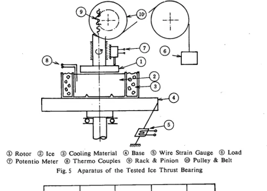
As the results of experiments shown in Fig. 5 ,
the author obtained the melting
velocity
of the ice stator to be about 0.25こ0.7 5mm/s
as shown in Fig. 6.
①Rotor ②Ice ③Cooling
Material ④Base ⑥Wire
StrainGauge ⑥Load
⑦Potentio Meter ⑧Thermo
Couples ⑨Rack
& Pinion ⑩Pulley & Belt
Fig.5 Aparatus of the Tested Ice Thrust Bearing
4.0 l 3.0 2.0 § 1.0 0 . 0 一一15℃ l l R、 0 25.25kg -ロ 60.74kg φ 42.62kg ’ χ 45.30kg , /
8
X
□ □φ 1.0 2.0 N 3.0 4。0×103‘ rpmThis value could be estimated as the satisfactorylow velocity of the industrialice bearing
with the regenerating system.
7 Conclusion
In order to find out the melting and seizure mechanism
of melting bearing and of the first
step techniques of the development
as an
example
of regenerating systems, the author
tried one simple experiment.
Then,
it was concluded
that the ice bearing system can be
useful for industrialapplication which is necessary to continue the designate life forever.
In the futuてe.stepby step, we should study the analysis of biomechanical regenerating
system.
1 )
References
Lavrovv. V., Deformation and Strength of Ice, Israel Program for Scientific Translations (Translated from Russian), Jerusaleum (1971). ‘
2) Lea J. F. and Stegall R. D. , A Two・Dimentional T・heory of Temperature and Pressure Effects on Ice Melting Rates with a Heated Plate. ASME, Ser・ C, 95- 4 (1973-11), 571. ・ Kamiyama S・,Inertia Effects in MHD Hydrostatic Thrリst Bearing (Report 2). The R・
of the Institute of High Speed Mechanics, Japan, 22 (1970), 48.
3) Kamiyama S., Inertia Effects in MHD Hydrostatic Thrりst Bearing (Report 2). The Reports 4) Wakahama G. Models of Dislocations in Ice Crystal. Low Temperature Science, Sef. A-16 (1957- 7), 227.
5) Yoshida Z., A Thermodynamical Theory about the Vapour Pressure and the Melting Point of Ice under Elastic Strain Low Temperature Science, Ser.A-20. (1962), 2.