Effect of alkyl substituents: 5,15-bis(trimethylsilylethynyl)- vs. 5,15-bis(triisopropylsilylethynyl)-tetrabenzoporphyrins and their metal complexes
25
0
0
全文
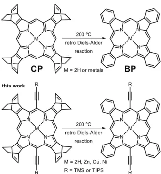
(2) INTRODUCTION Organic semiconducting materials have attracted much attention for the development of organic electronics such as organic thin-film transistors (OTFTs) and organic solar cells (OSCs). These organic electronic devices are expected to be flexible, light-weight, large area and low cost. Recently, high mobilities of over 10 cm2.V–1.s–1 have been attained in OTFTs, which are close to or over the performances of amorphous silicon devices [1, 2]. The power-conversion efficiencies of OSCs have been reported to reach almost 10% with single and tandem systems using polymers as active layers [3]. Tetrabenzoporphyrin (BP) has been reported as one of the excellent organic semiconducting materials. However, the solubility of BP is low in common organic solvents, and thus BP is not compatible with solution-based deposition processes. In order to apply BP to solution-process, Ono and his colleagues have developed a soluble precursor of BP, bicyclo[2.2.2]octadiene-fused (or annulated) porphyrin (CP), which is soluble in common organic solvents such as chloroform, toluene and chlorobenzene [4]. The precursor CP can be quantitatively converted to BP upon heating through the retro Diels–Alder reaction (Fig. 1) in solution and in the solid state without chemical reagents and purification. This thermal conversion method thus has allowed us not only to synthesize π-expanded porphyrins and related compounds [5], phthalocyanines [6], BODIPYs [7], isothianaphthenes [8], thioindigo [9] and acenes [10], but also to apply the materials to solution-processed OTFTs and OSCs. Ono, Kanicki, and coworkers have achieved a carrier mobility of 0.1 cm2.V–1.s–1 in a top-gate-bottom-contact OTFT device [11]. In addition, the precursor method enables fabrication of multi-layer organic films by solution process owing to the insolubilization of thin films after the thermal conversion. Using this “precursor approach”, Nakamura et al. fabricated p–i–n-type OSC devices based on BP as p-type material and bis(dimethylphenylsilylmethyl)[60]fullerenes (SIMEF) as n-type material to achieve the maximum photo-conversion efficiency (PCE) of 5.2% [12]. More recently, we have reported the synthesis of a BP– fullerene dyad for use as the inter (i)-layer material in p–i–n-type OSCs, in which we obtained PCEs up to 1.98% [13]. To improve the performance of organic electronic devices, molecular design of semiconducting materials is among the most important considerations. Pentacene is one of the most promising organic semiconducting materials showing good carrier mobilities of over 1 cm2.V–1.s–1 in OTFT devices, but it is hardly soluble in common organic solvents and unstable in ambient conditions. In contrast, 6,13-triisopropylsililethynyl-pentacene (TIPS-PEN) represents a good solubility and chemical stability owing to the introduction of the bulky triisopropylsilyl (TIPS)-ethynyl groups to the most reactive 6,13-positions. The pristine pentacene packs to form a herringbone motif, while TIPS-PEN forms a twodimensional-slipped-stack column structure [14]. TIPS-PEN-based OTFTs show superior carrier mobilities of up to 11 cm2.V–1.s–1 in solution-processed single-crystalline film [15]. Motivated by these results, various TIPS and related trialkylsilyl substituted acene derivatives have been developed as organic FET materials [16]. Based on these precedent contributions, we have designed and synthesized 5,15-bis(trimethylsilylethynyl) tetrabenzporphyrin (TMS-H2BP), 5,15-bis(triisopropylsilylethynyl)tetrabenzporphyrin (TIPS-H2BP) and their zinc complexes [17]. Trialkylsilylethynyl groups were introduced to the 5- and 15-positions of BP to expand π-conjugation effectively. TMS-H2BP and TIPS-H2BP were prepared by the retro Diels–Alder reaction of BCOD-fused 5,15bis(trimethylsilylethynyl)porphyrin (TMS-H2CP) and 5,15-bis(triisopropylsilylethynyl)porphyrin (TIPS-H2CP), respectively. The absorption of TMS-H2BP is redshifted as compared to BP and its absorption edge reaches 710 nm. Such a redshift is favorable for OSC materials, and a similar redshift was observed for TIPS-H2BP. At the same time, the solubility and crystal structures are different depending on the introduced substituent. Herein, we will describe the synthesis, optical properties, electrochemical properties and crystal structures of zinc(II), copper(II) and nickel(II) complexes of TMS-H2BP and TIPS-H2BP in order to discuss the substituent effect of trimethylsilyl (TMS) and TIPS.
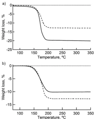
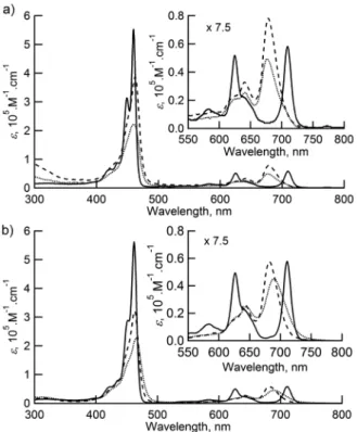
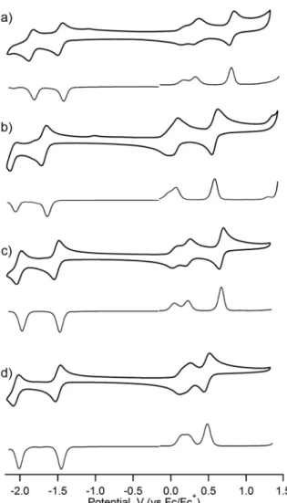
(3) groups on BP. The performances of OTFT and bulk heterojunction (BHJ) OSC devices of TMS-H2BP, TIPS-H2BP and their zinc and copper complexes as p-type materials and [6,6]-phenyl C71 butyric acid methyl ester (PC71BM) as an n-type material will be also discussed.. RESULTS AND DISCUSSION Synthesis and characterization of TMS-BP and TIPS-BP metal complexes TMS-H2CP, TMS-H2BP, TIPS-H2CP and TIPS-H2BP and the corresponding zinc(II) complexes were prepared according to the literature [17a–c]. The synthesis of metal complexes of TMS-BP and TIPS-BP is shown in Scheme 1. The copper and nickel complexes of TMS-CP and TIPS-CP were synthesized from TMS-H2CP and TIPS-H2CP by general metal insertion methods. TMS-H2CP and TIPS-H2CP were reacted with Cu(OAc)2·H2O in CHCl3 and MeOH to give TMS-CuCP in 84% and TIPS-CuCP in 91% yields. The nickel complexes were also prepared from TMSH2CP and TIPS-H2CP through the reactions with Ni(OAc)2·4H2O in CHCl3 and MeOH, by which TMS-NiCP and TIPS-NiCP were obtained in 87% and 93% yields, respectively. The thermal conversion of copper and nickel complexes of TMS-CP and TIPS-CP was analyzed by thermogravimetric analysis (TGA) with a heating rate of 10 ºC.min–1 under a nitrogen atmosphere (Fig. 2). The mass loss of all metal complexes started atf around 150 ºC and finished at around 200 ºC. The observed mass loss of 12.8% for TMS-CuCP is in agreement with the calculated value of 12.8% for the loss of the four ethylene units per molecule. The mass loss for TMS-NiCP (12.9%) and TIPS-NiCP (10.2%) are also in agreement with the calculated values of 12.8% and 10.8%. On the other hand, the observed mass loss of TIPS-CuCP is 19.7%, which is in consistent with the loss of four ethylene molecules and a chloroform molecule per one TIPS-CuCP molecule (calculated value: 19.9%). The TGA results suggested that the precursor CPs could be converted to the corresponding BPs quantitatively by heating at 200 ºC in the solid state. The TMS-CuBP and TMS-NiBP exhibited low solubilities in common organic solvents, while TIPS-CuBP and TIPS-NiBP were soluble in halogenated solvents, THF and toluene. The structures of TMS-NiBP and TIPS-NiBP were characterized by 1H and 13. C NMR specrtroscopy, high-resolution mass spectrometry (HRMS) and single-crystal X-ray diffraction (XRD). analysis. TMS-CuBP and TIPS-CuBP were also characterized by HRMS and single-crystal XRD analysis. Photophysical and electrochemical properties The UV–vis absorption spectra of TMS-BPs in DMF and TIPS-BPs in CH2Cl2 are shown in Fig. 3. The obtained optical data are summarized in Table 1. We previously reported the absorption of TMS-H2BP, TMS-ZnBP [17c], TIPS-H2BP and TIPS-ZnBP [17a] in CH2Cl2. TMS-H2BP shows peak top of the Soret-band at 462 nm and the longest wavelength of Q-band at 711 nm and TIPS-H2BP shows at 460 and 710 nm. The absorption spectra of TMS-BPs and TIPS-BPs are redshifted from TMS-CPs and TIPS-CPs because of the π-expansion (Figs. S1). The Soret band peaks of metal porphyrins are almost the same as those of free-base porphyrins, but the longest Q-band peaks are blueshifted compared to the free-base porphyrins. To investigate the electrochemical properties of TIPS-H2BP and its metal complexes, we performed the cyclic voltammetry (CV) and differential pulse voltammetry (DPV) in CH2Cl2 with 0.1 M n-Bu4NPF6 as an electrolyte at room temperature. The results are shown in Fig. 4 and Table 1. The electrochemical properties of TMS-BP metal complexes could not been measured because of the insolubility. The reversible three oxidation peaks were observed for TIPSH2BP (0.18, 0.22 and 0.48 V vs. ferrocene/ferrocenium), TIPS-CuBP (0.06, 0.23 and 0.68 V), TIPS-NiBP (0.17, 0.22 and 0.37 V) and two oxidation peaks were observed for TIPS-ZnBP (0.07 and 0.59 V) while the reversible two reduction peaks were observed for TIPS-H2BP (–1.42 and –1.81 V), TIPS-CuBP (–1.34 and –1.48 V), TIPS-NiBP (–.
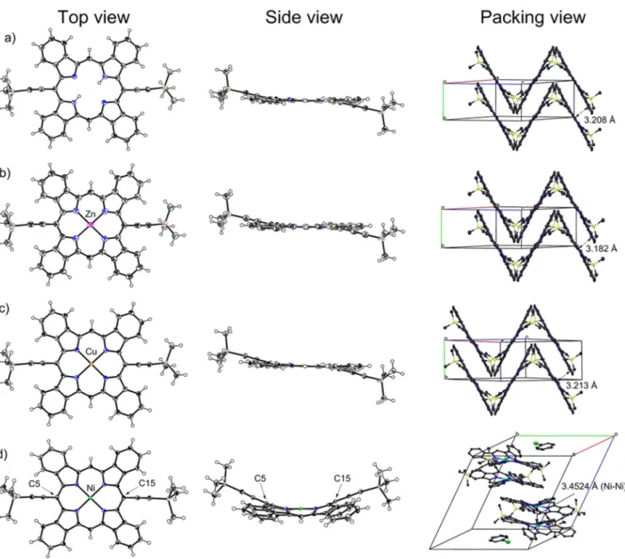
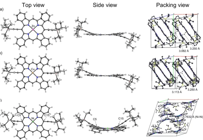
(4) 1.30 and –2.01 V) and TIPS-ZnBP (–1.64 and –2.06 V). The first and second oxidation peaks of TIPS-H2BP, TIPSCuBP or TIPS-NiBP correspond to one electron oxidation in total, and the ratio of the two peaks changes depending on the concentration of the sample (Fig. S2). We assume that the first oxidation potential belongs to the formation of dimeric cation radical and the second peak is corresponding to the oxidation to monomeric cation. The third peak of TIPS-H2BP, TIPS-CuBP and TIPS-NiBP is one electron oxidation and corresponds to the second oxidation of BP compounds. This phenomenum was also observed for a BP-C60 dyad [13]. Crystal structures of TMS-BP and TIPS-BP metal complexes Single crystals of TMS-H2BP, TMS-ZnBP, TMS-CuBP and TMS-NiBP suitable for X-ray analysis were obtained by recrystallization in o-dichlorobenzene (TMS-H2BP, TMS-ZnBP and TMS-CuBP) or slow diffusion of heptane into a chlorobenzene solution (TMS-NiBP). TMS-H2BP adopts a sigmoidal-shape in the single-crystalline state and is packed in one-dimensional slipped-stack structures (Fig. 5a). The neighboring columns are arranged to form a herringbone motif which is different from TIPS-H2BP which form a one-dimensional columnar array. The distance associated with the π–π stacking between porphyrin cores is 3.208 Å. TMS-ZnBP and TMS-CuBP afforded similar herring-bone-type packing structures comprising of sigmoidal-shaped molecules. The shortest distance between neighboring porphyrin cores are 3.182 Å for TMS-ZnBP and 3.213 Å for TMS-CuBP (Figs. 5b and 5c). On the other hand, the BP framework in TMS-NiBP adopts a saddle-shaped conformation reflecting the small radius of nickel(II) atom in comparison with the cavity size of porphyrin (Fig. 5d). The intramolecular C5–C15 distances are 6.657(2) and 6.656(3) Å, and the TMS substituents orient to the same direction so that the overall molecular conformation is Vshaped when viewed from the side. Molecules of TMS-NiBP form a face-to-face dimeric motif, in which the two molecules are stacked orthogonally with their curved porphyrin surfaces fitting well to each other. Two chlorobenzene molecules are located in the unit cell to occupy the space between the face-to-face dimeric motifs. The TMS groups of each molecule are oriented toward its partner in the dimeric structure. The associated Ni–Ni distance in the dimer is 3.4524(3) Å. Neighboring dimers are related by an inversion center to form a slipped-stack structure extending along the <0 1 1> direction. Single crystals of TIPS-ZnBP and TIPS-CuBP were obtained by slow diffusion of heptane into a chlorobenzene solution and by slow diffusion of methanol into a chloroform solution, respectively (Figs. 6a and 6b). TIPS-ZnBP and TIPS-CuBP have a planar benzoporphyrin core and two ethynyl groups bent from the benzoporphyrin plane sigmoidally as similar to the case of TIPS-H2BP. In the packing structures of TIPS-ZnBP and TIPS-CuBP, molecules form a triad-like structures where the molecules are stacked orthogonally. The minimum plane-to-plane distance of each molecule is 3.250 Å for both TIPS-ZnBP and TIPS-CuBP, which distance is shorter than that of TIPS-H2BP (3.295 Å) [17a]. The triad units are packed parallel to make one-dimensional slip-stacked structures with the plane-to-plane distances of 3.082 Å for TIPS-ZnBP and 3.113 Å for TIPS-CuBP, respectively. Single crystals of TIPS-NiBP were obtained by slow diffusion of ethanol into a 1,2-dichloroethane solution. The crystal structure of TIPS-NiBP is similar to TMS-NiBP (Fig. 6c). TIPS-NiBP molecules show a saddle-shaped comformation with the intramolecular C5–C15 distances are 6.645(2) or 6.671(2) Å, and form a face-to-face dimeric motif. The curved porphyrin surfaces are fitted well to each other, but TIPS groups of each molecule are oriented against its partner in the dimeric structure. The associated Ni–Ni contact is 3.7632(3) Å. Fabrication and evaluation of OTFTs We have fabricated OTFT devices utilizing the free-base and the corresponding zinc(II) and copper(II) complexes of TMS-BP and TIPS-BP to investigate the effect of the substituent structure and metalation on the performance of OTFT.
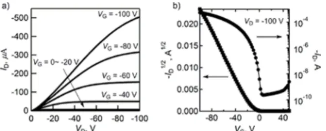
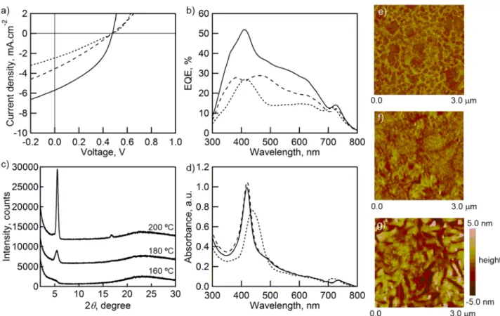
(5) devices. The TMS-BP or TIPS-BP films were fabricated by heating thin-films which were fabricated by spin-coating of the precursors, TMS-CP or TIPS-CP, on n-doped Si substrates followed by heating. Bottom-gate-top-contact structures were by evaporating the Au source and drain electrodes on the organic film. Performance parameters of each OTFT device estimated from the saturation regime are summarized in Table 2. The best performance was obtained with TMS-H2BP, which gave a hole mobility (µFET) of 0.11 cm2.V–1.s–1 with an on/off ratio was 2.4 × 10⁶. The output and transfer curves of this device are shown in Fig. 7. The XRD patterns of the films heated at 180 °C suggested the edgeon configuration for these films (Fig. S6) Fabrication and evaluation of OSCs We have also fabricated OSCs utilizing the free-base and the corresponding zinc(II) and copper(II) complexes of TMS-BP and TIPS-BP as p-type materials with PC71BM as n-type material to investigate the effect of the substituent structure and metalation on the performance of OSC devices. To fabricate TMS- and TIPS-BP-based OSCs, we have initially investigated the ionization energy of thin-films on ITO-glass substrates by photoelectron spectroscopy in air to estimate the HOMO levels (EHOMO) of materials. The ionization energies are 5.22 eV for TMS-H2BP, 5.25 eV for TMSZnBP, 5.10 eV for TMS-CuBP, 5.24 eV for TIPS-H2BP, 5.37 eV for TIPS-ZnBP and 4.88 eV for TIPS-CuBP (Table 1 and Fig. S3). The LUMO levels (ELUMO) were estimated by adding the optical bandgaps to the IPs. The optical bandgaps were determined from the absorption onset of the thin-films (Table 1 and Fig. S4). The LUMO levels were calculated to be –3.61 eV for TMS-H2BP, –3.62 eV for TMS-ZnBP, –3.49 eV for TMS-CuBP, –3.61 eV for TIPSH2BP, –3.76 eV for TIPS-ZnBP and –3.26 eV for TIPS-CuBP. The typical OPV structure was glass/ITO/PEDOT:PSS (30 nm)/TMS- or TIPS-BP:PC71BM/BCP (7 nm)/Al (100 nm). Active layers were deposited by spin-coating (2500 rpm for TMS-CPs or 800 rpm for TIPS-CPs) of a solution containing a precursor (TMS-CPs or TIPS-CPs) and PC71BM (1:1 (w/w)) in a chloroform solution for TMS-CPs (20 mg.mL–1) or a mixture of chloroform:chlorobenzene (1:1(v/v)) solution for TIPS-CPs (10 mg.mL–1). Each the deposited film was then heated at 160, 180 or 200 °C for 30 min to generate the corresponding benzoporphyrin in situ. It is known that the thermal conversion temperature largely affects the device properties because of the change in film morphology and crystallinity [19]. The J–V curves of the devices having TMS-H2BP:PC71BM or TIPS-H2BP:PC71BM as active layer are shown in Figs. 8a and 9a. The values of short circuit current density (JSC), open circuit voltage (VOC), fill factor (FF), and power conversion efficiency (PCE) are summarized in Table 3. When the TMS-H2BP:PC71BM film was annealed at 160 ºC, a PCE of 0.33% was obtained. By increasing the annealing temperature to 180 ºC, PCE was improved to 1.09% with JSC = 5.07 mA.cm–2, VOC = 0.48 V and FF = 0.40. However, further increase of the annealing temperature to 200 ºC resulted in a decreased PCE of 0.47%. The TIPS-H2BP:PC71BM system showed a similar tendency to TIPS-H2BP:PC71BM and the highest PCE of 1.02% was obtained by annealing at 180 ºC associated with JSC = 5.22 mA.cm–2, VOC = 0.61 V and FF = 0.28. The other annealing temperatures (160 and 200 ºC) gave lower PCE values (0.57% and 0.19%). The TMSH2BP:PC71BM and TIPS-H2BP:PC71BM devices are comparable in JSC and FF values, while the VOC values are considerably different. The external quantum efficiency (EQE) (Figs. 8b and 9b) of the devices prepared by heating at 180 ºC is higher as compared to those obtained by heating at 160 and 200 ºC, although the absorption spectra of the blend films are similar between the 180 and 200 °C devices (Figs. 8d and 9d). Active-layer structures of these devices were investigated by out-of-plane XRD and tapping-mode atomic force microscopy (AFM). Figs. 8c and 9c show XRD patterns of the TMS-H2BP:PC71BM and TIPS-H2BP:PC71BM blend films annealed at 160, 180, and 200 ºC. Diffraction peaks are observed at 2θ = 5.43º and 5.44º for the TMSH2BP:PC71BM blend films annealed at 180 and 200 ºC, respectively. In the case of TIPS-H2BP:PC71BM films annealed at 180 and 200 ºC, diffraction peaks are observed at 5.45º and 5.50º, respectively. These peaks correspond to.
(6) the (001) diffraction of TIPS-H2BP considering the corresponding peak observed for a TIPS-H2BP neat film (Fig. S6b). The peak intensity increased with raising the annealing temperature from 180 to 200 ºC. The film annealed at 160 ºC showed no specific diffraction peaks. This observation implies that TMS-H2BP and TIPS-H2BP films become crystalline over 180 ºC, while the annealing at 160 ºC affords amorphous films. The similarity between the absorption spectra of the films annealed at 180 and 200 ºC is in agreement with the results of XRD. Fig. 8e–g and Fig. 9e–g show the AFM images of TMS-H2BP:PC71BM and TIPS-H2BP:PC71BM blend films. The TMS-H2BP:PC71BM blend films show large domains at all annealing temperatures. These phase separation is promoted by increasing the annealing temperature. In particular, domains as large as 1 µm and large cracks were observed for the film annealed at 200 ºC. On the contrary, the TIPS-H2BP:PC71BM blend films annealed at 160 and 180 ºC show smooth surface with smaller roughness, indicating the formation of micro-domains. In the case of the film annealed at 200 ºC, cracks were found on the surface. As the results of XRD, the higher crystallinity films of TMS-H2BP and TIPS-H2BP were obtained by annealing at 200 ºC, and these crystalline films have large grains. In general, the organic materials have the exciton diffusion length within 20–30 nm. To attain the high PCE values, efficient charge separation is necessary and the grain size should be in the same order as the exciton diffusion length. Therefore, the larger grain size leads to lower PCEs [20]. The film annealed at 180 ºC has the highest PCE owing to the smooth surface and moderate crystallinity of TMSH2BP and TIPS-H2BP. These results indicate that the bulky TIPS groups and moderate annealing temperature inhibited the growth of large domains in blend films with PC71BM. The OSC using TMS-ZnBP or TIPS-ZnBP as p-type material with PC71BM as an n-type material were also fabricated. The results are summarized in Table 3, Figs. S7a and S7b. TMS-ZnBP and TIPS-ZnBP showed the best performances with the annealing temperature at 180 ºC. The JSC and FF values of TMS-ZnBP were improved compared to TMS-H2BP, and a PCE of 1.49% was attained. The VOC value of TMS-ZnBP was comparable to TMSH2BP, although the EHOMO of TMS-ZnBP is lower than that of TMS-H2BP. The increase in JSC is probably due to form the face-on π-π stacking of TMS-ZnBP in TMS-ZnBP:PC71BM films (180 and 200 °C). This is indicated by the observation peaks at 2θ = 28.5 and 28.6° (d = 3.13 and 3.12 Å) in the XRD patterns as shown in Fig. S6b. These peaks correspond to the distance of π–π stacking as supported by the crystal structure of TMS-ZnBP (Fig. 5b). TIPS-ZnBP also showed the improvement of the PCE compared to TIPS-H2BP, and the 1.13% of PCE was attained. The OSC using TMS-CuBP or TIPS-CuBP as p-type material with PC71BM as an n-type material were also fabricated. The copper porphyrins are known to exhibit short fluorescence lifetimes compared with the free-base porphyrins and are not suitable for the OSC, since the exciton diffusion length becomes shorter [21]. The results are summarized in Table 3 and Figs. S7c and S7d. The best annealing temperature was 160 ºC and the PCE values are 0.72 and 0.86% for TMS-CuBP and TIPS-CuBP, respectively. TMS-CuBP and TIPS-CuBP single films are crystalline (Fig. S4f), but the crystallinity of the blend films with PC71BM are lower than H2BP and ZnBP films. The AFM images of TMS-CuBP:PC71BM blend films showed larger domains for the films annealed at 180 and 200 °C, although the XRD patterns showed small peaks. The AFM images of TIPS-CuBP:PC71BM blend films look smooth and amorphous. These will be one of the reasons why the JSC of the devices with TMS-CuBP and TIPS-CuBP are relatively low.. CONCLUSION We have succeeded in the preparation of the TMS- and TIPS-BP metal complexes by the retro Diels–Alder reaction of the corresponding precursors, TMS- and TIPS-CP, respectively. TMS- and TIPS-BPs exhibited very similar absorption properties with little effects from the TMS- and TIPS-groups. We revealed that the two alkylsilyl groups induced the different crystal structures. TMS-H2BP, TMS-ZnP and TMS-CuBP showed the herringbone-type packing.
(7) structures, while TIPS-H2BP, TIPS-ZnP and TIPS-CuBP showed the one-dimensional slip stacked structures. OTFT devices of these benzoporphyrins were fabricated by solution process and the best performance was obtained for TMSH2BP with a µFET of 0.11 cm2.V–1.s–1. The BHJ-type OSCs based on TMS-H2BP or TIPS-H2BP with PC71BM were also fabricated. The best performance among these OSC systems was obtained with a TMS-H2BP:PC71BM blend film annealed at 180 ºC with a PCE of 1.09%. The film structures evaluated by the AFM and XRD measurements suggested the critical effect of the annealing temperature to the film structure and thus the device performance. By annealing at 180 ºC, the crystallinity of TMS-H2BP and TIPS-H2BP was increased as opposed to annealing at 160 °C which resulted to the formation of amorphous films. However, annealing at 200 ºC promoted large phase separation and cracking to provide the considerably lower PCEs. The films annealed at 180 ºC have moderate crystallinities and smooth surfaces, and are suitable for OSC devices in the case of TMS-H2BP and TIPS-H2BP. The BHJ OSC devices based on zinc(II) and copper(II) complexes as p-type materials were also fabricated. The blend films of TMS-ZnBP or TIPS-ZnBP and PC71BM showed better molecular orientations, and afforded improved of the OSC performances as compared to free-base and copper(II) complex. Investigations of a wider variety of benzoporphyrin derivatives with different substituents are in progress, with the aim of achieving further improved performance in benzoporphyrin-based OSCs.. EXPERIMENTAL General 1. H NMR and. 13. C NMR spectra were recorded on a JEOL ECX 400P spectrometer at ambient temperature using. tetramethylsilane as an internal standard. ESI mass spectra were measured on a JEOL JMS-700 spectrometer. UV–vis spectra were measured on a JASCO UV/VIS/NIR spectrophotometer V-570. All solvents and chemicals were reagent grade quality, obtained commercially and used without further purification. For spectral measurements, spectral grade solvents were purchased from Nacalai Tesque Inc. X-ray crystallographic data were recorded at 103 K (TMS-H2BP, TMS-ZnBP, TMS-CuBP, TMS-NiBP) and 123 K (TIPS-CuBP, TIPS-NiBP) on a Rigaku CCD detector (Saturn 724) mounted on a Rigaku rotating anode X-ray generator (Micro-Max-007HF) using Mo-Kα radiation from the corresponding set of confocal optics. The structures were solved by direct methods and refined on F2 by full-matrix least-squares using the CrystalClear and SHELXS-2000 program. Ionization potential was determined by atmospheric photoelectron spectroscopy (Riken Keiki, AC-3). Materials TMS-H2CP [17b], TMS-ZnCP, TMS-ZnBP [17c], TIPSH2CP, TIPS-ZnCP and TIPS-ZnBP [17a] were prepared according to the procedures described in literature. PC71BM was purchased from Luminescence Technology Corp. and used as received. Thermogravimetric. analysis were. performed on a Seiko Thermal Analyser Exstar TG/DTA 6200. X-ray diffraction (XRD) was recorded on a Rigaku Smartlab system. AFM image were recorded on Bruker D8 and Veeco Dimension Icon. Synthesis [5,15-Bis(trimethylsilylethynyl)tetrakis(bicycle[2,2,2]octadieno)porphyrinato]copper(II) (TMS-CuCP) A saturated solution of Cu(OAc)2·H2O in methanol (18 mL) was added to a solution of TMS-H2CP (0.118 g, 0.145 mmol) in CHCl3 (50 mL). After stirring for 2 h at room temperature, the reaction mixture was poured into water and extracted with CHCl3. The organic layer was washed with water and brine, then dried over Na2SO4, and the solvent was removed under a reduced pressure. The residue was purified by recrystallization CHCl3 / MeOH to give TMS-CuCP as purple crystals in 84% (0.106 g, 0.121 mmol). UV–vis (CH2Cl2): λmax, nm (ε × 104): 431 (39.9), 563 (1.47), 591 (2.23),.
(8) 605 (2.31); HRMS (ESI): m/z = 876.3119, calcd. for C54H53N4CuSi2: 876.3105 [M + H]+. Elemental analysis: Anal. calcd for C54H52CuN4Si2: C, 73.98; H, 5.98; N, 6.39. Found: C, 73.92; H, 5.97; N, 6.41. [5,15-Bis(trimethylsilylethynyl)tetrakis(bicycle[2,2,2]octadieno)porphyrinato]nickel(II) (TMS-NiCP) A saturated solution of Ni(OAc)2·4H2O in methanol (10 mL) was added to a solution of TMS-H2CP (0.113 g, 0.138 mmol) in CHCl3 (50 mL) at room temperature. The mixture was refluxed for 3 h. After being cooled to room temperature, the reaction mixture was poured into water and extracted with CHCl3. The organic layer was washed with water and brine, then dried over Na2SO4, and the solvent was removed under a reduced pressure. The residue was purified by recrystallization (CHCl3/MeOH) to give TMS-NiCP as purple crystals in 87% (105 mg, 0.120 mmol). 1H NMR (400 MHz; CDCl3; Me4Si): δH, ppm 9.55 (m, 2H), 6.97 (m, 8H), 6.35 (m, 4H), 5.39 (m, 4H), 2.04–1.83 (m, 16H), 0.57 (m, 18 H). 13C NMR (100 MHz; CDCl3; Me4Si): δC, ppm 206.36, 151.68, 151.65, 151.59, 150.12, 150.02, 149.98, 137.16, 136.55, 136.53, 135.75, 133.36, 133.31, 106.28, 106.26, 106.20, 106.17, 98.10, 95.33, 77.20, 50.05, 38.90, 35.87, 27.25, 27.19, 27.01, 0.27, 0.09. UV–vis (CH2Cl2): λmax, nm (ε × 104): 430 (29.6), 603 (1.95); HRMS (ESI): m/z = 871.3168, calcd. for C54H53N4NiSi2: 871.3162 [M + H]+. Elemental analysis: Anal. calcd for C54H52N4NiSi2·1/2 H2O: C, 73.63; H, 6.06; N, 6.39. Found: C, 73.68; H, 5.96; N, 6.60. [5,15-Bis(triisopropylsilylethynyl)tetrakis(bicycle[2,2,2]octadieno)porphyrinato]copper(II) (TIPS-CuCP) A solution of Cu(OAc)2·H2O (407 mg, 2.04 mmol) in methanol (15 mL) was added to a solution of TIPS-H2CP (101 mg, 0.103 mmol) in CHCl3 (50 mL). After stirring for 2 h at room temperature, the reaction mixture was washed with saturated NaHCO3 aq., and water. The mixture was then dried over Na2SO4, and the solvent was removed under reduced pressure. The residue was purified by recrystallization (CHCl3/MeOH) to give TIPS-CuCP as purple crystals in 91% (97.7 mg, 0.0935 mmol). UV–vis (CH2Cl2): λmax, nm (ε × 104): 431 (41.1), 562 (1.74), 592 (2.64), 604 (2.47); HRMS (ESI): m/z = 1044.4984, calcd. for C66H77Cu N4Si2: 1044.4983 [M + H]+. [5,15-Bis(triisopropylsilylethynyl)tetrakis(bicycle[2,2,2]octadieno)porphyrinato]nic-kel(II) (TIPS-NiCP) A solution of Ni(OAc)2·4H2O (0.507g, 2.04 mmol) in methanol (15 mL) was added to a solution of TIPS-H2CP (101 mg, 0.103 mmol) in CHCl3 (50 mL) at room temperature. The mixture was refluxed for 3 h. After being cooled to room temperature, the reaction mixture was washed with saturated NaHCO3 aq., and water. The mixture was then dried over Na2SO4, and the solvent was removed under reduced pressure. The residue was purified by recrystallization (CHCl3/MeOH) to give TIPS-NiCP as purple crystals in 93% (98.6 mg, 0.0948 mmol). 1H NMR (400 MHz; CDCl3; Me4Si): δH, ppm 9.51 (m, 2H), 6.94 (m, 8H), 6.41 (m, 4H), 5.37 (m, 4H), 2.10–1.76 (m, 16H), 1.53–1.42 (m, 6H), 1.36– 1.33 (m, 36H). 13C NMR (100 MHz; CDCl3; Me4Si): δC, ppm 151.91, 151.87, 151.83, 151.80, 151.77, 150.55, 150.52, 150.50, 137.19, 137.15, 136.40, 136.38, 136.36, 135.90, 135.86, 135.82, 135.78, 133.06, 133.03, 107.28, 104.73, 104.66, 98.14, 95.30, 95.26, 38.66, 38.63, 35.90, 35.88, 27.23, 27.20, 27.15, 18.86, 11.78. UV–vis (CH2Cl2): λmax, nm (ε × 104): 432 (23.8), 594 (1.65), 601 (1.62). HRMS (ESI): m/z = 1039.5042, calcd. for C66H77N4NiSi2: 1039.5040 [M + H]+. 5,15-Bis(trimethylsilylethynyl)tetrabenzoporphyrin (TMS-H2BP) TMS-H2BP was prepared according to the procedures described in literature [17c]. Crystallographic data: C46H38N4Si2, Mw = 702.98, monoclinic, space group C2/c, a = 37.5744(10), b = 6.47957(16), c = 15.2073(4) Å, β = 100.5070(10), V = 3640.37(17) Å3, T = 103 K, Z = 4, R1 = 0.0478, wR2 = 0.1282, GOF = 1.064, CCDC NO. 1031711. [5,15-Bis(trimethylsilylethynyl)tetrabenzoporphyrinato]zinc(II) (TMS-ZnBP) TMS-ZnBP was prepared according to the procedures described in literature [17c]. Crystallographic data: C46H36N4Si2Zn, Mw = 766.34, monoclinic, space group C2/c, a = 37.029(3), b = 6.5615(4), c = 15.1517(4) Å, β = 100.2749(15), V = 3610.6(4) Å3, T = 103 K, Z = 4, R1 = 0.0596, wR2 = 0.1596, GOF = 1.030, CCDC NO. 1039260..
(9) [5,15-Bis(trimethylsilylethynyl)tetrabenzoporphyrinato]copper(II) (TMS-CuBP) TMS-CuCP was heated at 200 °C for 1 h in a sample tube under reduced pressure to give TMS-CuBP quantitatively. UV–vis (DMF): λmax, nm (ε × 104): 462 (38.6), 641 (3.27), 678 (7.81). HRMS (MALDI): m/z = 763.1769, calcd. for C46H36CuN4Si2: 763.1775 [M]+. Crystallographic data: C46H36CuN4Si2, Mw = 764.54, monoclinic, space group C2/c, a = 37.0934(9), b = 6.5331(2), c = 15.2433(4) Å, β = 101.1999(7)º, V = 3623.6(2) Å3, T = 103 K, Z = 4, R1 = 0.0410, wR2 = 0.1064, GOF = 1.069, CCDC NO. 1031710. [5,15-Bis(trimethylsilylethynyl)tetrabenzoporphyrinato]nickel(II) (TMS-NiBP) TMS-NiCP was heated at 200 °C for 1 h in a sample tube under reduced pressure to give TMS-NiBP quantitatively. 1H and 13C NMR spectra could not record because of the low solubility. UV–vis (DMF): λmax, nm (ε × 104): 462 (30.0), 642 (2.53), 677 (4.94). HRMS (MALDI): m/z = 758.1827, calcd. for C46H36N4NiSi2: 758.1832 [M]+. Crystallographic data: 2(C46H36N4NiSi2)·C6H5Cl, Mw = 3146.27, triclinic, space group P-1, a = 13.9807(3), b = 17.5488(4), c = 18.7217(4) Å,. α = 63.4700 (7), β = 76.3869(7), γ = 67.1216(7)º, V = 3775.7(2) Å3, T = 103 K, Z = 1, R1 = 0.0352, wR2 = 0.0955, GOF = 1.091, CCDC NO. 1031712. [5,15-Bis(triisopropylsilylethynyl)tetrabenzoporphyrinato]zinc(II) (TIPS-ZnBP) TIPS-ZnBP was prepared according to the procedures described in literature [17a]. UV–vis (THF): λmax, nm (ε × 104): 468 (61.7), 632 (1.96), 647 (1.87), 681 (9.96). Crystallographic data: C174H180N12Si6Zn3, Mw = 2083.95, triclinic, space group P-1, a = 12.9138(2), b = 15.6986(3), c = 19.0118(4) Å, α = 101.5960(10), β = 108.2190(10), γ = 97.6090(10), V = 3506.44(11) Å3, T = 103 K, Z = 1, R1 = 0.0476, wR2 = 0.1275, GOF = 1.069, CCDC NO. 1040808. [5,15-Bis(triisopropylsilylethynyl)tetrabenzoporphyrinato]copper(II) (TIPS-CuBP) TIPS-CuCP was heated at 200 °C for 1 h in a sample tube under reduced pressure to give TIPS-CuBP quantitatively. UV–vis (CH2Cl2): λmax, nm (ε × 104): 682 (5.75), 642 (2.64), 463 (32.0), 314 (1.75). HRMS (ESI): m/z = 954.3551, calcd. for C58H60CuN4Si2: 954.3550 [M]+. Crystallographic data: C58H60CuN4Si2, Mw = 932.82, triclinic, space group P1, a = 12.9931(3), b = 15.6209(4), c = 19.0424(4) Å, α = 101.3190(10), β = 108.7220(10), γ = 97.5070(10)º, V = 3510.32(14) Å3, T = 123 K, Z = 3, R1 = 0.0410, wR2 = 0.1006, GOF = 1.070, CCDC NO. 1031708. [5,15-Bis(triisopropylsilylethynyl)tetrabenzoporphyrinato]nickel(II) (TIPS-NiBP) TIPS-NiCP was heated at 200 °C for 1 h in a sample tube under reduced pressure to give TIPS-NiBP quantitatively. 1H NMR (400 MHz; CDCl3; Me4Si): δH, ppm 9.98 (m, 4H), 8.97 (m, 2H), 8.71 (m, 4H), 7.91 (m, 4H), 7.81 (m, 4H), 1.53– 1.43 (m, 6H), 1.38-1.32 (m, 36H).. C NMR (100 MHz; CDCl3; Me4Si): δC, ppm 138.25, 137.34, 136.58, 133.58,. 13. 126.19, 125.95, 124.66, 119.69, 108.51, 106.41, 94.18, 92.37, 18.96, 11.71. UV–vis (CH2Cl2): λmax, nm (ε × 104): 689 (4.51), 645 (2.48), 465 (22.6), 314 (2.08). HRMS (ESI): m/z = 927.3787, calcd. for C58H60N4NiSi2: 927.3788 [M + H]+. Crystallographic data: C58H60N4NiSi2, Mw = 928.01, monoclinic, space group P21/n, a = 23.6378(5), b = 16.8788(3), c = 26.1340(5) Å, β = 113.5099(7)º, V = 9561.4(3) Å3, T = 123 K, Z = 8, R1 = 0.0363, wR2 = 0.0965, GOF = 1.033, CCDC NO. 1031709. Electrochemical measurements CV and DPV measurements were conducted in a solution of 0.1 M n-Bu4NPF6 in CH2Cl2 (TIPS-H2BP) or benzonitrile (TIPS-ZnBP, TIPS-CuBP and TIPS-NiBP) with a scan rate of 100 mV.s–1 at room temperature in an argon-filled cell. A glassy carbon electrode and a Pt wire were used as a working and a counter electrode, respectively. An Ag/AgNO3 electrode was used as a reference electrode, which was normalized with the half-wave potential of ferrocene/ferrocenium cation (Fc/Fc+) redox couple..
(10) Fabrication and evaluation of organic thin-film transistor The heavily doped n-type Si substrates with 300 nm thick thermally grown SiO2 layer as the gate dielectric Si substrates were cleaned sequentially with H2O, acetone and 2-propanol in an ultrasonic bath, and treated with UVozone plasma for 20 min. Chloroform solutions of precursors (TMS-CPs or TIPS-CPs, 7 mg.mL–1) were spin coated at 1000 rpm for 40 sec on Si substrates in a nitrogen glove box, where H2O and O2 concentrations were < 0.5 ppm. TIPSCPs or TMS-CPs films were annealed at 180 ºC for 30 min. Au source and drain electrodes (70 nm) were vacuum deposited through a metal shadow mask. The channel ength (L) and width (W) were 50 μm and 5.5 mm, respectively. Transfer (ID–VG) and output (ID–VD) curves of OTFT devices were measured using an Agilent HP4155C semiconductor parameter analyzer in a glove box at room temperature. Field-effect mobility (µFET) was estimated from the saturation regime at drain voltage VDS = –100 V, using the equation: IDS=(μWCi/2L)(VG – Vth)2. (1). where IDS is the drain-source current, μ the field-effect mobility, W the channel width, L the channel length, Ci the capacitance per unit area of the gate dielectric layer, and Vth the threshold voltage. Fabrication and evaluation of organic cell The typical spin-coated BHJ devices of TIPS-H2BP or TMS-H2BP and PC71BM [ITO/PEDOT:PSS (30 nm)/TIPSH2BP:PC71BM or TMS-H2BP:PC71BM/BCP (7 nm)/Al (100 nm)] were fabricated as follows; ITO-coated glass substrates were cleaned stepwisely in Semico clean 56, water, acetone, and 2-propanol under ultrasonication for 10 min each. After the UV/O3 treatment for 20 min, the poly(3,4-ethylenedioxythiophene):poly(4-styrenesulfonate) layer (PEDOT:PSS, Clevios, Al4083) was spin-coated onto a cleaned ITO surface. After being baked at 120 °C in air for 20 min, the substrates were transferred into a nitrogen filled glove box (< 0.5 ppm O2 and H2O). TIPS-H2CP:PC71BM = 1:1 (w/w) (10 mg.mL–1 chloroform:chlorobenzene = 1:1 (v/v), 250 μl, 800 rpm) or TMS-H2CP:PC71BM = 1:1 (w/w) (20 mg.mL–1 chloroform, 250 μL, 2500 rpm) spin-coated for 40 sec. in a glove box, then heated at by the various temperatures for 30 min. followed by the continuous vacuum deposition of BCP (7 nm) and Al (100 nm). The device was then tested in air after the encapsulation in the glove box. The current–voltage (J–V) curves were measured using a Keithley 2400 source measure unit under AM 1.5G illumination at an intensity of 100 mW.cm–2 using a solar simulator (Bunko-keiki, CEP-2000TF). The external quantum efficiency (EQE) spectra were measured with a Xe lamp and monochromator using a CEP-2000 integrated system by Bunko-keiki Co. Acknowledgements This work was supported by a Grant-in-Aid (no. 25288092 and 22350083 to H.Y. and no. 25288113 to K. N.), the Green Photonics Project in NAIST and the program for promoting the enhancement of research universities in NAIST sponsored by the Ministry of Education, Culture, Sports, Science and Technology, Japan. We acknowledge the Nippon Synthetic Chem. Ind. (Osaka, Japan) for a gift of ethyl isocyanoacetate, which was used for the preparation of the starting pyrroles. REFERENCES 1. Yuan Y, Giri G, Ayzner AL, Zoombelt AP, Mannsfeld SCB, Chen J, Nordlund D, Toney MF, Huang J and Bao Z. Nat. Commun. 2014; 5: 3005..
(11) 2. Luo C, Kyaw AKK, Perez LA, Patel S, Wang M, Brimm B, Bazan GC, Kramer EJ and Heeger AJ. Nano Lett. 2014; 14: 2764–2771. 3. Kan B, Zhang Q, Li M, Wan X, Wan N, Long G, Wang Y. Yang X, Feng H and Chen Y. J. Am. Chem. Soc. 2014; 136: 15529–15532. 4. Ito S, Murashima T, Ono N and Uno H. Chem. Commun. 1998; 1661–1662. 5. a) Ono N, Yamada H and Okujima T. Handbook of Porphyrin Science, vol. 2. World Scientific: Singapore, 2010; 1–102. b) Carvalho CMBC, Brocksom TJ and Oliveira KT. Chem. Soc. Rev. 2013; 42: 3302–3317 and reference sited therein. c) Roznyatovskiy VV, Lee C-H and Sessler JL. Chem. Soc. Rev. 2013; 42: 1921–1933 and reference sited therein. d) Yamada H, Okujima T and Ono N. Chem. Commun. 2008; 2957–2974 and reference sited therein. e) Ishida S-i, Kuzuhara D, Yamada H and Osuka A. Asia. J. Org. Chem. 2014; 3: 716–722. 6. Hirao A, Akiyama T, Okujima T, Yamada H, Uno H, Sakai Y,Aramaki S, and N Ono. Chem. Commun. 2008; 39: 4714–4716. 7. a) Nakamura M, Kitatsuka M, Takahashi K, Nagata T, Mori S, Kuzuhara D, Okujima T, Yamada, H, Nakae T and Uno H. Org. Biomol. Chem. 2014; 12: 1309–1317. b) Nakamura M, Tahara H, Takahashi K, Nagata T, Uoyama H, Kuzuhara D, Mori S, Okujima T, Yamada H and Uno H. Org. Biomol. Chem. 2012; 10: 6840–6849. c) Tomimori Y, Okujima T, Yano T, Mori S, Ono N, Yamada H and Uno H. Tetrahedron 2011; 67: 3187–3193. d) Okujima T, Tomimori Y, Nakamura J, Yamada H, Uno H and Ono N. Tetrahedron 2010; 66: 6895-6900. e) Uno H, S. Ito S, Wada M, Watanabe H, Nagai M, Hayashi A, Murashima T and Ono N. J. Chem. Soc., Perkin Trans. 2000; 1: 4347–4355. 8. a) Liu Q, Kong F-T, Tetsuo O, Yamada H, Dai S-Y, Uno H, Ono N, You X-Z and Shen Z. Tetrahedron Lett. 2012; 53: 3264–3267. b) Liu Q, Feng Q-Y, Yamada H, Wang Z-S, Ono N, You X-Z and Shen Z. Chem. Asia. J. 2012; 7: 1312–1319. c) Shimizu Y, Shen Z, Ito S, Uno H, Daubc J and Ono N. Tetrahedron Lett. 2002; 43: 8485– 8488. 9. Uno H, Moriyama K, Ishikawa T, Ono N, Yahiro H. Tetrahedron Lett. 2004; 45: 9083–9086. 10. a) Tanaka K, Aratani N, Kuzuhara D, Sakamoto S, Okujima T, Ono N, Uno H and Yamada H. RSC Adv., 2013; 3: 15310–15315. b) Herwig PT Mullen K. Adv. Mater. 1999; 11: 480-483. c) Uno H, Takiue T, Uoyama H, Okujima T, Yamada H and Masuda G. Heterocycles 2010; 82: 791–802. 11. Shea PB, Kanicki J. Pattison LR, Petroff P, Kawano M, Yamada H and Ono N. J. Appl. Phys. 2006; 100: 034502. 12. Matsuo Y, Sato Y. Niinomi T, Soga I, Tanaka H and Nakamura E. J. Am. Chem. Soc. 2009; 131: 16048–16050. 13. Tamura Y, Saeki H, Hashizume J, Okazaki Y, Kuzuhara D, Suzuki M, Aratani N and Yamada H. Chem. Commun. 2014; 50: 10379–10381. 14. Anthony JE. Chem. Rev. 2006; 106: 5028-5048 and reference sited therein. 15. Diao Y, Tee BC-K, Giri G, Xu J, Kim DH, Becerril HA, Stoltenberg RM, Lee TH, Xue G, Mannsfeld SCB and Bao Z. Nat. Mater. 2013; 12: 665–671. 16. a) Bunz UHF, Engelhart JU, Lindner BD and Schaffroth M. Angew. Chem. Int. Ed. 2013; 52: 3810–3821 and reference sited therein. b) Wang C, Dong H, Hu W, Liu Y and Zhu D. Chem. Rev. 2012; 112: 2208-2267 and reference sited therein. 17. a) Takahashi K, Kuzuhara D, Aratani N and Yamada H. J. Photopol. Sci. Tech. 2013; 26: 213–216. b) Yamada H, Kushibe K, Mitsuogi S, Okujima T, Uno H and Ono N. Tetrahedron Lett. 2008, 49, 4731–4733. c) Yamada H, Kushibe K, Okujima T, Uno H and Ono N. Chem. Commun. 2006; 383–385..
(12) 18. a) Lin Y-F, Shu Y, Parkin SR, Anthony JE and Malliaras GG. J. Mater. Chem. 2009; 19: 3049–3056. b) Payne MM, Parkin SR, Anthony JE, Kuo C-C and Jackson TN. J. Am. Chem. Soc. 2005; 127: 4986–4987. c) Anthony JE, Eaton DL and Parkin SR. Org. Lett. 2002; 4: 15–18. 19. Saeki H, Kurimoto O, Nakaoka H, Misaki M, Kuzuhara D, Yamada H, Ishida K and Ueda. Y. J. Mater. Chem. C 2014; 2: 5357–5364. 20. Peumans P, Yakimov Aharon and Forrest SR. J. Appl. Phys. 2003; 93: 3693–3723 and reference sited therein. 21. Guide M, Lin JDA, Proctor CM, Chen J, García-Cervera C and Nguyen T-Q. J. Mater. Chem. A, 2014; 2: 7890– 7896..
(13) Fig. 1. Synthesis of BPs by the retro Diels–Alder reaction.
(14) R. R. N. NH N. a) or b). M N. HN. R. N. R. TMS-H2CP (R = TMS) TIPS-H2CP (R = TIPS) R. 200 ºC. N. N. N. N M N. N. TMS-CuCP TMS-NiCP TIPS-CuCP TIPS-NiCP. TMS-CuBP TMS-NiBP TIPS-CuBP TIPS-NiBP. R. Scheme 1. Synthesis of TMS-BP and TIPS-BP metal complexes. Reagents and conditions: a) Cu(OAc)2·H2O, CHCl3, MeOH; b) Ni(OAc)2·4H2O, CHCl3, MeOH.
(15) Fig. 2. Thermogravimetric analyses of a) TMS-CuBP (dotted line) and TIPS-CuBP (solid line), b) TMS-NiBP (dotted line) and TIPS-NiBP (solid line). Data was taken with a heating rate of 10 °C.min–1 under a nitrogen atmosphere.
(16) Fig. 3. Absorption spectra of a) TMS-CuBP (broken line), TMS-NiBP (dotted line) and TMS-H2BP (solid line) in DMF and b) TIPS-CuBP (broken line), TIPS-NiBP (dotted line) and TIPS-H2BP (solid line) in CH2Cl2.
(17) Fig. 4. Cyclic voltammograms (solid lines) and differential pulse voltammograms (thin lines) of a) TIPS-H2BP, b) TIPS-ZnBP, c) TIPS-CuBP and d) TIPS-NiBP in CH2Cl2 for TIPS-H2BP, in benzonitrile for TIPS-ZnBP, TIPS-CuBP and TIPS-NiBP with 0.1 M n-Bu4NPF6. Scan rate = 100 mV.s–1.
(18) Fig. 5. Crystal structures of TMS-H2BP, TMS-ZnBP, TMS-CuBP and TMS-NiBP. Top (left column) and side (center column) and packing (right column) views of a) TMS-H2BP, b) TMS-ZnBP c) TMS-CuBP and d) TMS-NiBP. Thermal ellipsoids represent the 50% probability for top view and side view. Hydrogen atoms were omitted for clarity for packing view.
(19) Fig. 6. Crystal structures of TIPS-ZnBP, TIPS-CuBP and TIPS-NiBP. Top (left column) and side (center column) and packing (right column) view of a) TIPS-ZnBP, b) TIPS-CuBP and c) TIPS-NiBP. Thermal ellipsoids represent the 50% probability for top view and side view. Hydrogen atoms were omitted for clarity for packing view.
(20) Fig. 7. OTFT characteristics of bottom-gate and top-contact device based on TMS-H2BP. a) Out pot curves at different gate voltages. b) Transfer curves in the saturated region at a drain voltage of –100 V.
(21) Fig. 8. a) J–V curves of BHJ solar cells based on TMS-H2BP:PC71BM produced at 160 (dotted), 180 (solid) and 200 ºC (dashed). b) EQE spectra of BHJ solar cells based on TMS-H2BP:PC71BM produced at 160 (dotted), 180 (solid) and 200 ºC (dashed). c) XRD patterns of TMS-H2BP:PC71BM composite films. d) Absorption spectra of TMS-H2BP:PC71BM film produced at 160 (dotted), 180 (solid) and 200 ºC (dashed). Tapping-mode AFM height images of the TMS-H2BP:PC71BM composite films produced at e) 160, f) 180, and g) 200 ºC.
(22) Fig. 9. a) J–V curves of BHJ solar cells based on TIPS-H2BP:PC71BM produced at 160 (dotted), 180 (solid) and 200 ºC (dashed). b) EQE spectra of TIPS-H2BP:PC71BM produced at 160 (dotted), 180 (solid) and 200 ºC (dashed). c) XRD patterns of TIPSH2BP:PC71BM composite films. d) Absorption spectra of TIPS-H2BP:PC71BM films produced at 160 (dotted), 180 (solid) and 200 ºC (dashed). Tapping-mode AFM height images of the TIPS-H2BP:PC71BM composite films produced at e) 160, f) 180, and g) 200 ºC.
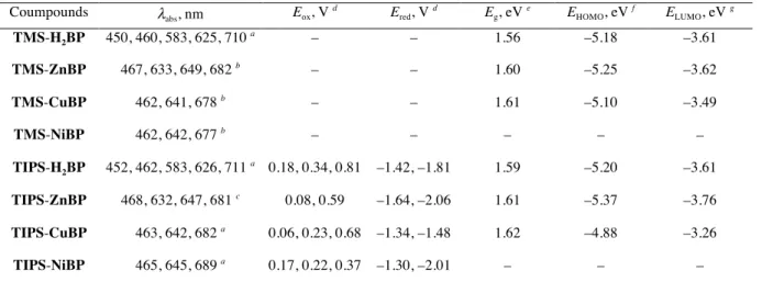
(23) Table 1. Optical and electrochemical properties Coumpounds. λabs, nm. Eox, V d. Ered, V d. Eg, eV e. EHOMO, eV f. ELUMO, eV g. TMS-H2BP. 450, 460, 583, 625, 710 a. –. –. 1.56. –5.18. –3.61. TMS-ZnBP. 467, 633, 649, 682 b. –. –. 1.60. –5.25. –3.62. TMS-CuBP. 462, 641, 678 b. –. –. 1.61. –5.10. –3.49. TMS-NiBP. 462, 642, 677 b. –. –. –. –. –. –1.42, –1.81. 1.59. –5.20. –3.61. TIPS-H2BP. a. 452, 462, 583, 626, 711 a 0.18, 0.34, 0.81. TIPS-ZnBP. 468, 632, 647, 681 c. 0.08, 0.59. –1.64, –2.06. 1.61. –5.37. –3.76. TIPS-CuBP. 463, 642, 682 a. 0.06, 0.23, 0.68. –1.34, –1.48. 1.62. –4.88. –3.26. TIPS-NiBP. 465, 645, 689 a. 0.17, 0.22, 0.37. –1.30, –2.01. –. –. –. in CH2Cl2, b in DMF,. c. in THF,. d. Potential values were measured by DPV in CH2Cl2 for TIPS-H2BP, in benzonitrile for TIPS-. ZnBP, TIPS-CuBP and TIPS-NiBP with 0.1 M n-Bu4NPF6. The ferrocene/ferrocenium cation redox couple was used as the internal standard. Scan rate = 100 mV.s–1. [sample] = 0.5 mM. Working electrode: glassy carbon. Counter electrode: Pt wire. Reference electrode: Ag/AgNO3. g. e. Determined by optical gaps from the absorption onsets in the films.. spectroscopy in air. ELUMO = EHOMO + Eg. f. Determined by photoelectron.
(24) Table 2. OTFT characteristics of TMS- and TIPS-BPs. Compounds TMS-H2BP. µFET, cm2.V–1.s–1. Ion / Ioff. 0.11. Vth, V. 2.4 × 10. 6. 8.0 × 10. 1. 19.4. 9.4 × 10. 4. –11.9. –12.3. TMS-ZnBP. 5.56 × 10. –5. TMS-CuBP. 4.49 × 10. –4. TIPS-H2BP. 4.36 × 10⁻⁵. 4.3 × 10⁴. –17.8. TIPS-ZnBP. 1.11 × 10. –5. 6.6 × 10. 3. 1.2. TIPS-CuBP. 5.61 × 10. –3. 1.9 × 10. 4. –12.2.
(25) Table 3. Device performances of TMS- and TIPS-BP-based OSCs p-type materials. Temperature, ºC. JSC, mA.cm–2. VOC, V. FF. PCE, %. TMS-H2BP. 160. 2.46. 0.48. 0.28. 0.33. 180. 5.70. 0.48. 0.40. 1.09. 200. 3.53. 0.47. 0.28. 0.47. 160. 6.79. 0.45. 0.37. 1.13. 180. 7.81. 0.46. 0.41. 1.49. 200. 7.86. 0.47. 0.39. 1.44. 160. 4.51. 0.43. 0.38. 0.72. 180. 1.83. 0.43. 0.18. 0.14. 200. 1.49. 0.42. 0.30. 0.19. 160. 3.06. 0.66. 0.29. 0.57. 180. 5.22. 0.61. 0.32. 1.02. 200. 1.43. 0.54. 0.24. 0.19. 160. 2.12. 0.68. 0.30. 0.44. 180. 5.03. 0.61. 0.37. 1.13. 200. 4.29. 0.64. 0.36. 0.99. 160. 3.85. 0.65. 0.34. 0.86. 180. 3.22. 0.37. 0.28. 0.33. 200. 3.64. 0.42. 0.28. 0.42. TMS-ZnBP. TMS-CuBP. TIPS-H2BP. TIPS-ZnBP. TIPS-CuBP.
(26)
図
+7

関連したドキュメント
The edges terminating in a correspond to the generators, i.e., the south-west cor- ners of the respective Ferrers diagram, whereas the edges originating in a correspond to the
H ernández , Positive and free boundary solutions to singular nonlinear elliptic problems with absorption; An overview and open problems, in: Proceedings of the Variational
Keywords: Convex order ; Fréchet distribution ; Median ; Mittag-Leffler distribution ; Mittag- Leffler function ; Stable distribution ; Stochastic order.. AMS MSC 2010: Primary 60E05
In [9], it was shown that under diffusive scaling, the random set of coalescing random walk paths with one walker starting from every point on the space-time lattice Z × Z converges
In Section 3, we show that the clique- width is unbounded in any superfactorial class of graphs, and in Section 4, we prove that the clique-width is bounded in any hereditary
Inside this class, we identify a new subclass of Liouvillian integrable systems, under suitable conditions such Liouvillian integrable systems can have at most one limit cycle, and
Shen, “A note on the existence and uniqueness of mild solutions to neutral stochastic partial functional differential equations with non-Lipschitz coefficients,” Computers
We see that simple ordered graphs without isolated vertices, with the ordered subgraph relation and with size being measured by the number of edges, form a binary class of
