IRUCAA@TDC : Evaluation of the implantation position of mini-screws for orthodontic treatment in the maxillary molar area by a micro CT
9
0
0
全文
(2) Bull. Tokyo dent. Coll., Vol. 45, No. 3, pp. 165⬃172, August 2004. 165. Original Article. EVALUATION OF THE IMPLANTATION POSITION OF MINI-SCREWS FOR ORTHODONTIC TREATMENT IN THE MAXILLARY MOLAR AREA BY A MICRO CT TAKENOBU ISHII, KUNIHIKO NOJIMA, YASUSHI NISHII, TAKASHI TAKAKI* and HIDEHARU YAMAGUCHI Department of Orthodontics, Tokyo Dental College, 1-2-2 Masago, Mihama-ku, Chiba 261-8502, Japan * First Department of Oral and Maxillofacial Surgery, Tokyo Dental College, 1-2-2 Masago, Mihama-ku, Chiba 261-8502, Japan. Received 20 October, 2004/Accepted for Publication 1 December, 2004. Abstract The interalveolar septum between the upper first molar and the second premolar of the separated human maxillary bone was three-dimensionally observed by micro CT to evaluate the appropriate mini-screw type implant placement position by considering the relationship between the tooth roots and the maxillary sinus. After taking micro CTs of 5 human maxillary bones, horizontally sectioned images of the interalveolar septum area 2, 4, 6, 8, 10, and 12 mm deep from the crest of the alveolar ridge were reconstructed by three-dimensional reconstruction software. The bucco-lingual and mesio-distal lengths and area in each sectioned interalveolar septum were measured using digital image measurement software. Using the results, the interalveolar septum area between the upper first molar and the second premolar approximately 6–8 mm deep from the alveolar crest in the tooth root apical direction was determined to be the safest position for mini-screw implantation. Furthermore, lateral implantation from the palatal side was deduced to be the safest approach. Key words:. Micro-CT — Mini-screw type implant — Implantation position — Orthodontic treatment — Maxillary molar area. INTRODUCTION In recent years, a new treatment mechanism using implants for orthodontic treatment has been developed and applied to clinical orthodontic treatment. This technique has enabled tooth movement that was impossible with conventional orthodontic treatment, and further developments. are expected. Although dental implant type7,18,19,24), mini-plate type9,15,22,23), and miniscrew type3–5,10–14,16,17) implants have all been used for orthodontic treatment, the miniscrew type implants are widely used in clinical cases, because of their easy implantation technique with comparatively light tissue invasion. Since Creekmore and Eklund4) clinically used mini-screw type implants below anterior. 165.
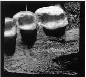
(3) 166. T. ISHII et al.. nasal spine for intrusion of the maxillary anterior teeth in 1983, there have been many reports of their clinical application to the hard palate, maxillary molar area, maxillary tuberosity, mandibular retromolar torus, and mental region3,10,12,16,17). Generally, mini-screw type implants used as a maxillary molar anchorage unit have been placed in the interalveolar septum between the upper first molar and second premolar from the buccal side to obtain mechanical treatment effects and secure a safe surgical field, frequently based on the clinician’s clinical experience10,11,13,14,16). However, because buccal implantation may cause problems such as injury to the tooth roots and perforation of the maxillary sinus11), detailed anatomical evaluation is necessary. Although the implantation position of the dental implant type has been evaluated using CT for general clinical treatment2), there have been no basic studies of the placement position of the mini-screw type implants in the maxillary molar area. In this study, the interalveolar septum area between the upper first molar and the second premolar in the separated human maxillary bone was three-dimensionally observed by micro CT, and the appropriate mini-screw type implant placement position was evaluated, specifically considering the relationship between the tooth roots and the maxillary sinus.. MATERIALS AND METHODS 1. Study specimens From the separated human maxillary bones with permanent dentition preserved in the Department of Anatomy, Tokyo Dental College, five specimens satisfying the following conditions were selected. Their genders and ages were randomly selected. 1) The growth period finished. 2) No bone destruction due to periodontal disease was observed. 3) No apical lesions were detected by micro CT. To eliminate noise, any soft tissue in the. Fig. 1 Three-dimensional images of the area between the upper first molar and the second premolar. specimens was removed before taking the CT. 2. CT conditions Each CT was taken using a micro CT (KSM755, Kashimura Co.) under the following conditions; tube voltage: 55.0 kV, tube current: 100 A, magnification: 1.5 times, and slice thickness: approximately 49.5 m. The occlusal plane of the specimen was set perpendicular to the rotation axis of the stage. After placing the interalveolar septum between the upper first molar and second premolar in the center of the CT-taking area, the specimens were fixed with utility wax. 3. Measurements before treatment By the back projection method, approximately 600 sliced images were obtained from the raw data taken. Three-dimensional images of the area between the upper first molar and second premolar were constructed using three-dimensional construction software (Vox Blast) (Fig. 1). Thereafter, by the volume rendering method, images of the interalveolar septum area between the upper first molar and second premolar horizontally sectioned parallel to the occlusal plane 2, 4, 6, 8, 10, and 12 mm deep from the crest of the alveolar ridge to the tooth root apical direction were reconstructed (Fig. 2)..
(4) 167. THE IMPLANTATION POSITION OF MINI-SCREWS. 2 mm. 4 mm. 6 mm. 8 mm. 10 mm. 12 mm. Fig. 2 Images of the interalveolar septum area between the upper first molar and the second premolar sectioned 2, 4, 6, 8, 10, and 12 mm deep. (a: The root of the second premolar, b: The mesio-buccal root of the first molar, c: The palatal root of the first molar). Fig. 3 Measurement of the bucco-lingual length The mean, minimum and maximum lengths of the line connecting the buccal bone surface and palatal bone surface without contact with the tooth roots were measured. When measurements from the buccal side differed from those from the lingual side due to the morphology and position of the tooth roots, measurements were performed from both sides.. 4. Measurement methods Automatic tracing of the horizontally sectioned images was performed based on differences in the CT values by digital image measurement software (Image Pro-Plus 4.5). This software is designed to automatically measure the mean, minimum, and maximum distances between two lines. Then, in the horizontally sectioned interalveolar septum area between the upper first molar and second premolar 2, 4, 6, 8, 10, and 12 mm deep from the alveolar crest, the following measurements were made. When the maxillary sinus appeared, they became impossible. 1) The bucco-lingual length of the interalveolar septum The minimum and maximum lengths of. Fig. 4 Measurements of the mesio-distal length The tangent was bucco-palatally drawn to each tooth root, and after removing the undercut area from the measurement area, the mean, minimum and maximum lengths were measured. When the upper first molars had furcating palatal and buccal roots, the distance between the tooth root of the second premolars and the palatal root of the first molars ( ) and that between the tooth root of the second premolars and the mesio-buccal root of the first molars ( ) were measured.. Fig. 5 Measurement of the area of the interalveolar septum The area of the region surrounded by the bucco-lingual length and the mesio-distal length was measured.. the line connecting the buccal bone surface and palatal bone surface without contact with the tooth roots were measured as the minimum distance and maximum distance,.
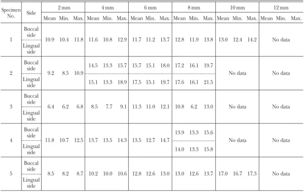
(5) 168. T. ISHII et al.. Table 1 Measurement of the bucco-lingual length of the interalveolar septum in 5 separated human maxillary bones (mm) Specimen No.. 1. Side Buccal side. 2 mm. 4 mm. 6 mm. 8 mm. 10 mm. 12 mm. Mean Min. Max. Mean Min. Max. Mean Min. Max. Mean Min. Max. Mean Min. Max. Mean Min. Max.. 10.9 10.4 11.8 11.6 10.8 12.9 11.7 11.2 13.7 12.8 11.9 13.8 13.0 12.4 14.2. No data. Lingual side. 2. Buccal side. 14.5 13.3 15.7 15.7 15.1 18.0 17.2 16.1 19.7 9.2. 8.5 10.9. Lingual side. 3. Buccal side. No data. No data. No data. No data. No data. No data. 15.1 13.3 18.9 17.5 15.1 19.7 17.6 16.1 21.5. 6.4. 6.2. 6.8. 8.5. 7.7. 9.1 11.3 11.0 12.1 10.8. 6.2. 13.0. Lingual side. 4. Buccal side. 13.9 13.3 15.6 11.8 10.7 12.5 13.7 13.5 14.3 13.5 12.7 14.7. Lingual side. 5. Buccal side. 14.0 13.3 15.8. 8.5. 8.2. 8.7 10.2 10.0 10.6 12.8 12.6 13.0 13.0 12.6 13.7 17.0 16.7 17.3. No data. Lingual side. respectively, and the mean length was calculated as the mean distance. When measurements from the buccal side differed from those from the lingual side due to the morphology and position of the tooth roots, measurements were performed from both sides (Fig. 3). 2) The mesio-distal length of the interalveolar septum The tangent was bucco-palatally drawn to each tooth root, and, after removing the undercut area from the measurement area, the minimum and maximum lengths in the area were measured. Then the mean length was calculated. When the upper first molar had furcating palatal and buccal roots, the distance between the tooth root of the second premolar and the palatal root of the first molar and that between the tooth root of the second premolar and the mesio-buccal root of the first molar were measured (Fig. 4). 3) The area of the interalveolar septum region The area of the region surrounded by the. bucco-lingual length and the mesio-distal length was measured (Fig. 5).. RESULTS Measurements of the bucco-lingual length of the interalveolar septum are shown in Table 1. The bucco-lingual length increased with the depth from the crest of the alveolar ridge in the tooth root apical direction. Although differences were noted among the specimens, the increase rate decreased between the horizontally sectioned 6-mm deep area and 8-mm deep area. The minimum value was 6.2 mm in the horizontally sectioned 2-mm deep area, and the maximum value was 21.5 mm in the 8-mm deep area. In the horizontally sectioned 10-mm deep area, measurement was impossible in 3 of the 5 specimens due to the appearance of the maxillary sinus in the measurement area. In the 12-mm deep area, the maxillary sinus appeared in all 5 specimens..
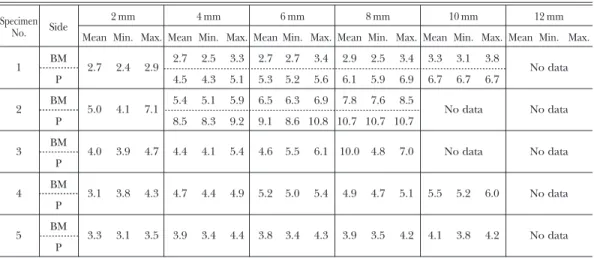
(6) 169. THE IMPLANTATION POSITION OF MINI-SCREWS. Table 2 Measurement of the mesio-distal length of the interalveolar septum in 5 separated human maxillary bones (mm) Specimen No. 1. Side BM. 2 mm. 4 mm. BM. 2.7. 2.4. 2.9. 5.0. 4.1. 7.1. P 3. BM. 8 mm. 10 mm. 12 mm. Mean Min. Max. Mean Min. Max. Mean Min. Max. Mean Min. Max. Mean Min. Max. Mean Min. Max.. P 2. 6 mm. 2.7. 2.5. 3.3. 2.7. 2.7. 3.4. 2.9. 2.5. 3.4. 3.3. 3.1. 3.8. 4.5. 4.3. 5.1. 5.3. 5.2. 5.6. 6.1. 5.9. 6.9. 6.7. 6.7. 6.7. 5.4. 5.1. 5.9. 6.5. 6.3. 6.9. 7.8. 7.6. 8.5. 8.5. 8.3. 9.2. 9.1. 8.6 10.8 10.7 10.7 10.7. No data. No data. No data. No data. No data. 4.0. 3.9. 4.7. 4.4. 4.1. 5.4. 4.6. 5.5. 6.1 10.0 4.8. 7.0. 3.1. 3.8. 4.3. 4.7. 4.4. 4.9. 5.2. 5.0. 5.4. 4.9. 4.7. 5.1. 5.5. 5.2. 6.0. No data. 3.3. 3.1. 3.5. 3.9. 3.4. 4.4. 3.8. 3.4. 4.3. 3.9. 3.5. 4.2. 4.1. 3.8. 4.2. No data. P 4. BM P. 5. BM P. BM: Mesio-buccal root of the first molar, P: Palatal root of the first molar. Table 3 Measurement of the area of the interalveolar septum in 5 separated human maxillary bones (mm2) Specimen No.. 2 mm. 4 mm. 6 mm. 8 mm. 10 mm. 12 mm. 1. 33.2. 41.0. 45.1. 51.1. 57.5. No data. 2. 52.6. 109.2. 123.5. 160.5. No data. No data. 3. 38.1. 42.3. 61.0. 71.4. No data. No data. 4. 48.7. 64.9. 71.9. 81.8. No data. No data. 5. 28.0. 38.3. 49.4. 48.1. 55.7. No data. The mesio-distal length of the interalveolar septum is shown in Table 2. Although the upper first molar has buccal and palatal roots, the mesio-distal length between the tooth root of the second premolar and the palatal root of the first molar was longer than that between the tooth root of the second premolar and the mesio-buccal root of the first molar, and the former value was approximately twice as long as the latter value in specimen 1 in this study. The proportion of the former against the latter increased with the depth in the tooth root apical direction. Although the maximum difference between the maximum and minimum distance was 2.2 mm, no remarkable differences were noted in almost all of the specimens. In the. horizontally sectioned 10-mm deep area, measurement was impossible in 2 of the 5 specimens due to the appearance of the maxillary sinus. In the 12-mm deep area, the maxillary sinus appeared in the measurement area in all specimens. Measurements of the area of the interalveolar septum region are shown in Table 3. The minimum value was 28 mm2 in the horizontally sectioned 2-mm deep area, and the maximum value was 160.5 mm2 in the 8-mm deep area. Therefore, the area increased with the depth from the crest of the alveolar ridge in the tooth root apical direction. It is therefore evident that safety increases with the depth in the tooth root apical direction. However, in the horizontally sectioned 10-mm.
(7) 170. T. ISHII et al.. deep area, measurement was impossible in 3 of the 5 specimens due to the appearance of the maxillary sinus. In the 12-mm deep area, the maxillary sinus appeared in the measurement area in all specimens.. DISCUSSION The resolution of micro CT is higher than those of CT and pQCT apparatus for general clinical treatment, and non-destructive observation and quantitative analysis of image data are possible by micro CT 20). After examining the accuracy of micro CT, Shibuya et al. reported that measurements of images obtained by micro CT were almost in accordance with the actually measured specimen length and width and the calculated volume and surface area21). Previous reports have analyzed cancellous bone around dental implants using non-destructive and highresolution micro CT, and micro CT has been applied to dental studies1,8). Therefore, micro CT, by which arbitrarily sectioned highresolution images can be non-destructively obtained and with which measurement with high accuracy is possible, was chosen for this study. The implantation position of mini-screw type implants is determined by methods such as implantation after calculating the vertical distance between the occlusal plane and the implantation position using lateral cephalography and then producing resin templates on models13), inclined implantation to avoid injury to the tooth roots, consideration of the alveolar bone surface under the contact point14), implantation after taking dental Xrays with the acrylic surgical index attached to the teeth16), implantation after producing stents on models and then taking CT11), and implantation in an area with anatomically comparatively thick cortical bone without nerves or vessels3). Although these methods can be indexes for evaluating the appropriate implantation position of mini-screw type implants, tooth root position in the alveolar bone and the three-dimensional position of. the maxillary sinus are not considered. Therefore, we believe that the number of accidents such as injury to the tooth roots will increase with the wider use of implant anchors, because the implantation of mini-screw type implants continues to be performed based on each clinician’s clinical experience. Our observations show that both the buccolingual length of the interalveolar septum between the upper first molar and second premolar and the mesio-distal length between the upper first molar tooth roots and second premolar tooth roots increased from the crest of the alveolar ridge in the tooth root apical direction. The area in which implantation is possible also increases in the tooth root apical direction. However, the maxillary sinus appeared in an area more than 10 mm deep from the alveolar crest in the tooth root apical direction in some specimens, which was inappropriate for implantation. The diameter of the mini-screw type implants currently used for clinical cases is 1.2–1.4 mm, and the length is 4–8 mm. When implantation parallel to the occlusal surface is assumed, our results suggest that the area 6–8 mm deep from the alveolar crest, which has the maximum measurements in the bucco-lingual length, is the safest position for lateral implantation. Therefore, our results indicate that the area approximately 6–8 mm deep from the crest of the alveolar ridge in the tooth root apical direction is the safest and most secure position for the implantation of mini-screw type implants. Furthermore, our data also indicate that the safe implantation area widens by laterally placing the implants from the palatal side compared to that by placing from the buccal side. Although it has been reported that thick cortical bone area is optimal for implantation3), there are no differences in the thickness of the cortical bone between the buccal and lingual side in the maxillary alveolar area6). However, because the maximum bucco-lingual length is shorter than the length of the mini-screw type implants in some cases, it is necessary to select the length of the mini-screw type implants considering variations in the bucco-lingual length among.
(8) THE IMPLANTATION POSITION OF MINI-SCREWS. patients. Therefore, the degree of safety during implantation is increased by establishing markers such as stents and reconfirming the implantation position on X-rays. Furthermore, our results suggest that the occurrence of problems during the placement of miniscrew type implants in the maxillary molar area can be prevented by these methods. Not only an increase in the number of specimens but also an evaluation of other areas used for orthodontic treatment, in which the use of implant anchors is rapidly increasing, is needed to increase to utility of our data.. CONCLUSION The placement of mini-screw type implants in the interalveolar septum area between the upper first molar and the second premolar approximately 6–8 mm deep from the alveolar crest, not from the buccal side, but from the palatal side, was determined to be the safest technique.. ACKNOWLEDGEMENTS The authors extend their sincere gratitude to the members of the Department of Anatomy, Tokyo Dental College, for their kind advice.. REFERENCES 1) Akahori, Y. and Adachi, Y. (2001). Observation of internal structure of the canine mandible by microcomputed tomography: A morphometric evaluation of the cancellous bone around titanium implants. Shikwa Gakuho 101, 457–470. (in Japanese) 2) Bernhart, T., Vollgruber, A., Gahleitner, A., Dortbudak, O. and Haas, R. (2000). Alternative to the median region of the palate for placement of an orthodontic implant. Clin Oral Impl Res 11, 595–601. 3) Costa, A., Raffaini, M. and Melsen, B. (1998).. 4) 5) 6). 7) 8). 9) 10) 11) 12). 13). 14) 15) 16) 17). 18). 19). 171. Miniscrews as orthodontic anchorage: A preliminary report. Int J Adult Orthod Orthognath Surg 13, 201–209. Creekmore, T.D. and Eklund, M.K. (1983). The possibility of skeletal anchorage. J Clin Orthod 17, 266–269. Giancotti, A., Muzzi, F., Santini, F. and Arcuri, C. (2003). Miniscrew treatment of ectopic mandibular molar. J Clin Orthod 37, 380–383. Hara, T. and Ide, Y. (2001). Interstructural changes of the jaws caused by tooth loss — Observation of trabecular bone structure by CT. Shikaigeppou 596, 29-35. (in Japanese) Herrero, D.B. (1998). Implants as anchorage in orthodontics: A clinical case report. J Oral Implantol 24, 5–10. Ito, M., Hayashi, K., Matuda, H., Ikeda, S. and Turukami, H. (1999). Micro-computed tomography for three-dimensional analysis of trabecular bone. J Jpn Soc Bone Morphom 9, 1–11. Jenner, J.D. and Fitzpatrick, B.N. (1985). Skeletal anchorage utilizing bone plates. Aust Orthod J 9, 231–233. Kanomi, R. (1997). Mini-implant for orthodontic anchorage. J Clin Orthod 31, 763–767. Kanomi, R., Sone, Y. and Inoue, M. (2002). Orthodontic treatment utilizing K-1 system. Dental Outlook 99, 671–677. (in Japanese) Kyung, H.M., Park, H.S., Bae, S.M., Sung, J.H. and Kim, I.B. (2003). Development of orthodontic micro-implant for intraoral anchorage. J Clin Orthod 37, 321–328. Kyung, S.H., Choi, J.H. and Park, Y.C. (2003). Miniscrew anchorage used to protect lower second molar into first molar extraction sites. J Clin Orthod 37, 575–579. Kyung, S.H., Hong, S.G. and Park, Y.G. (2003). Distalization of maxillary molar with a mid palatal miniscrew. J Clin Orthod 37, 22–26. Likow, L.I. (1969). The endosseous blade implant and its use in orthodontics. Int J Orthodontics 7, 149–154. Maino, B.G., Bednar, J. Pagin, P. and Mura, P. (2003). The spider screw for skeletal anchorage. J Clin Orthod 37, 90–97. Paik, C., Woo, Y.J. and Boyd, R. (2003). Treatment of an adult patient with vertical maxillary excess using miniscrew fixation. J Clin Orthod 37, 423–428. Roberts, W.E., Marshall, K.J. and Mozsary, P.G. (1990). Ridged endosseous implant utilized as anchorage to protract molar and close an atrophic extraction site. Angle Orthod 60, 135– 152. Saitou, S., Morohashi, T. and Shibasaki, Y. (2001). Usefulness of titanium implants for orthodontics (Part 1). Journal of Orthodontic.
(9) 172. T. ISHII et al.. Practice 17, 23–40. (in Japanese) 20) Shibuya, E., Hara, T. and Ide, Y. (2001). An internal structure in mental region of human jaw bone using micro-CT. J Jpn Soc Bone Morphom 11, 37–47. (in Japanese) 21) Shibuya, E., Matsubayashi, T. and Shida, T. (2000). Experimental study for the accuracy Micro-CT apparatus. Shikwa Gakuho 100, 1221–1226. (in Japanese) 22) Sugawara, J., Nagasaka, H., Umemori, M., Takahashi, I., Miyota, H., Daimaruya, T., Kawamura, H. and Mitani, H. (2002). Skeletal anchorage systems and their practical use. Dental Outlook 99, 397–406. (in Japanese) 23) Umemori, M., Sugawara, J., Mitani, H., Nagasaka, H. and Kawamura, H. (1998).. Skeletal anchorage system for open-bite correction. Am J Orthod Dentofacial Orthop 115, 166–174. 24) Wehrbein, H., Merz, B. and Diedrich, P. (1999). Palatal bone support for orthodontic implant anchorage — a clinical and radiological study. Eur J Orthod 21, 65–70. Reprint requests to: Dr. Takenobu Ishii Department of Orthodontics, Tokyo Dental College, 1-2-2 Masago, Mihama-ku, Chiba 261-8502, Japan.
(10)
図

関連したドキュメント
Then the change of variables, or area formula holds for f provided removing from counting into the multiplicity function the set where f is not approximately H¨ older continuous1.
It is suggested by our method that most of the quadratic algebras for all St¨ ackel equivalence classes of 3D second order quantum superintegrable systems on conformally flat
In Section 3 the extended Rapcs´ ak system with curvature condition is considered in the n-dimensional generic case, when the eigenvalues of the Jacobi curvature tensor Φ are
This paper develops a recursion formula for the conditional moments of the area under the absolute value of Brownian bridge given the local time at 0.. The method of power series
We present sufficient conditions for the existence of solutions to Neu- mann and periodic boundary-value problems for some class of quasilinear ordinary differential equations.. We
In Section 13, we discuss flagged Schur polynomials, vexillary and dominant permutations, and give a simple formula for the polynomials D w , for 312-avoiding permutations.. In
Analogs of this theorem were proved by Roitberg for nonregular elliptic boundary- value problems and for general elliptic systems of differential equations, the mod- ified scale of
Then it follows immediately from a suitable version of “Hensel’s Lemma” [cf., e.g., the argument of [4], Lemma 2.1] that S may be obtained, as the notation suggests, as the m A
