Synthesis and Properties of Partially
Fluorinated Aromatic Ionomers
A Doctoral Thesis
Presented to the
Integrated Graduate School of
Medicine, Engineering, and Agricultural Sciences
University of Yamanashi
March 2019
Jinju Ahn
Contents
Chapter 1. Introduction
1.1.
Proton exchange membranes for application of PEMFC ... 1
1.2.
Perfluorosulfonic acid membranes and ionomers ... 2
1.3.
Sulfonated aromatic membranes ... 2
1.3.1.
Proton transport mechanism... 5
1.3.2.
The design for property improvement ... 7
1.3.3.
Control of IEC of polymer ... 7
1.3.3.1.
Control of acidity and concentration of sulfonic acid groups ... 7
1.3.3.2.
Well-developed phase separation between hydrophilic and hydrophobic parts
as block-polymers ... 9
1.4.
The objective of the research ... 11
References ... 12
Chapter 2. Sulfonated terpolymers containing alkylene and perfluoroalkylene
groups: effect of aliphatic groups on membrane properties
2.1.
Introduction ... 14
2.2.
Measurements ... 15
2.3.
Experimental ... 17
2.3.1.
Materials ... 17
2.3.2.
Polymerization of terpolymer (SPA-A and B) ... 17
2.3.3.
Membrane preparation and Acidification ... 18
2.4.
Results and discussion ... 18
2.4.1.
Synthesis of Terpolymers (SPA) ... 18
2.4.2.
Morphology ... 21
2.4.3.
Proton conductivity and water uptake ... 22
2.4.4.
Mechanical properties... 25
2.4.5.
Fuel Cell Performance ... 27
2.5.
Conclusions ... 34
Chapter 3. Sulfonated aromatic polymers containing hexafluoroisopropylidene
groups
3.1
Introduction ... 36
3.1.
Measurements ... 36
3.2.
Experimental ... 38
3.2.1.
Materials ... 38
3.2.2.
Polymerization ... 38
3.2.3.
Preparation of catalyst-coated membrane (CCM) ... 39
3.3.
Results and discussion ... 39
3.3.1.
Synthesis of SBAF copolymers and membranes ... 39
3.3.2.
Morphology ... 42
3.3.3.
Proton conductivity and Water uptake ... 43
3.3.4.
Mechanical properties... 46
3.3.5.
Oxidative stability in Fenton’s reagent ... 49
3.3.6.
Gas permeability ... 52
3.3.7.
Fuel cell performance ... 53
3.4.
Conclusions ... 58
References ... 58
Chapter 4. The simple design of novel partially fluorinated polymers containing
trifluoromethyl (-CF
3-) group on sulfonated polyphenylene
4.1.
Introduction ... 59
4.2.
Experimental ... 59
4.2.1.
Measurements ... 59
4.2.2.
Materials ... 60
4.2.3.
Synthesis of homo-, co- and ter-polymers with dichlorobenzotrifluoride ... 61
4.2.4.
Synthesis of 4,4’-dichloro-2,2’-bis(trifluoromethyl)biphenyl ... 61
4.2.5.
Co-polymerization
(STF-BP)
with
4,4’-dichloro-2,2’-bis(trifluoromethyl)biphenyl ... 61
4.2.6.
Membrane preparation ... 62
4.3.
Results and discussion ... 62
4.3.2.
Co-polymerization
with
synthesized
4,4’-dichloro-2,2’-bis(trifluoromethyl)biphenyl (STF-BP) ... 64
4.3.3.
Proton conductivity and Water uptake ... 66
4.3.4.
Mechanical properties... 67
4.4.
Conclusions ... 68
References ... 69
Chapter 5. Conclusions and Future proposals
List of publications ... 72
Meeting abstracts ... 72
1
Chapter 1. Introduction
1.1. Proton exchange membranes for application of PEMFC
Renewable energy sources like fuel cells have been promising to play a key role in the replacement of fossil fuels due to global energy concerns. Fuel cells efficiently convert chemical energy to electrical energy through an eco-friendly system. Fuel cells can be divided into five kinds according to the type of electrolyte: AFC (alkaline fuel cell), PEMFC (proton exchange membrane fuel cell), PAFC (phosphoric acid fuel cell), MCFC (molten carbonate fuel cell), and SOFC (solid oxide fuel cell). Among these, PEMFCs have been considered for application in transport and stationary and portable power generation. [1-5]
PEMFCs consist of anode, membrane, and cathode, as shown in Figure 1. The basic principle of a PEMFC is the reverse reaction of water electrolysis. At the anode, hydrogen gas generates electrons and protons. Protons are conducted from anode to cathode through the membrane; then, at the cathode, these protons, as well as the electrons, react with oxygen. The membrane is the fundamental component for PEMFC operation, because it supports ion transport from anode to cathode and prevents direct mixing of hydrogen and oxygen as a separator between the electrodes. The membranes are required to possess such qualities as high proton conductivity and high chemical and thermal stability.
2
1.2. Perfluorosulfonic acid membranes and ionomers
The most famous and widely used commercial polymeric materials are the perfluorosulfonic acid ionomers Nafion, made by Dupont, and Flemion, made by Asahi Glass, as described in Figure 2. The perfluorosulfonic acid membrane is prepared by the radical copolymerization of tetrafluoroethylene (TFE) (the monomer in Teflon) and a derivative of a perfluoro (alkyl vinyl ether) with sulfonyl acid fluoride. The Teflon backbone of perfluorosulfonic acid ionomers contributes high chemical and mechanical stability and superior high proton conductivity due to the presence of superacid groups. However, the complications of the manufacturing process make it expensive, and the low thermal stability (< 100℃) leads to a limited narrow service temperature range. In addition, its high gas permeability results in low durability for long-term fuel cell performance. [6 - 9] For the commercialization of PEMFCs, alternative materials need to be developed and put forward for consideration.
Figure 2. The chemical structure of perfluoro sulfonic acid ionomers
1.3. Sulfonated aromatic membranes
Many researchers have developed various alternative membranes to overcome the drawbacks of Nafion. The most attractive materials with the highest potential are sulfonated aromatic polymers, which are inexpensive, due to the simplicity of their synthetic process, and have high thermal stability and low gas permeability. There are several kinds of sulfonated aromatic polymers [10-19], the most prominent of which are SPEs (sulfonated poly (arylene ether)s); SPESs (sulfonated poly (ether sulfone)s) and SPEEKs (sulfonated poly (ether ether ketone)s), SPPs (sulfonated poly (p-phenylene)s), and SPIs (sulfonated polyimides).
3
in Figure 3. These materials have been prepared by direct polymerization between the OH-terminated and halide-terminated (F and Cl) monomers. Many research groups have reported effective structures and investigated their membrane properties. The SPEs membranes can be prepared as structurally random or as block polymers with high molecular weight and high proton conductivity. However, when compared with the Nafion membrane, they still have significantly lower proton conductivity under low humidity conditions (< 50 % RH), even though it has higher water uptake due to higher ion exchange capacity (IEC). Moreover, the SPE membranes have insufficient performance during cell operation, due to lower oxidative and mechanical stability.
Figure 3. Chemical structures of aromatic materials
The SPP (sulfonated poly(p-phenylene)s) membranes have been considered to be important due to expected higher oxidative stability. As opposed to SPE membranes, SPPs consist of benzene rings without heteroatom groups (ether, sulfone, ketone, and so on) which are chemically vulnerable under fuel cell operation conditions. In general, the SPP membranes are very stiff, with insufficient elongation, due to the rigid polymer backbone, containing para-linked benzene rings. Generally, the poly(p-phenylene)s are highly crystalline, rigid rod polymers that are difficult to handle due to their very low flexibility and low solubility in organic solvents, which impose limits on the formation of membranes for applications and property testing. Several researchers have suggested ways to overcome these kinds of drawbacks through the use of modified poly(p-phenylene)s.
McGrath and coworkers reported soluble sulfonated poly(p-phenylene) derivatives [20], which were prepared by Ni-catalyzed coupling polymerization with aryl-substituted 2,5-dichlorobenzophenone, as shown in Figure 4. Even though it is possible to prepare homo- and co-polymer membranes, the obtained membranes are very brittle. However, non-sulfonated co-polymers showed high thermal stability, with only 5% weight loss at temperatures over 480℃. This polymer was blended or composited with fiberglass fabric and PEPO (poly(arylene ether phenyl phosphine oxide)). The proton conductivity of those polymers exhibited 90-110 mS cm-1, measured on a polymer composite made from fiberglass fabric and resin (40/60 w/w).
4
Figure 4. Chemical structures of sulfonated poly(p-phenylene) derivatives with 2,5-dichlorobenzophenone and PEPO
Holdcroft and coworkers designed and prepared phenylated polyphenylene ionomers [21, 22] by Diel-Alder polymerization reaction, as shown in Figure 5. Sulfophenylated polyphenylenes are obtained by incorporation of spacer units, biphenyl (sPPP-H+) and naphthyl (sPPN-H+), in the polymer backbone. The sPPP-H+ and sPPN-H+ membranes have excellent tensile strength, Young’s modulus (59.6 MPa for sPPB-H+ and 1331Mpa for sPPN-H+, respectively). As expected, they had low elongation at break (17.5%) under dry conditions. Furthermore, the high durability of the membrane was confirmed under accelerated stress testing, maintaining high conductivity even after 400 hours due to its high oxidative stability.
5
In our laboratory, we developed and synthesized a simpler version of sulfonated polyphenylene (SPP-QP) [23] composed only of phenylene rings and sulfonic acid groups, as described in Figure 6. Although the SPP-QP membranes consisted of only benzene rings, m- and p-phenylene and sulfonated monomer, by carefully optimizing the m-/p- composition and ion exchange capacity (IEC), we proved that sulfonated polyphenylene with a very simple polymer structure provided flexible and bendable thin membranes with high proton conductivity and superior oxidative stability in comparison with SPK membranes.
Figure 6. Chemical structures of sulfonated poly(phenylene) (SPP-QP) composed only of phenylene rings and sulfonic acid groups. [23]
Recently developed sulfonated aromatic materials have been researched and have achieved much higher performance than before. However, we still need to overcome several deficiencies of the membrane properties like proton conductivity, particularly under low humidity conditions, oxidative stability, mechanical stability with reasonable hydrated dimensional stability and compatibility with catalyst layers.
1.3.1. Proton transport mechanism
The major function of the membrane is proton conductivity. According to the literature, ion transport [24-26] in the membrane is generally explained by three mechanisms, Grotthus (hopping), vehicular (diffusion) and surface-mediated transport, as described in Figure 7. The vehicular mechanism is the movement of larger cations like water-solvated species (H2O2+, H9O4+, etc.). In contrast to other cations, protons may also move via structural diffusion which is referred to as the Grotthus mechanism. The bound nature of the counter anion (-SO3- in the case of sulfonic acid-base polymer electrolytes) also presents a third mode for proton transport, surface transport. In this mechanism, protons are believed to be transported between -SO3- groups located on the walls of hydrophilic channels, but this model of transport has a high activation energy. In systems with relatively high water contents, it is
6
likely that vehicular and Grotthus mechanisms predominate.
Figure 7. Schematic illustration of different modes of proton conduction in a solid polymer electrolyte where A = Grotthus, B = vehicular, and C = surface mechanisms. Adapted from [26].
As a conclusion based on the literature, we can understand that proton conductivity is strongly related to water utilization in the hydrophilic part of the polymer containing -SO3H- groups. According to that, not only higher ion exchange capacity (IEC) of the membrane but also a higher concentration of sulfonic acid groups (-SO3H) lead to both higher water uptake and higher proton conductivity. Even though high water uptake supports high proton conductivity, it also could cause excess swelling of the membrane, leading to dimensional instability. Furthermore, excess swelling of membranes usually can cause fatally low durability in wet-dry cycling during fuel cell operation. Therefore, we need to find optimized membranes offering a balance between water uptake and proton conductivity and prove that the membranes are sufficiently optimized by evaluation of the proton conductivity and mechanical stability under a range of humidity conditions.
7
1.3.2. The design for property improvement
To improve the proton conductivity, three main approaches can be considered for the synthesis: 1) control of ion exchange capacity (IEC); 2) introduction of high acidity and high concentration of sulfonic acid groups; and 3) promotion of structural block polymers for well-developed phase separation between hydrophilic and hydrophobic parts.
1.3.3. Control of IEC of polymer
To control ion exchange capacity (IEC) by synthetic methods would be an easy, simple way to improve proton conductivity. There are two ways to prepare sulfonated aromatic polymers: direct polymerization with pre-sulfonated monomers and post-sulfonation after polymerization. In general, the direct polymerization with pre-sulfonated monomers is convenient to control the IEC of a polymer by controlling the feed ratio of pre-sulfonated monomers. However, lower molecular weight of the obtained polymers occurs due to relatively lower reactivity of the sulfonated monomer. On the other hand, post-sulfonation after polymerization could provide higher molecular weight of polymers with higher reactivity of the monomers in comparison with pre-sulfonated monomers. However, the inefficient post-sulfonation reaction of polymers, with low yield (less than 60%), makes it difficult to control IEC, and the need for a second step to produce the targeted sulfonated polymer is not attractive for commercialization. Even though high water uptake supports high proton conductivity, it also could cause excess swelling of the membrane, leading to dimensional instability with the Nafion ionomer in the catalyst layer. If the IEC value of a membrane is excessively high, it could result either in significant swelling of the membrane dimensions or its dissolution in water, depending on its properties.[26, 27]
1.3.3.1. Control of acidity and concentration of sulfonic acid groups
The second approach, to control the acidity of the sulfonic acid group, for example, using a higher acidity group like a fluoroalkyl sulfonic acid or introducing a high concentration of sulfonic acid groups on the polymeric material, can be considered. According to this general approach, many researchers have suggested specific approaches, as follows.
Chulsung Bae and coworkers [28, 29] reported the effects of the acidity of sulfonic acid groups on membrane properties, especially on proton conductivity and morphology, as described in Figure 8. Three types of SEBS ionomers with different strength acidic groups, like fluoro alkylsulfonic acid, arylsulfonic acid and arylphosphonic acid, were prepared by the palladium-catalyzed Suzuki-Miyaura
8
cross reaction. The higher acidity groups like the fluoroalkyl sulfonic acid exhibited significantly higher proton conductivity than the less acidic aryl and alkyl sulfonated ionomers with higher water uptake. As expected, higher acidity of the sulfonic acid led to higher proton conductivity, although all polymers needed to be prepared by the post-sulfonation method.
Figure 8. The chemical structure of SEBS ionomers with different strength acidic groups like fluoroalkylsulfonic acid, arylsulfonic acid and arylphosphonic acid with expected effects [28].
Byungchan Bae and coworkers [30, 31] reported a high concentration of sulfonic acid groups as the hydrophilic part of multi-block SPES membranes, as shown in Figure 9. The SPES polymers obtained with higher concentrations of sulfonic acid groups have higher water uptake and higher proton conductivity, due to their well-developed phase separation between hydrophilic and hydrophobic parts in TEM images with similar IEC.
Figure 9. The chemical structure and TEM image of Block SPAES (IEC 2.8 mequiv g-1); high concentration of sulfonic acid group on hydrophilic part of multi-block SPES polymers [31]
Ueda and coworkers [32] reported locally and densely sulfonated poly(ether sulfone)s membranes, as shown in Figure 10. The polymers were synthesized by nucleophilic substitution 4, 4’ - dichlorodiphenyl sulfone with 1, 2, 4, 5 - tetrakis ( [ 1, 1’ - biphenyl ] - 2 - oxy ) - 3, 6 - bis ( 4 -
9
hydrozyphenoxy ) benzene and 2,2’- bis ( 4 -hydroxyphenyl ) hexafluoropropane, followed by sulfonation using chlorosulfonic acid. The large difference in polarity between the locally and densely sulfonated units and hydrophobic units of the polymers resulted in the formation of well-defined phase-separated structures, which enabled efficient proton conduction over a wide relative humidity range (30 - 95 %RH) at 80 °C.
Figure 10. The chemical structure of locally and densely sulfonated poly(ether sulfone)s membrane [32].
As a result, we could expect high acidity and locally and densely concentrated sulfonic acid groups in the membrane could be a helpful and effective approach to improve proton conductivity because of improved water uptake and the influence of well-developed phase separation between hydrophilic and hydrophobic moieties.
1.3.3.2. Well-developed phase separation between hydrophilic and
hydrophobic parts as block-polymers
Previously, sulfonated polymers like SPEs membranes were mainly developed as statistically random polymers. To improve proton conductivity, the chemical structure of the polymer was artificially made to produce multi-block polymers to boost the formation of wider water pathways to transport protons more effectively, similar to having a locally highly dense concentration of sulfonic acid groups on the hydrophilic part and also introducing a strongly hydrophobic part. According to this approach, many researchers have suggested specific approaches, as follows.
Na and coworkers [33] reported block sulfonated poly(ether ether ketone)s (SPEEKs) materials, prepared and characterized as described in Figure 11. The block and random SPEEK membranes were prepared and compared. Both membranes were obtained with high molecular weight and offered tough membranes. The block SPEEK membrane had higher proton conductivity (0.03 S cm-1), even though it had lower IEC (0.488 mequiv g-1) than those of a random SPEEK membrane (0.02 S cm-1) at 80℃.
10
This result is related to the larger ionic cluster size in SAXS profiles. This must be due to the influence of larger ionic cluster size on improved proton conductivity.
Figure 11. The chemical structure of block sulfonated SPEEKs [33].
Recently, our laboratory has considered that a block (statistical) chemical structure could cause higher proton conductivity due to its larger hydrophilic cluster size of phase separation that has an influence on well-connected water pathways; however, it also could make it inhomogeneous on the surface of the membrane, as described in Figure 12. According to a reference [34], both cells, the multiblock-cell and random-cell, have similar proton conductivities, but the multiblock-cell possessed lower mass activity than the random-cell, i.e., lower cell performance. Rather, this indicates that the well-developed phase separation of the block polymer is not compatible with the catalyst layer, resulting in low performance. Additionally, it could be favorable for the transport of protons with high water content in the membrane, but for the catalyst layer, a high degree of water swelling has adverse effects, like blocking the pores of the catalyst or gas diffusion layers, limiting reactant mass transport. The excessive water swelling in the membrane and ionomer might favor the lower mass activity of the catalyst. In general, sulfonated aromatic membranes have higher water uptake than the Nafion ionomer in the catalyst layer. There could also be dimensional and interfacial resistance during cell operation. That is why we need to find high proton conductivity of the membrane with a low water swelling ratio. [26, 27, 34].
Figure 12. The expected pathway to conduct ions on the surface of the anion exchange membrane, dependent on the multi-block and random copolymer [34].
11
1.4. The objective of the research
As explained above, many researchers have been contributing to the development of replacements for perfluorosulfonic acid membranes. The sulfonated aromatic polymers, as the most promising alternative materials, are very attractive due to their high thermal ability and low gas permeability. However, novel and effective polymeric materials are necessary to improve several properties, such as proton conductivity, chemical stability, mechanical stability and compatibility with the catalyst layer with PFSA ionomers, for good cell performance. To suggest ways to improve these properties, I have sought to find out which structures could be effective and helpful.
In Chapter 2, sulfonated terpolymers containing perfluoroalkylene and alkylene groups on the backbone of poly(phenylene) (SPA terpolymers) were obtained. By introducing perfluoroalkylene and alkylene groups, I could expect to improve the solubility and flexibility of poly(phenylene)s, and I determined the effects of chemical structure on membrane properties such as proton conductivity, water uptake, mechanical stability and cell performance [35].
In Chapter 3, sulfonated aromatic polymers (SBAF) containing hexafluoroisopropylidene (CF3-CF3) groups were suggested and investigated in the same way as in Chapter 2. The effects of hexafluoroisopropylidene (CF3-CF3) groups were determined by comparing with previously developed sulfonated poly(phenylene)s (SPP - QP) membranes. The expected benefits of hexafluoroisopropylidene (CF3-CF3) groups on the main chain would be flexibility and solubility [36]. In Chapter 4, novel partially fluorinated polymers (STF) were suggested and designed to investigate the effects of the trifluoromethyl group. For polymerization, various types of STF polymers were considered, like different combinations of para-, ortho- and meta-types of dichloro-benzo or -biphenyl trifluoride monomers. In comparison with SBAF polymers, STF polymer properties were determined.
12
References
[1] L. Carrette, K. A. Friedrich, U. Stimming, Fuel Cells, 2001, 1, 5-39. [2] O. Z. Sharaf, M. F. Orhan, Renew. Sustain. Energy Rev., 2014, 32,.810-853.
[3] T. Wilberforce, A. Alaswad, A. Palumbo, M. Dassisti and A. G. Olabi, Int. J. Hydrogen Energy, 2016, 41, 16509-16522.
[4] U. Lucia, Renewable and Sustain. Energy Rev., 2014, 30, 164-169.
[5] Y. Wang, K. S. Chen, J. Mishler, S. C. Cho and X. C. Adroher, Appl. Energy, 2011, 88, 981-1007. [6] K. A. Mauritz, R. B. Moore, Chem. Rev., 2004, 104, 4535-4586.
[7] D. E. Curtin, R. D. Lousenberg, T. J. Henry, P. C. Tangeman, and M. E. Tisack, J. Power Sources, 2004, 131, 41-48.
[8] K. Broka and P. Ekdunge, J. Appl. Electrochem., 1997, 27, 117-123.
[9] Y. Tang, A. M. Karlsson, M. H. Santare, M. Gilbert and Johnson, W. B., Mater. Sci. Eng., 2006, 425, 297-304.
[10] M. A. Hickner and B. S. Pivovar, Fuel Cells, 2005, 5, 213-228 [11] K. Goto, I. Rozhanskii and Y. Yamakawa, Polym. J., 2009, 41, 95-104 [12] A. Ghosh and S. Banerjee, e-polymer, 2014, 14, 227-257
[13] C. H. Park, C. H. Lee, M. D. Guiver and Y. M. Lee, J. Prog. Polym. Sci., 2011, 36, 1443-1498 [14] M. A. Hickner, H. Ghassemi, Y. S. Kim, B. R. Einsla and J. E. McGrath, Chem. Rev., 2004, 104,
4587-4612
[15] W. L. Harrison, M. A. Hickner, Y. S. Kim and J. E. McGrath, Fuel Cells, 2005, 5, 201-212 [16] J. Miyake and K. Miyatake, Polym. J., 2017, 49, 487-495.
[17] S. Takamuku, A. Wohlfarth, A. Manhart and P. Rader, P. Jannasch, Polym. Chem., 2015, 6, 1267-1274.
[18] B. Wang, Z. Cai, N. Zhang, B. Zhang, D. Qi, C. Zhao and H. Na, RSC Adv., 2015, 5, 536-544. [19] A. Singh, S. Banerjee, H. Komber and B. Voit, RSC Adv., 2016, 6, 13478-13489.
[20] H. Ghassemi and J. E. McGrath, Polymer, 2004, 5847-5854
[21] T. J. G. Skalaski, B. Britton, T. J. Peckham and S. Holdcroft, J. Am. Chem. Soc., 2015, 137, 12223-12226.
[22] M. Adamski, T. J. G. Skalaski, B. Britton, T. J. Peckham, L. Metzler and S. Holdcroft, Angew.
Chem. Int. Ed., 2017, 56, 9058-9061.
13
Adv., 2017, 3, eaao0476.
[24] H. Hou, M. L. DiVona, P. Knauth, ChemSuschem, 2011, 4, 1526-1536
[25] K. D. Kreuer, A. Rabenau, W. Weppner, Angew. Chem.-Int. Ed., 1982, 21, 208-209 [26] T. J. Peckham and S. Holdcroft, Adv. Mater., 2010, 22, 4667-4690
[27] W. Dai, H. Wang, X. Yuan, J. J. Martin, D. Yang, J. Qiao and J. Ma, Int. J. Hydrogen Energy, 2009, 34, 9461-9478
[28] Y. Chang, G. F. Brunello, J. Fuller, M. Hawley, Y. S. Kim, M. Disabb-Miller, M. A. Hickner, S. S. Jang and C. Bae, Macromolecules, 2011, 44, 8485-8469
[29] B. Date, J. Han, S. Park, D. Shin, C. Y. Ryu and C. Bae, Macromolecules, 2018, 51, 1020-1030 [30] J. Ahn, H. Lee, T. Yang, C. Kim and B. Bae, J. Polym. Sci. Part A: Polym. Chem., 2014, 52,
2947-2957
[31] S. Lee, J. Ahn, H. Lee, J. Kim, C. Kim, T. Yang and B. Bae, J. Mater. Chem. A., 2015, 3, 1833-1836
[32] K. Matsumoto, T. Higashihara and M. Ueda, Macromolecules, 2009, 42, 1161-1166
[33] C. Zhao, H. Lin, K. Shao, X. Li, H. Ni, Z. Wang and H. Na, J. Power. Sources, 2006, 162, 1003-1009
[34] M. Hara, T. Kimura, T. Nakamura, M. Shimada, H. Ono, S. Shimada, K. Miyatake, M. Uchida, J. Inukai and M. Watanabe, Langmiur, 2016, 32, 9557-9565
[35] J. Ahn, K. Miyatake, ACS Appl Energy Mater., 2018, DOI:10.1021/acsaem.8b00684 [36] J. Ahn, R. Simizu, K. Miyatake, J. Mater. Chem. A., 2018, DOI: 10.1039/c8ta09587f
14
Chapter 2. Sulfonated terpolymers containing alkylene and
perfluoroalkylene groups: effect of aliphatic groups on
membrane properties
2.1. Introduction
In Chapter 1, as explained, sulfonated aromatic materials [1 - 4] have probably been the most investigated because of their large freedom in molecular design, including main chain and side chain structures, sequences of copolymer components, positions and number of acidic groups, etc. [5 - 7] Recently, we have successfully developed sulfonated polyphenylenes composed solely of sulfonic acid groups and phenylene rings.[8] The polyphenylene ionomer membranes exhibited high proton conductivity and chemical stability, leading to high fuel cell performance and durability. Unlike typical sulfonated aromatic (co)polymers, lack of heteroatom linkages, such as ether, sulfide, and sulfone groups in the polyphenylene ionomer main chain, was effective in achieving high oxidative stability of the membranes.
In addition to the bulk properties, interfacial compatibility with the catalyst layers is highly crucial for PEMs in practically operating fuel cells. Since PFSA ionomers are generally used as proton conducting binders in the catalyst layers, incompatibility of the perfluorinated and nonfluorinated ionomer materials often impedes transport of protons and water at the interface of the catalyst layers and PEMs. In order to mitigate the interfacial issues, we have proposed a partially fluorinated sulfonated polyphenylene (SPAF, Figure 13) membrane [9]. Because of its well-defined molecular structure with small-scale phase-separated morphology, similar to those of the PFSA membranes, the SPAF membrane had an improved interfacial contact with the catalyst layers and exhibited high cathode performance. The proton conductivity of the SPAF membrane, however, still needed to be improved at low humidity.
15
The objective of the present research is to synthesize a series of terpolymers (SPA) composed of sulfophenylene, perfluoroalkylene, and alkylene groups, and to evaluate the effect of the aliphatic components in the main chain on the bulk and interfacial properties of the resulting PEMs. Three types of SPA membranes, SPA-A, -B and –C with different ion exchange capacities (IECs), were prepared by changing the terpolymer compositions. In the SPA-C case, we modified the SPAF terpolymer to obtain a higher IEC membrane. In previous research on SPAF, it was prepared by a post-sulfonation process; in this research, I selected direct polymerization with sulfonated monomers due to its easy and economical manufacturing process.The properties of the SPA membranes, including proton conductivity, water absorbability, mechanical properties, and fuel cell performance and durability, have been studied and compared with those of the SPAF membrane.
2.2. Measurements
1H and 19F NMR spectra were measured with a JEOL JNM-ECA/ECX500 using deuterated chloroform (CDCl3) or dimethyl sulfoxide (DMSO-d6) with tetramethylsilane as an internal reference. The molecular weight was measured via gel permeation chromatography (GPC) equipped with a Jasco 805 UV detector. Dimethylformamide (DMF) containing 0.01 M lithium bromide (LiBr) was used as eluent. Shodex KF-805L column was used for the measurement of polymers and monomers. Molecular weight was calibrated using standard polystyrene samples.
Ion exchange capacity (IEC) of the membranes was measured by titration at r.t. A piece of dry membrane in acid form was immersed into 2 M NaCl aqueous solution for at least 24 h. The solution was titrated with 0.1 M NaOH aqueous solution. The IEC was calculated using the following equation; IEC (mequiv. g-1) = ΔVNaOH × CNaOH / Wd, where Wd is weight of dry membrane, ΔVNaOH is consumed volume of the NaOH solution, and CNaOH is the concentration of the NaOH solution.
Morphology of the membranes was analyzed by transmission electron microscopy (TEM). For TEM observation, the membranes were stained with lead ions (Pb2+) by ion exchange of the sulfonic acid groups in 0.5 M Pb(OAc)2 aqueous solution, rinsed with deionized water, and dried in a vacuum oven for 12 h. The stained samples were embedded in epoxy resin, sectioned into 50 nm slices with a Leica microtome Ultracut UCT, placed on copper grids, and then investigated with a Hitachi H-9500 TEM at an acceleration voltage of 200 kV.
16
(MSBAD-V-FC, Bel Japan Co.) equipped with a temperature and humidity controllable chamber. The weight of the membranes at a given humidity was measured by magnetic suspension balance. The water uptake was calculated by the following equation. Water uptake = (weight of hydrated membrane) – (weight of dry membrane) / weight of dry membrane × 100. The membranes were dried at 80 ºC for 3 h under vacuum to obtain the weight of dry membranes and exposed to the set humidity for at least 2 h to obtain the weight of hydrated membranes. In-plane proton conductivity (σ) of the membranes was measured by ac impedance spectroscopy (Solartron 1255B and 1287) simultaneously in the same chamber. Ion conducting resistances (R) were determined from the impedance plot measured over the frequency range from 1 to 105 Hz. The proton conductivity was calculated according to the following equation; σ = L / (S × R), where L and S are the distance of the electrodes and the cross-sectional area of the membrane, respectively.
Dynamic mechanical analyses (DMA) of the membranes (5 mm × 30 mm) were carried out by an ITK DVA-225 dynamic viscoelastic analyzer at 80 ºC from 0 to 90% RH at 10 Hz. The storage moduli (E’), loss moduli (E’’), and tan σ (= E’’/E’) of the membranes were measured. Tensile strength of the membranes was measured with a Shimadzu AGS-J 500N universal test machine attached with a Toshin Kogyo Bethel-3A temperature and humidity controllable chamber at 80 ºC and 60% RH at a stretching rate of 10 mm min-1. Stress versus strain curves were obtained for samples cut into a dumbbell shape (DIN-53503-S3, 35 mm × 6 mm (total) and 12 mm × 2 mm (test area)).
A catalyst paste was prepared by mixing Pt/CB catalyst (TEC10E50E, Tanaka Kikinzoku Kogyo K. K.), Nafion dispersion (IEC = 0.95-1.03 mequiv g-1, D-521, Du Pont), deionized water and ethanol by ball milling for 30 min. The mass ratio of Nafion ionomer to the carbon support (I/C) was adjusted to 0.7. The catalyst-coated membranes (CCMs) were prepared by spraying the catalyst paste on both sides of SPA-B membranes (IEC = 2.51 mequiv g-1, 29 μm thick) by pulse swirl spray (PSS) technique. The CCMs were dried at 60 ºC overnight and hot-pressed at 140 ºC and 1.0 MPa for 3 min. The geometric area and the Pt loading amount of the catalyst layer (CL) were 4.41 cm2 and 0.5 mg cm-2, respectively. The CCMs were sandwiched by two gas diffusion layers and mounted into a cell which had serpentine flow channels on both the anode and the cathode sides.
Linear sweep voltammetry (LSV) was measured to evaluate the permeability of hydrogen gas from the anode to the cathode through the membrane. LSV measurement was carried out at 80 ºC and 100% RH. Prior to the LSV measurements, hydrogen (100 mL min-1) and nitrogen (100 mL min-1) were supplied to the anode and the cathode, respectively. The cathode potential was swept from 0.15 to 0.60
17
V at a scan rate of 0.5 mV s-1. To evaluate the cell performance, the polarization curves were measured at 80 ºC, 30% and 100% RH. Pure hydrogen for the anode and air or oxygen for the cathode were supplied. The gas utilizations at the anode and the cathode were 70% and 40%, respectively. The open circuit voltage (OCV) hold test was carried out at 80 ºC and 30% RH. Pure hydrogen and air at a gas flow rate of 100 mL min-1 were supplied to the anode and the cathode, respectively. The OCV hold test was continued for 1000 h.
2.3. Experimental
2.3.1. Materials
1-Chloro-3-iodobenzene (> 97%, TCI), copper (Cu) powder (particle size 75-150 μm, > 99%, Kanto Chemical), dimethyl sulfoxide (DMSO) (> 99%, Kanto Chemical), chlorobenzene (98%, TCI), aluminum (III) chloride (> 98%, TCI), adipoyl chloride (98%, TCI), 2-propanol, sebacoyl chloride (> 95%, TCI), triethylsilane (ET3SiH) (> 98%, TCI), trifluoroacetic acid (TFA) (> 99%, TCI), 2,5-dichlorobenzenesulfonic acid dehydrate (SP) (TCI), bis(1,5-cyclooctadiene)nickel(0) (Ni(COD)2) (> 95%, Kanto Chemical), 2,2’-bipyridine (> 99%, Kanto Chemical), potassium carbonate (K2CO3) (Kanto Chemical), sodium chloride (NaCl) (Kanto Chemical) were used as received. 1, 6-Diiodoperfluorohexane was kindly supplied by Tosoh Finechem Co. Monomers 1 containing perfluoroalkylene groups was synthesized by Maloughlin-Thrower reaction and 2 containing alkylene groups were synthesized according to the literature [10, 11].
2.3.2. Polymerization of terpolymer (SPA-A and B)
A typical procedure for SPA-A is as follows. A 100 mL three-neck flask was charged with monomer (1) (0.2616 g, 0.5 mmol), monomer (2) (0.2378 g, 0.5 mmol), SP (0.4930 g, 1.76 mmol), K2CO3 (0.2919 g, 2.112 mmol), 2,2’-bipyridine (0.9053 g, 5.796 mmol), dimethyl sulfoxide (DMSO, 6 mL), and toluene (6 mL). The mixture was heated at 170 ºC for 2 h with a Dean Stark trap under N2. After azeotropic dehydration, the mixture was cooled to 80 ºC. To the mixture, Ni(COD)2 (1.6000g, 5.796 mmol) was added. After the reaction at 80 ºC for 3 h, the mixture was poured into a large excess of 6 M HCl to precipitate the product. The crude product was washed with concentrated HCl and deionized water several times. The targeted terpolymer was obtained by drying at 80 ºC in a vacuum oven overnight in 89 - 95% yield.
18
2.3.3. Membrane preparation and Acidification
A terpolymer in sodium ion form was dissolved in DMSO (5 - 10% w/v). The solution was cast onto a clean glass plate and dried at 80 ºC for 1 d. The resulting membranes (ca. 60 μm thick) were converted to acid form with 1 M H2SO4 for 1 d at room temperature, washed with deionized water several times, and dried at r.t.
2.4. Results and discussion
2.4.1. Synthesis of Terpolymers (SPA)
A series of novel terpolymers (SPA) composed of sulfonated phenylene, alkylene, and perfluoroalkylene groups was synthesized via Ni(0)-promoted coupling reaction (Scheme 1). The feed ratio of the monomer 1 containing perfluoroalkylene group and the monomer 2 containing alkylene group was controlled so as to evaluate its effect on the membrane properties. The feed ratio of 2,5-dichlorobenzenesulfonic acid (SP) monomer to the aliphatic monomers (1 and 2) was adjusted to obtain SPA terpolymers with targeted IEC ranging from 1.7 to 3.4 mequiv g-1. The terpolymerization reaction proceeded well in DMSO solution to provide the corresponding products in high yields (~ 94%). The resulting terpolymers were soluble in polar organic solvents such as DMAc, DMSO, and NMP. The chemical structure of the terpolymers was analyzed by 1H and 19F NMR spectra (Figure 14). In the 1H NMR spectra, aromatic and aliphatic protons were assigned to the supposed structure although the composition of the components could not be determined due to the significant overlapping of the aromatic peaks. In the 19F NMR spectra, three characteristic peaks for perfluorohexylene groups were observed at slightly lower magnetic fields than those of the monomer 1. The results indicate successful formation of the targeted SPA terpolymers. The molecular weight of the SPA-A and -B terpolymers was estimated by GPC to be Mn = 61 - 104 kDa and Mw = 134 - 183 kDa, respectively (Table 1 and Figure 15). SPA-C polymers were obtained in lower molecular weight, indicating lower reactivity of the monomer 1 than 2. The dispersity (PDI) was 1.7 - 2.2 and reasonable for this type of polycondensation reaction. The apparent molecular weight was higher with increasing the SP content presumably because of the larger radius of gyration of the terpolymers with higher IEC values (or higher content of the sulfonic acid groups).
19
Scheme 1. Synthesis of SPA terpolymers composed of perfluoroalkylene, alkylene, and sulfonated phenylene groups.
20
5 10 15
retention time / min
U V a b so rb a n ce a t 2 7 0 n m / a .u . Monomer 1 Monomer 2 SP SPA terpolymer
Figure 15. GPC profiles of the monomers (1, 2, and SP) and SPA-B (m:n:o=0.65:0.35:1.04, IEC 1.58 mequiv g-1).
Table 1. Physical Properties of SPA Membranes
Sample 1(m) : 2 (n) : SP(o)
GPC (kDa)a IEC (mequiv g-1)
Mn Mw Targetedb Titratedc A 0.50 : 0.50 : 1.04 61 134 1.7 1.61 0.50 : 0.50 : 2.14 77 153 2.8 2.55 0.50 : 0.50 : 3.17 93 161 3.4 3.18 B 0.65 : 0.35 : 1.04 64 139 1.7 1.58 0.65 : 0.35 : 2.14 88 168 2.8 2.51 0.65 : 0.35 : 3.17 104 183 3.4 3.11 C 1 : 0 : 1.10 13 64 1.7 1.52 1 : 0 : 1.85 5 34 2.5 -e
a Determined by GPC (DMF containing 0.01 M LiBr was used as eluent). b Calculated from the feed monomer
compositions assuming 100% conversion. c Obtained from titration. d Unavailable because a membrane was not obtained.
21
SPA-A and -B terpolymers provided thin, bendable, and brown membranes by casting from DMSO solution. SPA-B membranes were transparent while SPA-A membranes were slightly turbid, reflecting the lower solubility of the latter terpolymers containing more alkylene groups. Similar behavior was observed in our previously reported ammonium containing copolymers. Because of its lower molecular weight, SPA-C with higher IEC (2.5 mequiv g-1) did not give a self-standing membrane. The IECs of the membranes were determined by acid-base titration. The resulting IEC values were only slightly lower (up to ca. 7%) than those calculated from the feed monomer ratios. It should be noted the high IEC values (> 2.0 mequiv g-1) were achievable by introducing alkylene groups. The copolymerization of 1 and SP did not give high enough molecular weight copolymers to form self-standing membranes when the targeted IECs were higher than > 2.0 mequiv g-1 (results not shown).
2.4.2. Morphology
Figure 16 shows TEM images of SPA-A and SPA-B membranes stained with Pb2+ ions. The black domains are related with hydrophilic domains containing stained sulfonic acid groups. SPA-B (IEC = 1.58 mequiv g-1) membrane with larger content of perfluoroalkylene groups than SPA-A (IEC = 1.61 mequiv g-1) membrane exhibited somewhat more distinct phase-separated morphology. In addition, the hydrophilic clusters were more interconnected for SPA-B than for SPA-A. The average sizes of the hydrophilic and hydrophobic clusters were 3.6 nm and 3.0 nm for SPA-A, and 5.3 nm and 3.0 nm for SPA-B, respectively. The hydrophilic/hydrophobic difference of the components was more pronounced in SPA-B than in SPA-A, which must be responsible for such morphological differences. In the TEM images of SPA-B with higher IECs (2.51 and 3.11 mequiv g-1), larger hydrophilic clusters (~ ca. 8 nm) were observed presumably because of the larger content of the ionic groups. Compared to the SPAF membrane with lower IEC (1.59 mequiv g-1), the hydrophilic/hydrophobic domain sizes were similar but their interfaces were less distinct probably because of less hydrophobicity of the alkylene groups as the third component than the perfluoroalkylene groups.
22
Monomer 1(m) : Monomer 2(n) : SP (o) Figure 16. TEM images of SPA membranes stained with Pb2+ ions; (a) SPA-A membrane (IEC 1.61 mequiv g-1), (b) SPA-B membrane (IEC 1.58 mequiv g-1), (c) SPA-B membrane (IEC 2.51 mequiv g-1) and (d) SPA-B membrane (IEC 3.11 mequiv g-1), respectively. The ratios in the images represent the feed monomer ratios.
In Figure 17, SAXS profiles of SPA-B membranes were measured at 30 - 90% relative humidity (RH) and 80°C. While SPA-B (IEC 3.0 mequiv g-1) are no remarkable peaks at lower q vector, SPA-B (IEC 1.5 mequiv g-1) and SPA-B (IEC 2.5 mequiv g-1) membranes exhibited two peaks clearly decreasing peak at q vector = ca.0.1~0.3 nm-1 as dependence and slightly increasing peak at q vector = ca. 1 nm-1, respectively, when increased %RH condition. According to that, lower q would be explained as matrix knee, hydrophobic domains, and higher q would be as ionic domains, hydrophilic, due to its dependency on relative humidity. As comparison with SPAF as reference, SPAF had shown no noticeable hydrophobic domains but probably structure containing alkyl group influences on well-developed hydrophobic domains. The d spacing of SPA-B > ca. 6 - 7 nm is show under higher humidity 90 %RH and bigger than SPAF membrane.
2.4.3. Proton conductivity and water uptake
Figure 18 shows proton conductivity and water uptake of SPA membranes at 80 °C as a function of RH. For reference, data for Nafion NRE212 membrane is also included. Water uptake and proton conductivity increased with increasing IEC for the SPA membranes. The water uptake of SPA-A and SPA-B membranes with similar IECs was comparable at a wide range of humidity, indicating minor effect of the composition of the hydrophobic components on the water affinity of the membranes. In other words, the sulfonic acid groups were hydrated to the similar levels in both series of the membranes. Despite their similar water affinity, SPA-B membranes exhibited slightly higher proton conductivities than those of SPA-A membranes. As discussed with the TEM images above, SPA-B
23
contained more interconnected ionic channels which should be responsible for higher proton conductivity. SPA-C membrane (1.52 mequiv g-1) without alkylene groups in the main chain exhibited higher proton conductivity than those of SPA-A and -B membranes, in particular, at low humidity. The high IEC SPA-A (3.18 mequiv g-1) and -B (3.11 mequiv g-1) membranes exhibited comparable or higher proton conductivity compared to Nafion NRE 212 membrane at a wide range of humidity. These membranes outperformed SPA-C (1.59 mequiv g-1) membrane; the proton conductivities of SPA-A, SPA-B, and SPA-C membranes were 2.3, 1.8, 3.2 mS cm-1 at 30% RH, respectively. Temperature dependence of water uptake and proton conductivity of SPA-B (IEC 2.51 mequiv g-1) membrane was measured (Figure 19). The membrane retained its high conductivity up to 120 ºC while lost water uptake slightly.
Figure 17. SAXS profiles for SPA-B membrane (a) IEC 1.5 mequiv g-1, (b) IEC 2.5 mequiv g -1, and (c) IEC 3.0 mequiv g-1as a function of the scattering vector (q) value at relative humidity from 90 to 30%RH and 80°C. The dashed arrows indicated increasing humidity.
24 0 20 40 60 80 100 10-5 10-4 10-3 10-2 10-1 100 Relative humidity, % P ro to n c o n d u c ti v it y / S c m -1 SPA-A IEC1.61 IEC2.55 IEC3.18 SPA-B IEC1.58 IEC2.51 IEC3.11 SPA-C IEC1.52 NRE212 0 10 20 30 40 50 60 W a te r u p ta k e , % (a) (b) 40 60 80 100 120 140 10-4 10-3 10-2 10-1 Temperature / oC P ro to n c o n d u c ti v it y / S c m -1 40%RH (a) (b) 0 5 10 15 20 W a te r u p ta k e , %
Figure 18. Humidity dependence of (a) water uptake and (b) proton conductivity of SPA and Nafion NRE212 membranes at 80 ºC.
Figure 19. Temperature dependence of (a) water uptake and (b) proton conductivity of SPA-B (IEC 2.51 mequiv g-1) membrane at 40% RH.
25
2.4.4. Mechanical properties
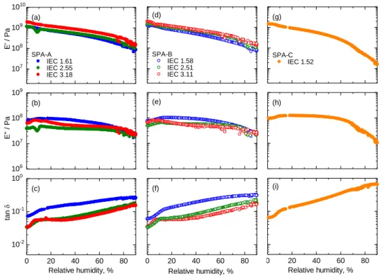
Humidity dependence of the storage modulus (E’), the loss modulus (E’’), and tan δ (= E’’/E’) of the SPA membranes was investigated by dynamic mechanical analysis (DMA) at 80 ºC, as shown in Figure 20. SPA-A and SPA-B membranes exhibited similar viscoelastic properties without obvious transition behavior under the given conditions. The storage modulus decreased with increasing humidity for both series of the membranes, suggesting that absorbed water molecules soften the membranes. SPA-C membrane showed larger loss in E’ and E’’ at high humidity compared to those of SPA-A and -B membranes due to lower molecular weight than those of SPA-A and -B. As a result of this, the alkylene groups in the main chain were likely to mitigate the effect of water on the viscoelastic properties because of the ease in approaching higher molecular weight.
Figure 21 shows tensile test results (stress/strain curves) of SPA membranes at 80 ºC and 60% RH. SPA-A and SPA-B membranes exhibited similar elongation properties with the Young’s moduli (0.9 - 2.5 GPa and 0.5 - 2.5 GPa), yield strengths (7.6 - 15 MPa and 4.9 - 12 MPa), and tenstile strains (15 - 81% and 12 - 99%), respectively, depending on their IEC. Briefly, as increasing the IEC value, the maximum strain decreased and the Young’s modulus and yield strength increased (Table 2). Compared to SPA-C membrane (1.52 mequiv g-1), SPA-A and -B membranes with similar IEC (1.61 and 1.58 mequiv g-1, respectively) exhibited higher Young’s moduli, higher yield strengths, and comparable maximum strains, indicating that the alkylene groups in the main chain enhanced the mechanical properties. The results are in agreement with the DMA data.
Table 2. Summary of Tensile Test Results of SPA-A, -B, and -C Membranes.
Membrane IEC (mequiv g-1) Maximum strain (%) Young's modulus (GPa) Yield strength (MPa) SPA-A 1.61 80.6 0.09 7.6 2.55 26.6 0.27 14.6 3.18 14.5 0.25 15.0 SPA-B 1.58 98.7 0.05 4.9 2.51 25.7 0.22 11.1 3.11 11.5 0.25 12.0 SPA-C 1.52 89.0 0.03 3.7
26 0 20 40 60 80 100 0 4 8 12 16
SPA-A SPA-B SPA-C
IEC 1.61 IEC 1.58 IEC 1.52
IEC 2.55 IEC 2.51 IEC 3.18 IEC 3.11 Strain, % S tr es s / M P a
Figure 20. Dynamic mechanical analyses of SPA membranes at 80 ºC as a function of the relative humidity; (a) E’, (b) E’’ and (c) tan σ for SPA-A, (d) E’, (e) E’’ and (f) tan σ of SPA-B and (g) E’, (h) E’’ and (i) tan σ of SPA-C, respectively.
Figure 21. Stress versus strain curves of SPA membranes at 80 ºC and 60% RH.
0 20 40 60 80 Relative humidity, % (g) (h) (i) SPA-C IEC 1.52 0 20 40 60 80 Relative humidity, % (d) (e) (f) SPA-B IEC 1.58 IEC 2.51 IEC 3.11 0 20 40 60 80 10-2 10-1 100 ta n Relative humidity, % (a) (b) (c) SPA-A IEC 1.61 IEC 2.55 IEC 3.18 107 108 109 1010 E ' / P a 106 107 108 109 E '' / P a
27
2.4.5. Fuel Cell Performance
Because of the balanced properties of water uptake, proton conductivity, mechanical properties, and their humidity dependence, SPA-B (IEC 2.51 mequiv g-1) was chosen for fuel cell evaluation. A membrane electrode assembly (MEA) was prepared from the SPA-B membrane (29 μm thick) with catalyst layers consisting of Pt/CB catalyst and Nafion binder for both the anode and the cathode. To evaluate the hydrogen permeability of the membrane, linear sweep voltammograms (LSVs) were measured at 80 ºC supplying humidified hydrogen and nitrogen to the anode and cathode, respectively, (Figure 22) prior to the performance evaluation. The oxidation current density of the permeated hydrogen was very small (ca. 3 μA cm-2) at 30% RH and higher (0.42 - 0.50 mA cm-2) at 100% RH. The hydrogen permeability of the SPA-B membrane was comparable to that of the SPAF membrane (0.40 mA cm-2 at 100% RH, 28 μm thick) and much smaller than that of Nafion NRE 212 membrane (1.45 mA cm-2 at 100% RH, 25 μm thick).
Figure 22. Linear sweep voltammograms (LSVs) of fuel cell with SPA-B (IEC = 2.51 mequiv g-1) membrane at 80 ºC, 30% RH and 100% RH.
Figure 23 shows polarization curves (ohmic (IR) drop-included) and ohmic resistances of the fuel cell with the SPA-B membrane operated with hydrogen and oxygen or air at 80 ºC, 100% RH and 30% RH. The open circuit voltages (OCVs) were 0.99 V (oxygen, 100% RH), 0.96 V (air, 100% RH), 1.01 V (oxygen, 30% RH), and 0.97 V (air, 30% RH), respectively. The high OCV values support low hydrogen permeability of the membrane as suggested by LSVs. At 100% RH, the ohmic resistance was 0.05 Ω cm2 both with oxygen and air, which was only slightly higher than that (0.02 Ω cm2) calculated from the proton conductivity (Figure 18b) and the thickness of the membrane. The results indicate reasonably good interfacial contact between the SPA-B membrane and the Nafion-based
0.1 0.2 0.3 0.4 0.5 0.6 0.7 -0.1 0 0.1 0.2 Potential vs. RHE / V C u rr e n t d e n si ty / m A cm -2 30% RH 100% RH 80 oC
28
catalyst layer. At 30% RH, the ohmic resistance was ca. 0.4 Ω cm2 at OCV and decreased with increasing the current density to 0.11 Ω cm2 with oxygen and 0.26 Ω cm2 with air, which were lower than that (0.51 Ω cm2) calculated from the proton conductivity and the thickness. The lower ohmic resistances in the operating fuel cell resulted from the back-diffusion of water from the cathode to the membrane. The effect was more pronounced with oxygen than with air since the oxygen flow rate (0.038 mL min-1 at 1 A cm-2) was slower than air flow rate (0.182 mL min-1 at 1 A cm-2) to have the same oxygen utility (40%). The ohmic resistance of SPA-B cell at 30% RH was smaller than that (0.33 Ω cm2 with air) of SPAF (IEC = 1.59 mequiv g-1)-cell due to the former’s higher IEC and higher proton conductivity.
Figure 23. IR-included polarization curves and ohmic resistances of fuel cell with SPA-B membrane (IEC = 2.51 mequiv g-1) at 80 ºC under humidity conditions (a) 100% and (b) 30% RH.
29
Figure 24. IR-free polarization curves and ohmic resistances for SPA-B cell (IEC = 2.51 mequiv g-1) at 80 ºC under humidity conditions (a) 100% and (b) 30% RH.
In order to evaluate the compatibility of the SPA-B and Nafion membrane and the Nafion-based catalyst layer in more detail, IR-corrected IV curves were plotted (Figure 24 and 25) and mass activities (MAs) of the Pt catalysts in the cathode at 0.85 V were calculated therefrom. The MAs of the SPA-B cell with air were 73 A g-1 at 100% RH which were lower than those of the SPAF cell (102A g-1 at 100% RH) and the Nafion cell (113A g-1 at 100% RH) under the same operating conditions. However, The MAs of the SPA-B cell with air were 58 A g-1 at 30% RH, respectively, which were slightly higher than those of the SPAF cell (51 A g-1 at 30% RH) and the Nafion cell (41 A g-1 at 30% RH) under the same operating conditions. Despite its higher proton conductivity and similarly phase-separated morphology, the SPA-B cell exhibited lower mass transport capability at the interface of the membrane/cathode catalyst layer than that of the SPAF cell, especially under higher RH test conditions. This could be explained by different degrees of water absorbability, which can cause an interfacial disconnect between the catalyst layer and the SPA-B membrane. The SPA-B cell shows comparable performance under lower RH test conditions. Less distinct hydrophobic/hydrophilic phase separations would be responsible, in particular, at low humidity where proton transport to the catalyst surface became more crucial.
30
Figure 25. IR-free polarization curves and ohmic resistances for SPA-B cell (IEC = 2.51 mequiv g-1) and Nafion 212 at 80 ºC under humidity conditions (a) 100% and (b) 30% RH.
To evaluate the durability of the SPA-B membrane, an OCV hold test was carried out with hydrogen and air (Figure 26). The OCV was initially 0.98 V and decreased to 0.86 V after 1000 h with an average decay of -120 μV/h. No sudden drop of OCV was observed during the test, indicating no serious damage on the membrane such as pinholes. After the OCV hold test for 1000 h, the I-V performance was re-evaluated under the same operating conditions (Figure 27). The OCV decreased after the test from 0.99 V to 0.95 V (oxygen, 100% RH), 0.96 V to 0.91 V (air, 100% RH), 1.01 V to 0.85 V (oxygen, 30% RH), and 0.97 V to 0.90V (air, 30% RH), respectively. The post-OCV hold test cell exhibited lower fuel cell performances than those of the pristine membrane cell. The loss in the performance, however, was not significant but rather minor with oxygen at 100% RH, followed by air at 100% RH and oxygen at 30% RH, and air at 30% RH. Since the ohmic resistances of the post-OCV hold test cell were similar to those of the pristine membrane (except for air at 30% RH), the lowered fuel cell performances were more likely caused by the degradation of the Nafion-based catalyst layers. This idea was supported by the IR-corrected curves in Figure 28, where the lower cathode performances were confirmed with the post-OCV hold test cell. The results support minor degradation of the SPA-B membrane under the test conditions.
31 0 200 400 600 800 1000 0.4 0.5 0.6 0.7 0.8 0.9 1.0 C e ll vo lta g e / V Time / h
The fuel cell was disassembled, and the SPA-B membrane was recovered by carefully removing the catalyst layers from both sides of the membrane to analyze the changes in the molecular weight and chemical structure. The recovered SPA-B membrane was still bendable. The GPC curves of the post-test SPA-B shifted to the longer retention time resulting in the lower number-averaged molecular weight (Mn = 30 kDa) with larger dispersity (PDI = 7.0) than those of the pristine SPA membrane (Figure 29). 19F NMR spectrum did not show practical changes suggesting chemical robustness of the perfluoroalkylene groups (Figure 30a). In contrast, the 1H NMR spectrum of the post-test SPA-B membrane differed from that of the pristine membrane (Figure 30b). The peaks assignable to the aliphatic protons (no. 9 - 11) and aromatic protons (no. 5 - 8 and 12 - 14) were smaller for the post-test membrane. The results suggest some degradation of the components derived from the monomer 2, accountable for slightly higher ohmic resistance of the post-test fuel cell with air at 30% RH.
32
Figure 27. IR-included polarization curves and ohmic resistances of the fuel cell of SPA-B membrane before and after the OCV hold test; (a) and (b) with air and (c) and (d) with oxygen at 80oC, 100% and 30%RH.
Figure 28. IR-free polarization curves and ohmic resistances of the fuel cell of SPA-B membrane before and after the OCV hold test; (a) and (b) with air and (c) and (d) with oxygen at 80oC, 100% and 30%RH.
33
5 10 15
retention time / min
U V a b so rb a n ce a t 2 7 0 n m / a .u . OCV test Before After
Figure 29. GPC profiles of SPA-B membrane before and after the OCV hold test.
Figure 30. (a) 19F and (b) 1H NMR spectra of SPA-B membrane before and after the OCV hold test in DMSO-d6 at 80 oC.
34
2.5. Conclusions
We have successfully synthesized two types of sulfonated terpolymers (SPA) containing perfluoroalkylene and alkylene groups to investigate the effect of these (perfluorinated) aliphatic groups on the membrane and interface properties. Both series of terpolymers provided bendable membranes by solution casting. Introducing alkylene groups enabled higher IEC membranes than the previous sulfonated copolymer (SPAF) membranes without alkylene groups. The effect of the aliphatic groups on the membrane properties was significant. Because of the less hydrophobic nature of the alkylene groups than the perfluoroalkylene groups, the hydrophilic/hydrophobic phase-separated morphology of SPA-A membranes with higher alkylene content was less distinct. SPA-B membranes exhibited slightly higher proton conductivity and similar water uptake compared to those of SPA-A membranes reflecting more developed morphology of the former ones with better interconnected ionic channels. Because of IEC higher than that of SPAF membrane, SPA membranes showed much higher proton conductivity. The alkylene groups in the main chain also impacted on the mechanical properties. SPA-A and -B membranes exhibited higher Young’s moduli, higher yield strengths and comparable maximum strains compared to those of SPA-C membrane. The SPA-B membrane showed very low hydrogen permeability as suggested by low hydrogen oxidation current densities in LSVs and high OCVs in a fuel cell. The ohmic resistance of the fuel cell was reasonable for high proton conductivity of the SPA-B membrane. The compatibility of the SPA-B membrane with Nafion-based catalyst layers was not as good as that of SPAF membrane probably because of the inefficient mass transport capability at their interfaces in particular at low humidity. The OCV hold test of the fuel cell revealed high oxidative durability of the SAP-B membrane with small loss in OCV value (the average decay of -120 μV/h) for 1000 h. The post-test durability analyses of the SPA-B membrane suggested small but not severe degradation in the alkylene groups in the main chain. By tuning the alkylene chain length and/or terpolymer composition, incompatibility with the catalyst layers and chemical vulnerability would be mitigated.
35
References
[1] M. A. Hickner, H. Ghassemi, Y. S. Kim, B. R. Einsla, J. E. McGrath, Chem. Rev., 2004, 104, 4587-4612.
[2] H. Zhang, P. K. Shen, Chem. Rev., 2012, 112, 2780-2832.
[3] T. Higashihara, K. Matsumoto, M. Ueda, Polymer, 2009, 50, 5341-5357. [4] J. Miyake, K. Miyatake, Polym. J, 2017, 49, 487-495.
[5] J. Ahn, H. Lee, T. Yang, C. Kim and B. Bae, J. Polym. Sci. Part A: Polym. Chem., 2014, 52, 2947-2957
[6] C. H. Park, C. H. Lee, M. D. Guiver and Y. M. Lee, J. Prog. Polym. Sci., 2011, 36, 1443-1498 [7] M. A. Hickner, H. Ghassemi, Y. S. Kim, B. R. Einsla and J. E. McGrath, Chem. Rev., 2004, 104,
4587-4612
[8] J. Miyake, R. Taki, T. Mochizuki, R. Shimizu, R. Akiyama, M. Uchida and K. Miyatake, Sci.
Adv., 2017, 3, eaao0476
[9] T. Mochizuki, M. Uchida, K. Miyatake, ACS Energy Lett., 2016, 1, 348-352.
[10] H. Ono, J. Miyake, S. Shimada, M. Uchida, K. Miyatake, J. Mater. Chem. A, 2015, 3, 21779-21788
36
Chapter 3. Sulfonated aromatic polymers containing
hexafluoroisopropylidene groups
3.1 Introduction
More recently, our laboratory has developed a simpler version of sulfonated polyphenylene composed only of phenylene rings and sulfonic acid groups. [1] By carefully optimizing the m-/p- composition and sulfonic acid concentration, we proved that sulfonated polyphenylene (SPP-QP, Figure 31) with a very simple polymer structure provided thin membranes with bendability, high proton conductivity, and excellent chemical stability. The SPP-QP membrane functioned well in an operating hydrogen/oxygen fuel cell with high performance and durability.
Figure 31. Chemical structures of sulfonated poly(phenylene) (SPP-QP) composed only of phenylene rings and sulfonic acid groups.
The results prompted us to further investigate the polymer structure for better performing proton conductive aromatic ionomers. In the present research, I replaced quinquephenylene groups (five consecutive phenylene rings in SPP-QP) with hexafluoroisopropyl biphenylene groups, since the latter contain an even simpler structure and could be prepared in a single step in high yield from the commercially available inexpensive chemicals (e.g., bisphenol-AF). We report herein synthesis and characterization of a novel series of sulfonated phenylene polymers containing hexafluoroisopropylidende groups in the main chain. Their properties, including fuel cell performance and durability, are compared, in detail, with those of our SPP-QP membranes.
3.1. Measurements
1H and 19F NMR spectra were measured a JEOL JNM-ECA ECX500 using deuterated dimethyl sulfoxide (DMSO-d6) containing 1 vol% tetramethylsilane as internal reference.
The molecular weight of the monomers and copolymers was measured via gel permeation chromatography (GPC) equipped with a Jasco 805 UV detector. Dimethylformamide (DMF)
37
containing 0.01 M lithium bromide (LiBr) was used as the eluent. Shodex KF-805L and SB-803HQ columns were used for the measurement of polymers and monomers, respectively. Molecular weight was calibrated using standard polystyrene samples.
Ion exchange capacity (IEC) of the membranes was measured by titration at r.t. A piece of dry membrane in acid form was immersed into 2M NaCl aqueous solution for at least 24 h. The released HCl in the solution was titrated with 0.01 M NaOH aqueous solution. The IEC was calculated using the following equation; IEC (mequiv. g-1) = ΔVNaOH × CNaOH / Wd, where ΔVNaOH is the consumed volume of NaOH solution, CNaOH is the concentration of NaOH solution, and Wd is the weight of the dry membrane.
Morphology of the membranes was analyzed by transmission electron microscopy (TEM). For TEM observation, the membranes were stained with lead ions (Pb2+) by ion exchange of sulfonic acid groups in 0.5M Pb(OAc)2 aqueous solution, rinsed with deionized water, and dried in a vacuum oven for 12h. The stained samples were embedded in epoxy resin, sectioned into 50nm slices with a Leica microtome Ultracut UCT, collected by copper grids, and then investigated with a Hitachi H-9500 TEM at an acceleration voltage of 200kV.
The SAXS measurement was conducted using a Rigaku NANO-Viewer diffractometer equipped with a temperature/humidity-controlled chamber. The membrane was equilibrated for at least 2h under each humidity condition from 30% to 90% relative humidity (RH) at 80 ºC.
Proton conductivity and water uptake were measured in a temperature and humidity controllable chamber at 80ºC from 95% to 20% RH. Ion conducting resistances (R) were determined from the impedance plot. The proton conductivity (σ) was calculated according to the following equation; σ =L/(S × R), where L, S, and R are the thickness of the membrane, the area of the electrodes, and the resistance of the membrane, respectively.
Dynamic mechanical analyses (DMA) of the membranes (0.5cm × 3cm) were carried out with an ITK DVA-225 dynamic viscoelastic analyzer at 80 ºC from 0% to 90% RH. The storage modulus (E’), loss modulus (E’’), and tan σ (= E’’/E’) of the membranes were recorded.
Tensile strength of the membranes was measured in a temperature and humidity controllable chamber. Stress versus strain curves were obtained for samples cut into a dumbbell shape (DIN-53503-S3, 35mm × 6mm (total) and 12 mm × 2 mm (test area)). The measurement was conducted at 80 ºC and 60% RH at a stretching rate of 10 mm min-1.
38
gas permeation measurement apparatus equipped with a Yanaco G2700T gas chromatograph (GC) with a Porapak Q column and a thermal conductivity detector. Argon and helium were used as carrier gases for the measurement of hydrogen and oxygen, respectively. Membranes were placed in the center of the cells having gas inlet/outlet on both sides of membranes. The test gas was supplied to one side of the membranes and the carrier gas was supplied to the other side of membranes. The same humidity conditions were applied to both test and carrier gases to ensure homogeneous wetting of the membranes. Then, flow gas was sampled and subjected to the GC to quantify the test gas permeated through the membrane. The gas permeability coefficient of the membranes Q [cm3 (STP) cm cm-2 s-1 cmHg-1] was calculated by the following equation: Q = 273/T × 1/A × B × 1/t × l × 1/(76 - PH
2O), where
T (K) is the absolute temperature, A (cm2) is the permeation area, B (cm3) is the volume of permeated test gas, t (s) is the sampling time, l (cm) is the thickness of the membrane, and PH2O (cmHg) is the
water vapor pressure.
3.2. Experimental
3.2.1. Materials
2,5-Dichlorobenzenesulfonic acid dehydrate (SP) (TCI), 4,4’-(hexafluoroisopropylidene)diphenol (TCI), dichlorotriphenylphosphorane (Sigma-Aldrich), bis(1,5-cyclooctadiene)nikel(0) (Ni(COD)2) (> 95%, Kanto Chemical), 2,2’-bipyridine (> 99%, Kanto Chemical), potassium carbonate (K2CO3) (Kanto Chemical), sodium chloride (NaCl) (Kanto Chemical), dimethyl sulfoxide (DMSO) (> 99%, Kanto Chemical), and toluene (> 99%, Kanto Chemical) were used as received. 2,2-Bis(4-chlorophenyl)hexafluoropropane (BAF) was synthesized according to the literature.[2]
3.2.2. Polymerization
A series of SBAF copolymers were synthesized as follows. A 100 mL three-neck flask was charged with 2,2-bis(4-chlorophenyl)hexafluoropropane (BAF, 0.2984 g, 0.8 mmol), 2,5-dichlorobenzenesulfonic acid dehydrate (SP, 0.3683 g, 1.4 mmol), K2CO3 (0.2322 g, 1.68 mmol), 2,2’-bipyridine (1.4498 g, 9.24 mmol), DMSO (6 mL), and toluene (6 mL). The mixture was heated in the temperature-controlled oil bath at 170 °C for 2 h with a Dean Stark trap under N2. After azeotropic dehydration, the mixture was cooled to 80 °C. To the mixture, Ni(COD)2 (1.2708 g, 4.62 mmol) was added. After the reaction at 80 °C for 3 h, the mixture was poured into large excess of 6 M HCl to precipitate the product. The crude product was washed with concentrated HCl and deionized water
![Figure 9. The chemical structure and TEM image of Block SPAES (IEC 2.8 mequiv g -1 ); high concentration of sulfonic acid group on hydrophilic part of multi-block SPES polymers [31]](https://thumb-ap.123doks.com/thumbv2/123deta/7693529.1216642/12.892.144.761.732.934/figure-chemical-structure-block-concentration-sulfonic-hydrophilic-polymers.webp)
![Figure 10. The chemical structure of locally and densely sulfonated poly(ether sulfone)s membrane [32]](https://thumb-ap.123doks.com/thumbv2/123deta/7693529.1216642/13.892.167.742.313.481/figure-chemical-structure-locally-densely-sulfonated-sulfone-membrane.webp)