Original article
Biomechanical analysis of immediately loaded implants according to the “All-on-Four” concept
Satoshi Horita DDS *, Tsutomu Sugiura DDS, PhD,
Kazuhiko Yamamoto DDS, PhD, Kazuhiro Murakami DDS, PhD, Yuichiro Imai DDS, PhD, Tadaaki Kirita DDS, DMSc
Department of Oral and Maxillofacial Surgery, Nara Medical University, Nara, Japan
a b s t r a c t
Purpose: The purpose of this study was to investigate the biomechanical behavior of immediately loaded implants in an edentulous mandible according to the “All-on-Four”
concept.
Methods: A 3D-finite element model of an edentulous mandible was constructed. Four implants were placed between the bilateral mental foramen according to “All-on-Four”
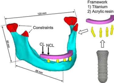
concept. A framework made of titanium or acrylic resin between the bilateral first molars was modeled. Immediate loading and a delayed loading protocol were simulated. A vertical load of 200N was applied at the cantilever or on the abutments region of the distal implants, simulating the absence of a cantilever.
Results: The peak principal compressive strains in the immediate loading models resulted in 24.0 –35.8% and 26.4 –39.0% increases compared with the delayed loading models under non- cantilever loading and cantilever loading, respectively. The loading position greatly affected the principal compressive and tensile strain values. The peak principal compressive strains in non-cantilever loading resulted in a 45.3 –52.6% reduction compared with those in cantilever loading. The framework material did not influence the peak compressive and tensile strain. The maximum micromotion at the bone –implant interface in the immediate loading models was 7.5 –14.4 m m.
Conclusions: Mandibular fixed full-arch prostheses without cantilevers may result in a favorable reduction of the peri-implant bone strain during the healing period, compared with cantilevers. The maximum micromotion was within the acceptable limits for uneventful implant osseointegration in the immediate loading models. Framework material did not play an important role in reducing the peri-implant bone strain and micromotion at the bone – implant interface.
ã 2016 Japan Prosthodontic Society. Published by Elsevier Ltd. All rights reserved.
a r t i c l e i n f o
Article history:
Received 1 August 2015 Received in revised form 6 July 2016
Accepted 8 August 2016 Available online xxx
Keywords:
All-on-Four concept Finite element analysis Immediate loading Cantilever loading Framework material
1. Introduction
Implant-supported fixed full-arch prostheses are being estab- lished as a treatment option for edentulous mandibles.
* Corresponding author at: Department of Oral and Maxillofacial Surgery, Nara Medical University, 840 Shijo-cho, Kashihara City, Nara 634-8521, Japan. Fax: +81 744 29 8876.
E-mail address: [email protected] (S. Horita).
http://dx.doi.org/10.1016/j.jpor.2016.08.002
1883-1958/ã 2016 Japan Prosthodontic Society. Published by Elsevier Ltd. All rights reserved.
journalofprosthodontic research xxx (2016) xxx–xxx JPOR362No.ofPages11
Available online at www.sciencedirect.com
ScienceDirect
j o u r n a l h o m e p a g e : w w w . e l s e v i e r . c o m / l o c a t e / j p o r
According to the original Brånemark protocol, five – six im- plants should be placed in the interforaminal region of the mandible to support a fixed dental prosthesis [1,2]. Long-term clinical data on implant and prosthesis survival have con- firmed that fixed prostheses on four implants in the edentu- lous mandible showed similar results to those of patients treated with more implants [1,3].
In edentulous patients, the anatomic limitations of the residual alveolar bone due to bone resorption or a mandibular canal can cause problems for the insertion of dental implants, often requiring bone augmentation procedures. A new proto- col, the so-called All-on-Four concept has been proposed as an alternative to bone augmentation procedures. The principle of the “ All-on-Four ” concept is the use of four implants in the anterior part of the complete edentulous jaw to support a provisional, fixed, and immediately loaded prosthesis [4]. The
“ All-on-Four ” concept offers a less invasive option because it requires fewer implants, with bilateral distal implants inserted at an inclination of 30
to decrease the cantilever length. The
“ All-on-Four ” concept has been successful according to short- term clinical studies [4 – 8]. However, there have been very few long-term studies.
The stress/strain concentration can cause microdamage accumulation and can induce bone resorption [9,10]. The predictability and long-term success of implant treatment are greatly influenced by the biomechanical environment. The tilting of distal implants allows for a reduction in the cantilever length, resulting in decreased peri-implant bone stress [11,12].
Previous biomechanical studies have reported that the “All- on-Four ” configuration resulted in favorable reduction of stresses in the bone, framework, and implants in delayed loading models [11,13]. However, there has been little biomechanical evidence for immediately loaded implants according to the “All-on-Four” concept. In particular, excessive micromotion could cause osseointegration failure between the bone and implant [9,14]. To date, there have been no studies evaluating the primary stability of immediately loaded implants according to the “ All-on-Four ” concept.
The framework material is an important factor affecting the stress/strain developed in implants, prostheses, and peri- implant bone. Controversy exists regarding framework mate- rials under the conditions of immediate loading. Some authors have recommended using metal frameworks because of their high rigidity, compared to all-acrylic resin prostheses [15,16].
However, other authors have used all-acrylic resin prostheses without metal frameworks and have also reported high survival rates [17 – 19].
The purpose of this study was to investigate the bio- mechanical behavior of immediately loaded implants accord- ing to the “All-on-Four” concept in an edentulous mandible.
2. Materials and methods 2.1. Finite element model
The 3D geometry of the edentulous mandible was constructed using finite element analysis (FEA) software (Mechanical Finder, version 6.2, Extended Edition, Research Center of Computational Mechanics, Tokyo, Japan) from the
computerized tomographic (CT) scan data of a 62-year-old man. A threaded implant (Institut Straumann, Waldenburg, Switzerland) with a 4.1-mm diameter and a 10-mm length was simulated in this study. An implant and a straight or angulated abutment 6mm high was modeled as one piece using 3D modeling software. The two anterior implants were placed in the right and left lateral incisor areas. Two additional posterior implants were also placed just anterior to the mental foramen with a distal inclination of 30
to the anterior implant (Fig. 1).
For delayed loading models, the implant was assumed to achieve complete osseointegration at the bone – implant inter- face. For immediate loading models, the contact interface (non-osseointegration) between the implant and bone was simulated. The friction coefficient was set to 0.3 [20,21]. A framework between the bilateral first molars was modeled.
The framework was designed as a geometric solid, 5mm high and 6mm wide, in a horseshoe configuration following the shape of the mandible. The cantilever extension was 11.5mm (Fig. 1). Four-node tetrahedral elements were used to construct a finite element model, and the total numbers of elements and nodes were 343,361 and 68,602, respectively. All of the experimental procedures were conducted with the ethical approval of the Nara Medical University.
2.2. Material properties
The isotropic linear elasticity was adopted in the finite element models and inhomogeneity for the bone was assumed. First, an average CT value for each element was calculated. A linear regression equation was created based on the CT values of the calibration phantom. An excellent linear correlation between Hounsfield units (HUs) and corresponding hydroxyapatite density ( r ) was established:
r ¼ 0 : 6618 HU þ 9 : 84 mg = cm
3; R
2¼ 0 : 999 :
Next, the CT value for each element was converted to a bone density. Finally, Young’s modulus for each bone density was calculated using the equation proposed by Keyak [22] (Table 1).
Distributions of Young ’ s modulus in the peri-implant bone are shown in Fig. 2. Because the cortical bone density of the mandible ranges from 1000 to 1800 HU [23,24], the area with bone density over 1000 HU, which is equivalent to 4583MPa, was defined as cortical bone. Poisson’s ratio for the bone was set to 0.3 [25]. The material properties of the titanium implant were obtained from previous data [25]. Different framework material models, made of titanium or acrylic resin, were simulated [11] (Table 2).
2.3. Loading and constraint conditions
With fixed prostheses supported by implants, the average of maximum occlusal force was approximately 200N for first premolar and molars [26]. Two types of loading position were simulated.
Cantilever loading: A vertical load of 200N was applied at
the right terminal of the framework [13].
Non-cantilever loading: A vertical load of 200N was applied on the abutment region of the right distal implant, simulating the absence of a cantilever [27].
Regarding boundary conditions, the nodes of the condylar and coronoid process regions of the model were constrained in all directions [13] (Fig. 1).
2.4. Analysis of strains and micromotion
Analyses were performed to calculate the principal compres- sive strain (minimum principal strain) and principal tensile strain (maximum principal strain) around the implants and the micromotion at the bone – implant interface. To evaluate Fig. 1 – Finite element model. A vertical load of 200N was applied at the cantilever or on the abutment region of the right distal implant, simulating the absence of a cantilever. CL: cantilever loading; NCL: non-cantilever loading.
Fig. 2 – Distribution of Young ’ s modulus in the peri-implant bone. The height, width, and thickness of the buccal, lingual, crestal and inferior cortical bone of the mandible (mm) were measured.
j o u r n a l o f p r o s t h o d o n t i c r e s e a r c h x x x ( 2 0 1 6 ) x x x – x x x 3
JPOR362No.ofPages11
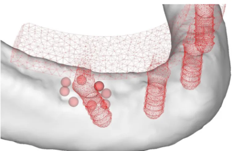
the principal compressive and tensile strains, eight 1-mm spheres were placed at the alveolar crest for each implant in the similar manner as in the previous report [28] (Fig. 3). The mean of the principal compressive and tensile strain values in multiple solid elements contained in the sphere was used as the typical strain value. The absolute maximum value in these spheres was used as the peak strain (hereinafter referred to as the “ peak strain ” ) value of the model. The micromotion was computed as a relative displacement between two nodes (a node of the bone side and a node of the implant side) of elements on the interface.
In FEA studies to evaluate mechanical stress/strain in the peri-implant bone, it is customary to use stresses/strains of various kinds, such as von Mises stress, equivalent strain, the maximum, the minimum principal stress/strain and the maximum shear stress/strain. The maximum principal stress/strain is suited for the observation of tensile stress/
strain and the minimum one for the compressive. Since bone has both ductile and brittle response, the use of principal stress/strain is appropriate to evaluate yielding/failure behav- ior [29]. Thus, in this study, the principal strains were evaluated.
2.5. Convergence test
The convergence test of the finite element models was performed to verify the mesh quality, and the convergence criterion was set to be less than 3% changes of the total strain energy of all of the elements between the elements (Fig. 4).
Based on the results of the convergence testing, a minimum element size of 0.2mm was set for the meshing in all of the finite element models.
3. Results
3.1. Strain distribution
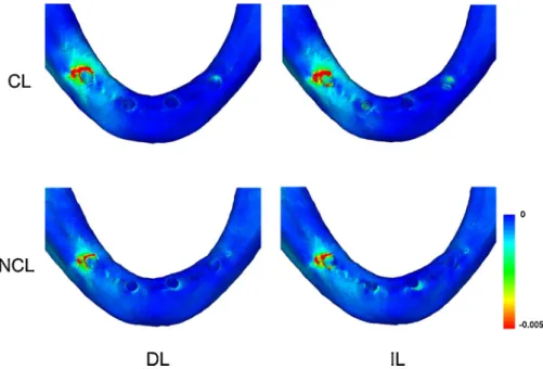
The peak principal compressive and tensile strains were observed in the bone around the neck of the right distal implant in all of the models (Fig. 5). In the delayed loading models, the principal compressive and tensile strains were concentrated only in the crestal cortical bone, whereas the principal strains were distributed in both the crestal cortical bone and the cancellous bone around the threads of the implant in the immediate loading models. Peak principal compressive strains were observed at the distal crestal cortical bone around the distal implant regardless of loading protocol.
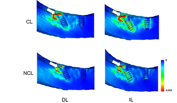
Peak principal tensile strains were located at the lingual region and the distal region in the crestal cortical bone in the delayed loading models and the immediate loading models, respec- tively (Figs. 6 and 7).
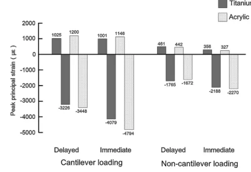
Peak principal compressive strains in the immediate loading models resulted in 24.0 – 35.8% and 26.4 – 39.0% increases compared with the delayed loading models under the non- cantilever loading and cantilever loading, respectively. In contrast, the principal tensile strain value depended little upon the loading protocol, although the peak principal tensile strains in the delayed loading models were slightly higher than those in the immediate loading models. The loading position greatly affected the principal compressive and tensile strain values. The peak principal compressive and tensile strains in non-cantilever loading resulted in 45.4 – 52.6% and 55.0 – 71.5%
reduction compared with the cantilever loading, respectively (Fig. 8).
Fig. 3 – Measurement points for principal strains in bone around the implant.
Table 1 – Relationship between bone density and Young ’ s modulus.
Bone density (g/cm
3) Young ’ s modulus (MPa)
0<
r
20.27 E=33,900r
2.200.27<
r
<0.6 E=5307r
+ 4690.62
r
E=10,200r
2.01Table 2 – Material properties.
Material Young ’ s modulus (MPa) Poisson ’ s ratio
Titanium 110,000 0.35
Acrylicresin 3520 0.40
The framework material did not influence the peak principal compressive and tensile strain under non-cantilever loading. Under cantilever loading, the peak principal com- pressive and tensile strains in the titanium framework models were at most 14.9% and 14.6% less than those in the acrylic resin framework models, respectively (Fig. 8).
3.2. Micromotion at the bone – implant interface
The maximum micromotion was observed at the crestal region around the distal implant close to the loading position in all of the models. The micromotion in the acrylic resin framework model was greater than that in the titanium framework. The maximum micromotion was the greatest (14.4 m m) under
cantilever loading for the acrylic resin framework model. The other models showed similar micromotion values (Table 3).
4. Discussion
As photoelastic [30] and FEA studies [11,31,32] have indicated that the bone strains are concentrated around the distal implant, the present study also showed the principal com- pressive and tensile strain concentrations around the distal implant. In the delayed loading models, the principal compressive and tensile strains were concentrated only in the crestal cortical bone, whereas the principal strains were distributed in both the crestal cortical bone and the cancellous bone around the threads of the implant in the immediate loading models. This result was consistent with previous reports that showed strain concentrations along the implant body in the delayed and immediate loading models [11,13,33 – 36].
Fig. 4 – The result of convergence testing in the model with a titanium framework under cantilever loading.
Fig. 5 – Distribution of principal compressive strain (titanium framework model). Similar trends were observed in the principal tensile strain distribution (data not shown). CL: cantilever loading; NCL: non-cantilever loading; DL: delayed loading; IL:
immediate loading.
j o u r n a l o f p r o s t h o d o n t i c r e s e a r c h x x x ( 2 0 1 6 ) x x x – x x x 5
JPOR362No.ofPages11
In the immediately loaded implants, higher stress/strain develops in the cortical bone and cancellous bone, because only compressive and frictional forces are transferred via the contacting interfaces, compared with the bonded interfaces of the delayed implants [20,37,38]. The increase in bone strain (24.0 –39.0%) observed in the present study was similar to that reported by Huang et al. (28.0 – 63.0% increase) [20]. Frost [39]
considered 4000 me a possible threshold for pathologic bone
overload and suggested that higher strains would lead to the accumulation of microdamage, resulting in bone resorption.
Pattin et al. [40] demonstrated that the critical damage strain threshold was 2500 me in tension and 4000 me in compression.
Immediate loading models under cantilever loading showed peak principal compressive strain greater than 4000 me .
Although well-controlled immediate loading accelerates tissue mineralization at the peri-implant bone [41], over- loading and fracturing occur more readily in healing bone than in normal bone [42]. Occlusal loading in the healing period might be sufficient to cause microdamage in the peri-implant bone, although the same load will not do so after healing and Fig. 6 – Distribution of principal compressive strain in the mesiodistal cross-sections (titanium framework model). CL: cantilever loading; NCL: non-cantilever loading; DL: delayed loading; IL: immediate loading. The arrows indicate sites where the peak principal compressive strains were generated.
Fig. 7 – Distribution of principal tensile strain in the mesiodistal cross-sections (titanium framework model). CL: cantilever
loading; NCL: non-cantilever loading; DL: delayed loading; IL: immediate loading. The arrows indicate sites where the peak
principal tensile strains were generated.
adaptation of the bone around the implant [43]. Although the strain value in the healing process could not be directly compared with that threshold, immediate loading of the mandibular fixed full-arch prosthesis with cantilever might indicate a risk of overloading.
The loading position greatly affected the principal com- pressive and tensile strain values. The results of the present study were in accordance with those of previous studies which demonstrated that the increase in cantilever length was directly proportional to the increase in stress concentrations around the implants [31]. Authors have shown that cantilever length played an important role in the peri-implant stress/
strain distribution [11,31,44]. The peak compressive stress in the 15-mm cantilever models resulted in a 33% increase compared with the 5-mm cantilever models [11]. The maxi- mum von Mises stress in the cortical bone in the cantilever model was 1.5 times greater than that without the cantilever [44]. Therefore, in immediately loaded restorations, clinicians seem to have desired to avoid occlusal force at the cantilever to minimize the risk of peri-implant bone overloading. According to many clinical reports, an acrylic provisional prosthesis is usually designed with 10 teeth with no occlusal contact with the second premolar or the first molar area [7,45,46]. In contrast, several authors have reported promising clinical outcomes in which full-arch definitive prostheses were positioned immediately after implant placement [19,47]. In these cases, the cantilevers were typically extended to the first molar region, and cantilever loading was allowed, although the patients ate a soft diet for 2 months [19]. From a biomechanical point of view, a mandibular fixed full-arch prosthesis without a cantilever is recommended during the
healing period, because non-cantilever loading effectively reduces the peri-implant bone strain under immediate loading.
Previous studies have shown that variations in the stiffness of the framework materials did not demonstrate significant effects on the peri-implant stress values under non-cantilever loading [44,48]. Under cantilever loading, the lower the Young ’ s modulus of the framework is, the greater the occlusal load is that is applied to the distal implant [31]. Thus, more load is transferred to the bone around distal implant in acrylic resin frameworks than in metal frameworks, which might be the reason why the micromotion at the bone – implant interface in the acrylic resin framework model was greater than that in the titanium framework. However, even under cantilever loading situations, the framework material did not significantly affect the peri-implant bone strain; the peak principal compressive and tensile strains in the titanium framework models were at most 14.9% and 14.6% less than those in the acrylic resin framework models, respectively. Thus, we believe that framework material may not play an important role in reducing the peri-implant bone strain under vertical loading.
Primary implant stability is essential for the uneventful formation of bone tissue at the bone – implant interface [9,14].
The success of dental implants is not related to the timing of loading, but rather to the critical function of micromotion, which should not exceed 50 –100 m m at the bone –implant interface [49]. The maximum micromotion values of the non- cantilever models ranged from 7.5 to 8.6 m m, which was in
agreement with those reported in previous FEA studies [36,50 – 52]. For example, Chang et al. [52] showed that a maximum micromotion was 8.5 – 15.0 m m in an immediately loaded, single implant model with a vertical load of 300N. Kao et al. [51]
reported that the maximum micromotion value was 11.1 m m
in FEA, in which the data on pull-out forces were consistent with the result of other experiment. The micromotion values observed in the present study were less than these thresholds, Fig. 8 – The peak values of the principal strains.
Table 3 – Micromotion at bone –implant interface ( m m).
Material Cantilever loading Non-cantilever loading
Titanium 9.0 7.5
Acrylicresin 14.4 8.6
j o u r n a l o f p r o s t h o d o n t i c r e s e a r c h x x x ( 2 0 1 6 ) x x x – x x x 7
JPOR362No.ofPages11
which would indicate that osseointegration between the bone and implant would be possible for immediately loaded implants according to the “ All-on-Four ” concept, irrespective of the loading position and framework material. This finding might explain why the “ All-on-Four ” concept was successful according to the clinical study results [4 – 8].
Bellini et al. [11] analyzed bone stress in a tilted implant model similar to that in the present study, with a 100-N load at the cantilever. They showed a peak principal compressive stress of 24MPa in the 15-mm cantilever model, which was equivalent to the principal compressive strain of 3265 me
under loading condition of 200N. The peak principal compres- sive strain in the delayed loading model under cantilever loading in the present study was 3226 me . Although the
model geometry, material property and boundary conditions were not identical, the results of this study were in agreement with those of Bellini et al.; hence, the model of this study should be considered to have been validated accurately by a published report. In future analyses, the obtained strain data should be validated with strain gauge measurements using human cadaver mandible.
There were limitations of this finite element model. In the present study, four-node tetrahedral elements were used.
However, higher-order elements such as ten-node tetrahedral element with quadratic shape function would give more accuracy for simulated results. Although isotropic linear elasticity of the material properties was assumed, altering mandibular properties with anisotropic assumption may result in different strain distributions [20]. This study incorporated frictional contact area for the bone – implant interface to simulate immediate stability after implantation, where perfect contact of the implant with the surrounding bone was assumed. However, clinically, the implant may be in partial contact with the bone. Although biomechanical study has revealed that the stress/strain distribution around an implant strongly depends on in vivo load direction [29], the load was applied in a fixed direction. Regarding the framework, only bending motion at distal loading was simulated. Howev- er, bending moment and twisting moment would be applied on the framework. Nonetheless, in agreement with other numer- ical studies [11,13,31 – 35], the present assumptions can be accepted, in a computational sense, to assess the biomechani- cal behavior of fixed full-arch prostheses [53].
5. Conclusions
Considering the limitations of this study, the following could be concluded regarding the biomechanical behavior of immediately loaded implants according to the “All-on-Four”
concept in an edentulous mandible.
1. Mandibular fixed full-arch prostheses without cantilevers may result in a favorable reduction of the peri-implant bone strain during the healing period, compared with
cantilevers.
2. The maximum micromotion at the bone – implant interface was within the acceptable limits for uneventful implant osseointegration in the immediate loading models.
3. The framework material did not play an important role in reducing the peri-implant bone strain and micromotion at the bone – implant interface.
Acknowledgment
This work was supported by a Grant-in Aid for Scientific Research from the Japan Society for the Promotion of Science (No. 25861893).
REFERENCES
[1] Brånemark PI, Svensson B, van Steenberghe D. Ten-year survival rates of fixed prostheses on four or six implants ad modum Brånemark in full edentulism. Clin Oral Implants Res 1995;6:227 –31.
[2] Adell R, Lekholm U, Rockler B, Brånemark PI. A 15-year study of osseointegrated implants in the treatment of the edentulous jaw. Int J Oral Surg 1981;10:387 –416.
[3] Gallucci GO, Morton D, Weber HP. Loading protocols for dental implants in edentulous patients. Int J Oral Maxillofac Implants 2009;24:132 –46.
[4] Patzelt SB, Bahat O, Reynolds MA, Strub JR. The All-on-Four treatment concept: a systematic review. Clin Implant Dent Relat Res 2014;16:836–55.
[5] Maló P, Rangert B, Nobre M. All-on-Four immediate-function concept with Brånemark System implants for completely edentulous mandibles: a retrospective clinical study. Clin Implant Dent Relat Res 2003;5:2 –9.
[6] Maló P, de Araújo Nobre M, Rangert B. Short implants placed one-stage in maxillae and mandibles: a retrospective clinical study with 1 to 9 years of follow-up. Clin Implant Dent Relat Res 2007;9:15 –21.
[7] Agliardi E, Panigatti S, Clericò M, Villa C, Malò P. Immediate rehabilitation of the edentulous jaws with full fixed prostheses supported by four implants: interim results of a single cohort prospective study. Clin Oral Implants Res 2010;21:459 –65.
[8] Balshi TJ, Wolfinger GJ, Slauch RW, Balshi SF. A retrospective analysis of 800 Brånemark System implants following the All- on-Four
TMprotocol. J Prosthodont 2014;23:83 –8.
[9] Brunski JB, Puleo DA, Nanci A. Biomaterials and biomechanics of oral and maxillofacial implants: current status and future developments. Int J Oral Maxillofac Implants 2000;15:15 –46.
[10] Duyck J, Rønold HJ, Van Oosterwyck H, Naert I, Vander Sloten J, Ellingsen JE. The influence of static and dynamic loading on marginal bone reactions around osseointegrated implants: an animal experimental study. Clin Oral Implants Res
2001;12:207 –18.
[11] Bellini CM, Romeo D, Galbusera F, Taschieri S, Raimondi MT, Zampelis A, et al. Comparison of tilted versus nontilted implant-supported prosthetic designs for the restoration of the edentulous mandible: a biomechanical study. Int J Oral Maxillofac Implants 2009;24:511 –7.
[12] Zampelis A, Rangert B, Heijl L. Tilting of splinted implants for improved prosthodontic support: a two-dimensional finite element analysis. J Prosthet Dent 2007;97:S35 –43.
[13] Fazi G, Tellini S, Vangi D, Branchi R. Three-dimensional finite element analysis of different implant configurations for a mandibular fixed prosthesis. Int J Oral Maxillofac Implants 2011;26:752 –9.
[14] Szmukler-Moncler S, Salama H, Reingewirtz Y, Dubruille JH.
Timing of loading and effect of micromotion on bone–dental
implant interface: review of experimental literature. J Biomed Mater Res 1998;43:192–203.
[15] Stegaroiu R, Khraisat A, Nomura S, Miyakawa O. Influence of superstructure materials on strain around an implant under 2 loading conditions: a technical investigation. Int J Oral Maxillofac Implants 2004;19:735–42.
[16] Tealdo T, Bevilacqua M, Pera F, Menini M, Ravera G, Drago C, et al. Immediate function with fixed implant-supported maxillary dentures: a 12-month pilot study. J Prosthet Dent 2008;99:351–60.
[17] Maló P, Nobre Mde A, Petersson U, Wigren S. A pilot study of complete edentulous rehabilitation with immediate function using a new implant design: case series. Clin Implant Dent Relat Res 2006;8:223 –32.
[18] Butura CC, Galindo DF, Jensen OT. Mandibular all-on-four therapy using angled implants: a three-year clinical study of 857 implants in 219 jaws. Oral Maxillofac Surg Clin North Am 2011;23:289–300.
[19] Crespi R, Vinci R, Capparé P, Romanos GE, Gherlone E. A clinical study of edentulous patients rehabilitated according to the all on four immediate function protocol. Int J Oral Maxillofac Implants 2012;27:428–34.
[20] Huang HL, Hsu JT, Fuh LJ, Tu MG, Ko CC, Shen YW. Bone stress and interfacial sliding analysis of implant designs on an immediately loaded maxillary implant: a non-linear finite element study. J Dent 2008;36:409 –17.
[21] Wu JC, Chen CS, Yip SW, Hsu ML. Stress distribution and micromotion analyses of immediately loaded implants of varying lengths in the mandible and fibular bone grafts: a three-dimensional finite element analysis. Int J Oral Maxillofac Implants 2012;27:77 –84.
[22] Keyak JH, Rossi SA, Jones KA, Skinner HB. Prediction of femoral fracture load using automated finite element modeling. J Biomech 1998;31:125–33.
[23] Norton MR, Gamble C. Bone classification: an objective scale of bone density using the computerized tomography scan. Clin Oral Implants Res 2001;12:79 –84.
[24] Turkyilmaz I, Ozan O, Yilmaz B, Ersoy AE. Determination of bone quality of 372 implant recipient sites using Hounsfield unit from computerized tomography: a clinical study. Clin Implant Dent Relat Res 2008;10:238 –44.
[25] Lin CL, Wang JC, Ramp LC, Liu PR. Biomechanical response of implant systems placed in the maxillary posterior region under various conditions of angulation, bone density, and loading. Int J Oral Maxillofac Implants 2008;23:
57–64.
[26] Mericske-Stern R, Assal P, Mericske E, Bürgin W. Occlusal force and oral tactile sensibility measured in partially edentulous patients with ITI implants. Int J Oral Maxillofac Implants 1995;10:345–53.
[27] Silva GC, Mendonça JA, Lopes LR, Landre Jr. J. Stress patterns on implants in prostheses supported by four or six implants: a three-dimensional finite element analysis. Int J Oral Maxillofac Implants 2010;25:239–46.
[28] Gonda T, Yasuda D, Ikebe K, Maeda Y. Biomechanical factors associated with mandibular cantilevers: analysis with three- dimensional finite element models. Int J Oral Maxillofac Implants 2014;29:e275 –82.
[29] Shigemitsu R, Yoda N, Ogawa T, Kawata T, Gunji Y, Yamakawa Y, et al. Biological-data-based finite-element stress analysis of mandibular bone with implant-supported overdenture.
Comput Biol Med 2014;54:44 –52.
[30] Begg T, Geerts GA, Gryzagoridis J. Stress patterns around distal angled implants in the all-on-four concept configuration. Int J Oral Maxillofac Implants 2009;24:663 –71.
[31] Rubo JH, Capello Souza EA. Finite-element analysis of stress on dental implant prosthesis. Clin Implant Dent Relat Res 2010;12:105–13.
[32] Ferreira MB, Barão VA, Delben JA, Faverani LP, Hipólito AC, Assunção WG. Non-linear 3D finite element analysis of full- arch implant-supported fixed dentures. Mater Sci Eng C Mater Biol Appl 2014;38:306–14.
[33] Özdemir Do gan D, Polat NT, Polat S, Şeker E, Gül EB. Evaluation of All-on-Four concept and alternative designs with 3D finite element analysis method. Clin Implant Dent Relat Res 2012;6:1 –10.
[34] Takahashi T, Shimamura I, Sakurai K. Influence of number and inclination angle of implants on stress distribution in mandibular cortical bone with All-on-4 Concept. J Prosthodont Res 2010;54:179–84.
[35] Naini RB, Nokar S, Borghei H, Alikhasi M. Tilted or parallel implant placement in the completely edentulous mandible? A three-dimensional finite element analysis. Int J Oral Maxillofac Implants 2011;26:776 –81.
[36] Pessoa RS, Coelho PG, Muraru L, Marcantonio Jr. E, Vaz LG, Vander Sloten J, et al. Influence of implant design on the biomechanical environment of immediately placed implants:
computed tomography-based nonlinear three-dimensional finite element analysis. Int J Oral Maxillofac Implants 2011;26:1279 –87.
[37] Van Oosterwyck H, Duyck J, Vander Sloten J, Van der Perre G, De Cooman M, Lievens S, et al. The influence of bone mechanical properties and implant fixation upon bone loading around oral implants. Clin Oral Implants Res 1998;9:407–18.
[38] Pessoa RS, Muraru L, Júnior EM, Vaz LG, Sloten JV, Duyck J, et al.
Influence of implant connection type on the biomechanical environment of immediately placed implants—CT-based nonlinear, three-dimensional finite element analysis. Clin Implant Dent Relat Res 2010;12:219–34.
[39] Frost HM. Skeletal structural adaptations to mechanical usage (SATMU): 2. Redefining Wolff’s law: the remodeling problem.
Anat Rec 1990;226:414 –22.
[40] Pattin CA, Caler WE, Carter DR. Cyclic mechanical property degradation during fatigue loading of cortical bone. J Biomech 1996;29:69 –79.
[41] Duyck J, Vandamme K. The effect of loading on peri-implant bone: a critical review of the literature. J Oral Rehabil 2014;41:783 –94.
[42] Frost HM. Perspectives: bone’s mechanical usage windows.
Bone Miner 1992;19:257–71.
[43] Isidor F. Influence of forces on peri-implant bone. Clin Oral Implants Res 2006;17:8 –18.
[44] Stegaroiu R, Sato T, Kusakari H, Miyakawa O. Influence of restoration type on stress distribution in bone around implants: a three-dimensional finite element analysis. Int J Oral Maxillofac Implants 1998;13:82–90.
[45] Malo P, Nobre Mde A, Lopes A. Immediate rehabilitation of completely edentulous arches with a four-implant prosthesis concept in difficult conditions: an open cohort study with a mean follow-up of 2 years. Int J Oral Maxillofac Implants 2012;27:1177 –90.
[46] Galindo DF, Butura CC. Immediately loaded mandibular fixed implant prostheses using the all-on-four protocol: a report of 183 consecutively treated patients with 1year of function in definitive prostheses. Int J Oral Maxillofac Implants 2012;27:628 –33.
[47] Cannizzaro G, Felice P, Buti J, Leone M, Ferri V, Esposito M.
Immediate loading of fixed cross-arch prostheses supported by flapless-placed supershort or long implants: 1-year results from a randomised controlled trial. Eur J Oral Implantol 2015;8:27 –36.
[48] Bacchi A, Consani RL, Mesquita MF, dos Santos MB. Stress distribution in fixed-partial prosthesis and peri-implant bone tissue with different framework materials and vertical misfit levels: a three-dimensional finite element analysis. J Oral Sci 2013;55:239 –44.
j o u r n a l o f p r o s t h o d o n t i c r e s e a r c h x x x ( 2 0 1 6 ) x x x – x x x 9
JPOR362No.ofPages11
[49] Trisi P, Perfetti G, Baldoni E, Berardi D, Colagiovanni M, Scogna G. Implant micromotion is related to peak insertion torque and bone density. Clin Oral Implants Res 2009;20:467–71.
[50] Hsu JT, Fuh LJ, Lin DJ, Shen YW, Huang HL. Bone strain and interfacial sliding analyses of platform switching and implant diameter on an immediately loaded implant: experimental and three-dimensional finite element analyses. J Periodontol 2009;80:1125 –32.
[51] Kao HC, Gung YW, Chung TF, Hsu ML. The influence of abutment angulation on micromotion level for immediately
loaded dental implants: a 3-D finite element analysis. Int J Oral Maxillofac Implants 2008;23:623 –30.
[52] Chang PK, Chen YC, Huang CC, Lu WH, Chen YC, Tsai HH.
Distribution of micromotion in implants and alveolar bone with different thread profiles in immediate loading: a finite element study. Int J Oral Maxillofac Implants 2012;27:e96 –e101.
[53] Baggi L, Pastore S, Di Girolamo M, Vairo G. Implant-bone load
transfer mechanisms in complete-arch prostheses supported
by four implants: a three-dimensional finite element
approach. J Prosthet Dent 2013;109:9 –21.
j o u r n a l o f p r o s t h o d o n t i c r e s e a r c h x x x ( 2 0 1 6 ) x x x – x x x 11
JPOR362No.ofPages11