Visible Light Wireless Communications and Its Fundamental Study
2005
Toshihiko Komine
Copyright c 2006 by Toshihiko Komine
All rights reserved
Contents
Abstract 1
1 General Introduction 2
1.1 Historical Overview of Visible Light Wireless Communication . . . 2
1.2 Difference between Visible Light Wireless Communication and Other Wireless Communications . . . . 4
1.3 Conventional Optical Wireless Communication Systems . . . . 5
1.3.1 IrDA links . . . . 6
1.3.2 Physical layer for IEEE 802.11 . . . . 8
1.4 Purpose and Position of This Study . . . . 9
1.4.1 Outline of the Dissertation . . . . 10
1.5 References . . . . 12
2 Basic Knowledge for Indoor Optical Wireless Communication 15
2.1 Intensity Modulation and Direct Detection Channels . . . . 15
2.2 Channel Direct Current Gains . . . . 17
2.3 Electrical SNR and BER . . . . 19
2.4 References . . . . 20
3 Characteristics of White LED 21
3.1 Basic Properties of LED Light . . . . 22
3.2 Radiation Pattern . . . . 22
3.3 Luminous Intensity and Optical Output Power . . . . 23
3.4 Total Luminous Flux . . . . 26
3.5 References . . . . 28
4 Proposal of Indoor Visible Light Wireless Communication Systems uti- lizing White LED Lighting Equipment and Their Performance Evaluation for Lighting Design 29
4.1 Proposal of New LED Lighting Equipments with Function of Wire- less Data Transmission . . . . 29 4.1.1 Visible Light Wireless Data Transmission Lighting Equipment 30
i
4.1.2 Radiation Pattern and Illuminance Distribution of LED Light-
ing Equipments . . . . 33
4.1.3 Received Optical Power for Data Transmission . . . . 33
4.1.4 Propagation Delay by Wide Surface Area of Lighting Equip- ment . . . . 35
4.1.5 BER Performance of Proposal Systems . . . . 38
4.2 Influence of Multiple Lighting Equipments that Transmit Different Information . . . . 38
4.3 Summary . . . . 42
4.4 References . . . . 42
5 Various New Proposals in Indoor Environment 44
5.1 Basic Study on Communication Performance in Various Indoor Models 45 5.1.1 Lighting Design in Indoor Environment Based on Lighting Engineering . . . . 45
5.1.2 Illuminance Distribution Based on Lighting Engineering . . 46
5.1.3 Proposed Lighting Equipment Diversity System . . . . 49
5.1.4 Received Optical Power . . . . 49
5.1.5 Propagation Delay by Plural Lighting Equipments . . . . 51
5.1.6 BER Performance . . . . 53
5.2 Effective Lighting System to Shadowing and Its Performance Eval- uation . . . . 57
5.2.1 Influence of Intersymbol Interference by Lighting Equipment Diversity System . . . . 57
5.2.2 Effect of Shadowing . . . . 58
5.3 Proposal of Adaptive Equalization for Visible Light Wireless Com- munication System that has Mobility . . . . 65
5.3.1 System Description . . . . 65
5.3.2 Mean Square Error . . . . 68
5.3.3 BER Performance . . . . 68
5.3.4 Training Sequence Interval . . . . 70
5.3.5 Tolerance Properties to Shadowing . . . . 71
5.4 Summary . . . . 71
5.5 References . . . . 73
6 Integrated System of Visible Light Wireless Communication and Power Line Communication for Improvement of Convenience and User-Friendliness 76
6.1 System Description . . . . 77
6.2 Narrowband Power Line Noise . . . . 78
6.3 Performance Evaluation . . . . 79
6.3.1 Flicker . . . . 80
6.3.2 BER Performance . . . . 81
6.3.3 Communication Area . . . . 81
ii
6.4 Summary . . . . 83
6.5 References . . . . 84
7 Conclusion 85
7.1 Conclusion From Chapter 4 . . . . 86
7.2 Conclusion From Chapter 5 . . . . 86
7.3 Conclusion From Chapter 6 . . . . 87
7.4 Future Indoor Visible Light Wireless Communications . . . . 87
Acknowledgments 89 List of Papers 90
Transaction Papers . . . . 90
International Conferences . . . . 90
Technical Reports and Other Presentations . . . . 92
iii
List of Figures
1.1 Photophone. (Lucent Technologies, Bell Labs Innovations) . . . . . 3
1.2 An example of an IrDA. . . . 6
1.3 The IrDA protocol stack. . . . 6
1.4 IrDA optical geometry. . . . 7
1.5 An example of an IEEE 802.11 network with infrared transmission. 8 1.6 PPM signals at 1 and 2 Mbit/s. . . . 9
1.7 Outline of the dissertation. . . . 11
2.1 Modeling link as a baseband filter, time-invariant system having impulse response
h(t), with signal-independent, additive noiseN(t).The photodetector has responsivity
R. . . .16
2.2 Calculation for channel DC gain. . . . 18
3.1 Spectral luminous efficiency functions as defined by the CIE. . . . . 23
3.2 Measuring method of radiation pattern. . . . 23
3.3 Radiation pattern. . . . 24
3.4 Measuring method of optical output power and luminous intensity. 24 3.5 Luminous intensity. . . . 25
3.6 Optical output power. . . . 26
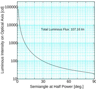
3.7 Semiangle at half power and luminous intensity on optical axis. . . 27
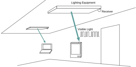
4.1 A proposed system image. . . . 30
4.2 L-PPM system. . . . 31
4.3 Symbol timing controller. . . . 32
4.4 Radiation pattern. . . . 34
4.5 Illuminance distribution at each height between the light equipment and the receiver. . . . 34
4.6 Calculation of illuminance. . . . 35
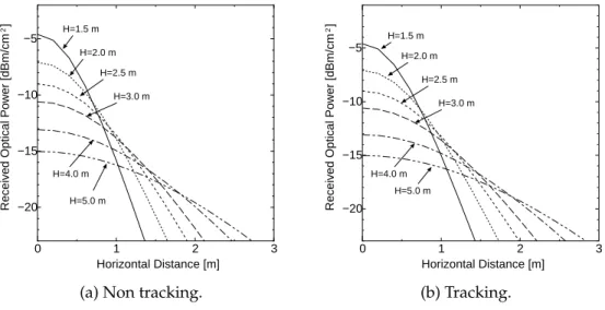
4.7 Received optical power of the general lighting. . . . 36
4.8 Received optical power of the downlight. . . . 36
4.9 Received optical power. . . . 37
4.10 Received optical power vs. electrical SNR. . . . 37
4.11 RMS delay spread at H=3.0 m. . . . 38
4.12 Mean delay time at H=3.0 m. . . . 38
iv
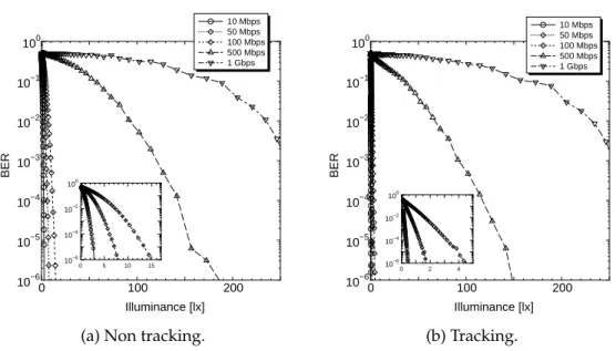
4.13 BER performance of the general lighting. . . . 39
4.14 BER performance of the downlight. . . . 39
4.15 Illuminance and BER performance of the general lighting at H=3.0 m. 40 4.16 Illuminance and BER performance of the downlight at H=3.0 m. . . 40
4.17 Influence of multiple lighting equipments. . . . 41
4.18 BER performance by plural lighting equipments at H=3.0 m. (Non tracking, FOV 90 deg.) . . . . 41
4.19 DUR and distance between lighting equipments. (Non tracking, FOV 90 deg.) . . . . 41
5.1 Proposed lighting equipment diversity system. . . . 45
5.2 Position of Lighting Equipments. . . . 46
5.3 Number of reflection. (Model A) . . . . 47
5.4 Illuminance distribution. . . . 48
5.5 The lighting equipment diversity system. . . . 49
5.6 Received optical power distribution. . . . 50
5.7 Impulse response at (0.3, 2.1, 0.85). . . . 51
5.8 RMS delay spread. . . . 52
5.9 Influence of each noise variance at corner of the room (Model A: (0.1, 0.1, 0.85)). Modulation scheme is 2-PPM. . . . 54
5.10 BER Distribution at 500 Mbit/s. . . . 55
5.11 BER Distribution at 800 Mbit/s. . . . 56
5.12 Outage Area Rate at each model. . . . 57
5.13 Position of the each lighting equipment. . . . 58
5.14 Outage area rate at each modulation scheme. . . . 59
5.15 A model of the human body as pedestrian. . . . 59
5.16 Outage call duration rate. . . . 60
5.17 Outage call duration rate vs. mean density of pedestrians: bit rate is 100 Mbit/s, and the offered load is 4 erl. . . . 61
5.18 Outage call duration rate vs. mean density of pedestrians: bit rate is 500 Mbit/s, and the offered load is 4 erl. . . . 61
5.19 Outage call duration rate vs. offered load: bit rate is 100 Mbit/s, and the mean density of pedestrians is 0.05 m
−2. . . . 62
5.20 Outage call duration rate vs. offered load: bit rate is 500 Mbit/s, and the mean density of pedestrians is 0.05 m
−2. . . . 62
5.21 Blocking rate. . . . 63
5.22 Outage call duration rate vs. offered load: bit rate is 100 Mbit/s, the mean density of pedestrian is 0.05 m
−2. . . . 64
5.23 Outage call duration rate vs. offered load: bit rate is 500 Mbit/s, the mean density of pedestrian is 0.05 m
−2. . . . 64
5.24 FIR equalizer. . . . 65
5.25 Decision feedback equalizer. . . . 66
v
5.26 Mean square error. Received optical power is -5.55 dBm/cm
2, loop
number is 1000. . . . 68
5.27 BER distribution without DFE. Data rate is 500 Mbit/s. . . . 69
5.28 BER distribution with DFE. Data rate is 500 Mbit/s. FF tap is 4, FB tap is 2, step parameter is 0.01, training sequence is 10000 bits. . . 69
5.29 BER distribution without DFE. Data rate is 800 Mbit/s. . . . 69
5.30 BER distribution with DFE. Data rate is 800 Mbit/s. FF tap is 4, FB tap is 2, step parameter is 0.01, training sequence is 10000 bits. . . 69
5.31 Outage area rate versus data rate. Step parameter is 0.01, length of training sequence is 10000 bits. . . . 70
5.32 Distance between position X and Y versus BER by channel estima- tion. FF tap is 4, FB tap is 2, Step parameter is 0.01, length of training sequence is 10000 bits. . . . 70
5.33 Outage call duration rate vs. mean density of pedestrians: bit rate is 500 Mbit/s, and the offered load is 4 erl. . . . 71
5.34 Blocking rate performance at 500 Mbit/s. . . . 72
6.1 Proposed system model. . . . 77
6.2 Waveform on power line. . . . 77
6.3 Snap-shot of generated noise waveforms. . . . 79
6.4 Integrated OFDM-QPSK System. . . . 80
6.5 Maximum relative voltage change. Data rate is 27.3 kbit/s (1 carrier), 54.6 kbit/s (2 carriers), 109.2 kbit/s (4 carriers) and 218.4 kbit/s (8 carriers). . . . 81
6.6 The BER performance of the proposed integrated system. . . . 82
6.7 BER of whole system vs. number of carrier. SNR
plis 16 dB. Data rate is 27.3 kbit/s (1 carrier), 54.6 kbit/s (2 carriers), 109.2 kbit/s (4 carriers) and 218.4 kbit/s (8 carriers). . . . 82
6.8 Numerical analysis condition. . . . 83 6.9 Horizontal distance vs. SNR
vl. Data rate is 27.3 kbit/s (1 carrier), 54.6
kbit/s (2 carriers), 109.2 kbit/s (4 carriers) and 218.4 kbit/s (8 carriers). 84
vi
List of Tables
1.1 Comparison between radio, infrared, and visible light system for
indoor wireless communication. . . . 5
1.2 Signaling rate and pulse duration specifications of IrDA 1.4. . . . . 7
3.1 Results of measurements. . . . 26
3.2 Semiangle at half power and luminous intensity on optical axis. . . 27
4.1 Design parameters of LED lighting equipments. . . . 31
4.2 SNR calculation parameters. . . . 35
5.1 Three typical models of visible light wireless environment. . . . 45
5.2 Simulation parameters. . . . 53
5.3 Simulation conditions for influence of shadowing. . . . 60
6.1 Noise parameters on power line. . . . 79
6.2 Simulation parameter for the integrated system. . . . 80
6.3 Parameters for SNR calculation. . . . 83
vii
Abstract
In 1990’s, white LEDs (Light Emitting Diodes) have been invented for various uses and subsequently investigated. Compared with conventional lighting devices, the white LED has lower power consumption, lower voltage, longer lifetime, smaller size, faster response, and cooler operation. The white LED will eventually replace incandescent or fluorescent lights in offices and homes.
In this dissertation, an indoor visible light wireless communication system uti- lizing white LED lighting equipment is proposed. In this system, these devices are used not only for illuminating rooms but also for a wireless optical commu- nication system. This dual function of LED, for lighting and communication, is creating many new and interesting applications. The function is based on the fast switching of LEDs and the modulation of the visible light waves for free-space communications. The system has large power compared with infrared wireless communication system. Based on lighting engineering, their communication per- formances are evaluated.
Then, various new communication schemes in indoor visible light environment are proposed and discussed. A diversity technique is proposed so that shadowing problem may be alleviated. Moreover, to overcome the intersymbol interference caused by optical path difference between lighting equipments, an adaptive equal- izer is proposed and discussed. The effectual interval of training sequence for channel estimation alleviates the influence of shadowing.
Finally, an integrated system of visible light wireless communication and power line communication for improvement of convenience and user friendliness is pro- posed. This system can also be considered as a very economical integration be- tween power line communication and wireless communication. In this system, there is no necessity to lay a new communication cable in a ceiling. And, by screwing the electric bulb into a socket, the data transmission becomes possible.
From these proposals, it is found that the idea of the proposed systems is very
promising for future high speed wireless networks and the visible light wireless
communication can be one choice for an indoor optical wireless data transmission
system.
Chapter 1
General Introduction
Visible light wireless communication is the communication technology using “Vis- ible Light”; the visible light everywhere around our daily life. We are heavily relying on our eyes to gather almost all information for our day-to-day activities.
Visible light has an impact on virtually every phase of human experience, since we perceive the world largely through vision. Evolution of human being, human life, observation of natural phenomena such as rainbows and sunsets, and recognition of objects about us—all involve the visible light. Therefore “Visibility” is one of the most important things for human being, and many devices are developed to assist our “Visibility”. For instance, there are many devices including the lightings in our offices, home, the lightings on roads, commercial displays, small lamps on electronic home appliances including TVs, etc. Recently, the visible light wire- less communication, which adds the secondary function of data transmission to these infrastructure devices, has been receiving increasing attention in consumer communication.
1.1 Historical Overview of Visible Light Wireless Com- munication
One of the first visible light wireless communication systems was reported by Alexander Graham Bell. In 1880, he transmitted the wireless telephone message on his newly invented “photophone” [1.1]. The device allowed for the transmission of sound on a beam of visible sunlight. Bell’s photophone worked by projecting voice through an instrument toward a mirror. Vibrations in the voice caused similar vibrations in the mirror. Bell directed sunlight into the mirror, which captured and projected the mirror’s vibrations. The vibrations were transformed back into sound by a sensitive selenium crystal (Fig. 1.1). Although communication over several hundreds of meters was proved, the evolution of visible light wireless communication had to wait until more appropriate devices had been developed.
Meanwhile, primitive signaling systems with flashing lamps, based on Morse
CHAPTER 1. GENERAL INTRODUCTION 3
(a) Transmitter. (b) Receiver.
Figure 1.1: Photophone. (Lucent Technologies, Bell Labs Innovations)
transmission with the human eye as the detector, were widely used, e.g. for exchanging messages between ships.
In 1990’s, white LEDs (Light Emitting Diodes) have been invented for vari- ous uses and subsequently investigated. However, it was impossible to obtain white LED until 1990’s due to the lack of highly efficient blue and green LED.
InGaN-based highly efficient blue LED and GaP-based green LED have now be- come commercially available. Using these LEDs, it is possible to fabricate white LEDs by mixing the three primary colors (red, green, and blue). Compared with conventional lighting devices, the white LED has lower power consumption, lower voltage, longer lifetime, smaller size, faster response, and cooler operation. As a result of these developments, much of the growth for LEDs will be concentrated in three main areas: The first is in automotive applications and traffic control devices such as head lights, tail lights, road lightings, and traffic signals. The second is in variable message signs such as the one located at Times Square of New York which displays commodities, news and other information. The third concentration would be in standard lighting sources such as architectural lighting, aerospace and automotive interior lighting, exit signs and emergency lighting, flashlights, and so on.
In 1999 to 2001, traffic information systems using modulated LED traffic sig-
nal have been proposed [1.2–1.4]. In these systems, the function is based on the
fast switching of LEDs and the modulation of the visible light waves for outdoor
free space communication. In 2000’s, visible light wireless communication utiliz-
ing white LED lightings for indoor wireless networks have been proposed by a
group including the author [1.5–1.9]. Owing to the function of lighting, the system
has large power in comparison with indoor wireless LAN (Local Area Network)
systems including infrared, and wide radiation pattern at transmitter. As just
described, the peculiar characteristics and the problems in visible light wireless
communication have been discussed. By these proposals, the possibility of broad-
CHAPTER 1. GENERAL INTRODUCTION 4
band communication for consumer and the expectation to pervasive computing have been suggested. Visible light wireless communication has been consequently brought to public attention.
1.2 Difference between Visible Light Wireless Com- munication and Other Wireless Communications
In indoor wireless communication, optical radiation offers several significant ad- vantages over radio. Optical emitters and detectors capable of high speed op- eration are available at low cost. The optical spectral region offers a virtually unlimited band width that is unregulated worldwide. It may not provide the bio- logical damages to humans by the electromagnetic. Since no malfunction such as aircraft equipment and medical instruments is anticipated, it enables the optical wireless communication in airports and hospitals where radio wireless commu- nication cannot be used according to electromagnetic wave interference. Infrared and visible light are close together in wavelength, and they exhibit qualitatively similar behavior. Both are absorbed by dark objects, diffusely reflected by light colored objects, and directionally reflected from shiny surfaces. Both types of light penetrate through glass, but not through walls ore other opaque barriers, so that optical transmissions are confined to the room in which they originate. This signal confinement makes it easy to secure transmissions against casual eavesdropping, and it prevents interference between links operating in different rooms. Thus, optical wireless LAN’s can potentially achieve a very high aggregate capacity, and their design may be simplified, since transmissions in different rooms need not be coordinated. When an optical link employs intensity modulation with direct detection (IM/DD), the short carrier wavelength and large area, square law detec- tor lead to efficient spatial diversity that prevents multipath fading. By contrast, radio links are typically subject to large fluctuations in received signal magnitude and phase. Freedom form multipath fading greatly simplifies the design of optical links [1.10].
The optical medium is not without drawbacks, however. Because optical cannot penetrate walls, communication from one room to another requires the installation of infrared access points that are interconnected via a wired backbone. In many indoor environments there exists intense ambient noise, arising from sunlight, incandescent lighting and fluorescent lighting, which induce noise in an optical receiver.
Infrared wireless communication has an eye safety problem in conjunction with
the possible dangerous high energy density due to its invisibility. Therefore, the
higher data rate transmission is not easy through infrared wireless communica-
tion. As compared to infrared wireless communication, the visible light wireless
communication is suitable to human eyes in terms of “Visibility”. The system
CHAPTER 1. GENERAL INTRODUCTION 5
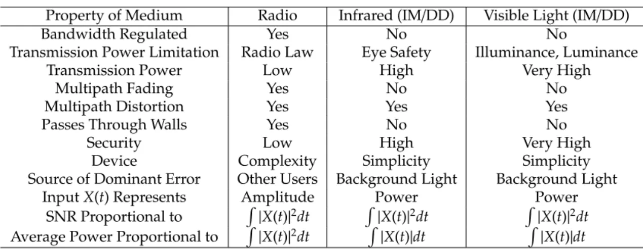
Table 1.1: Comparison between radio, infrared, and visible light system for indoor wireless communication.
Property of Medium Radio Infrared (IM/DD) Visible Light (IM/DD)
Bandwidth Regulated Yes No No
Transmission Power Limitation Radio Law Eye Safety Illuminance, Luminance
Transmission Power Low High Very High
Multipath Fading Yes No No
Multipath Distortion Yes Yes Yes
Passes Through Walls Yes No No
Security Low High Very High
Device Complexity Simplicity Simplicity
Source of Dominant Error Other Users Background Light Background Light
InputX(t) Represents Amplitude Power Power
SNR Proportional to R
|X(t)|2dt R
|X(t)|2dt R
|X(t)|2dt Average Power Proportional to R
|X(t)|2dt R
|X(t)|dt R
|X(t)|dt
employs visible LED, which can be transmitted by a few watts, a relatively high energy for the use of lighting. This means that the visible light communication is capable to transmit data by the higher data rate. And visible light communication has infrastructure. Many devices are developed to assist our “Visibility”. There are many devices including the lightings in our offices, home, the lightings on roads, traffic signals, commercial displays, small lamps on electronic home appliances in- cluding TVs, etc. Therefore, in visible light wireless communication, these devices can use as assist of visibility and communication device. Moreover, because of the visibility, user can recognize lighting area as communication service area. Thus, visible light communication is very suitable to the environment which requires human interface.
The characteristics of radio, infrared, visible light indoor wireless links are compared in Table 1.1.
1.3 Conventional Optical Wireless Communication Sys- tems
There is a growing interest in indoor wireless networks as a consequence of the
large-scale utilization of personal computers and mobile communicators. In this
applications, an optical wireless communication system is a candidate for the me-
dia of wireless networks. Infrared is preferred as wavelength in these applications,
originally. This is because essentially a large total transmission bandwidth is possi-
ble, facilitating fast transmission systems due to the very high frequency involved
in optical carrier. Moreover, because of the short wavelength, optical radiation is
confined within a room since the radiation is either reflected or absorbed by the
CHAPTER 1. GENERAL INTRODUCTION 6
Printer
PC IrDA Link
Mobile Phone
Figure 1.2: An example of an IrDA.
IrPHY 1.0 2400 to 115,200 b/s
IrPHY 1.1 1.152 and 4 Mb/s IrDA Link Access Protocol (IrLAP)
IrLMP Multiplexer (LM-MUX) Tiny TP
IrOBEX IrLAN IrCOMM
IrLMP Information Access
Service (LM-IAS)
Applications
Figure 1.3: The IrDA protocol stack.
walls. Therefore cell planning in networks is simple.
1.3.1 IrDA links
The infrared data association (IrDA) was established in 1993 as a collaboration between major industrial organizations in order to establish an open standard for infrared data communication [1.11–1.16]. The resulting IrDA protocol was aimed to provide a simple, low-cost, reliable means of infrared communication between devices such as portable computers, desktop computers, printers, other periph- erals, and LANs using directed point-to-point connectivity. Figure 1.2 illustrates an example image of an IrDA link with which PC peripherals are connected to a PC. IrDA links can currently provide a baud rate up to 115.2 kbit/s, or 16 Mbit/s with a high-speed extension, using half-duplex point-to-point connectivity. The IrDA protocol stack is shown in Fig. 1.3. The IrDA protocol stack consists of three mandatory layers: the physical (IrPHY) layer, the IrLAP layer, and the IrDA Link Management Protocol (IrLMP) layer.
The IrDA physical layer provides half-duplex point-to-point communication
through the infrared medium and provides services to the upper IrLAP layer. The
infrared medium interface specification requires a maximum link distance of at
least 1 m and a half angle range of 15 to 30 degrees. This configuration is shown in
Fig. 1.4. infrared transmitters have to conform to eye safety limitations on power
output [1.17]. The maximum output intensity is specified at 500 mW/sr. Typical
output power of transmitters is in tens of milliwatts range. In an IrDA link, nearly
visible light (850 to 950 nm) is used. Version 1.0 of the physical layer provided a data
rate of up to 115.2 kbit/s using a connection to the standard universal asynchronous
receiver transceiver (UART) of the IrDA device. The hardware typically consists
of an infrared transceiver module containing infrared LED with output driver and
CHAPTER 1. GENERAL INTRODUCTION 7
0 to 1 m Half Angle 15 to 30 degs.
Optical Interface Port
Figure 1.4: IrDA optical geometry.
Table 1.2: Signaling rate and pulse duration specifications of IrDA 1.4.
Signaling Rate Modulation Pulse Duration Pulse Duration Pulse Duration
Minimum Nominal Maximum
2.4 kbit/s RZI 1.41 ms 78.13 ms 88.55 ms
9.6 kbit/s RZI 1.41 ms 19.53 ms 22.13 ms
19.2 kbit/s RZI 1.41 ms 9.77 ms 11.07 ms
38.4 kbit/s RZI 1.41 ms 4.88 ms 5.96 ms
57.6 kbit/s RZI 1.41 ms 3.26 ms 4.34 ms
115.2 kbit/s RZI 1.41 ms 1.63 ms 2.23 ms
0.576 Mbit/s RZI 295.2 ns 434.0 ns 520.8 ns
1.152 Mbit/s RZI 147.6 ns 217.0 ns 260.4 ns
4.0 Mbit/s
(single pulse) 4PPM 115.0 ns 125.0 ns 135.0 ns
(double pulse) 4PPM 240.0 ns 250.0 ns 260.0 ns
16.0 Mbit/s HHH(1,13)1 38.3 ns 41.7 ns 45.0 ns
infrared detector and receiver, and encoding/decoding circuitry. This can be as a plug-in adapter to the portable computers. The modulation scheme is return-to- zero (RZ) with a 3/16 bit time pulse duration. Version 1.1 extends the specification to support data rates of 1.152 Mbit/s and 4 Mbit/s. The 1.152 Mbit/s system uses return-to-zero (RZ) modulation scheme as in version 1.0 of the specification, but 4 Mbit/s system requires additional hardware for a 4-pulse position modulation (PPM) scheme and phase-locked loop (PLL) detection. Version 1.4 of IrDA standard will be published in 2001. This version supports data rates of 16 Mbit/s with low duty cycle, rate 2/3, and (d, k)
=(1, 13) run-length limited (RLL) code [1.18]. The modulation scheme in version 1.4 is summarized in Table 1.2.
1HHH(1.13) modulation is a newly coding which is utilized low duty cycle, rate 2/3, and (d, k)
=(1, 13) run-length limited (RLL) code.
CHAPTER 1. GENERAL INTRODUCTION 8
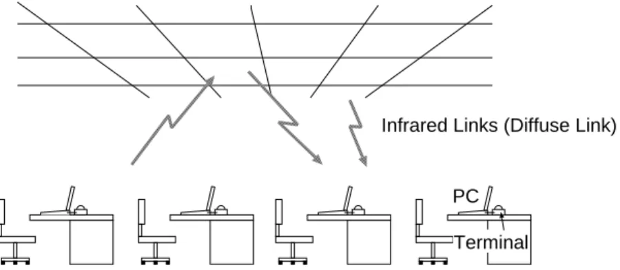
PC Terminal
Infrared Links (Diffuse Link)
Figure 1.5: An example of an IEEE 802.11 network with infrared transmission.
1.3.2 Physical layer for IEEE 802.11
IEEE 802.11 standard for wireless LANs defines a specification for an infrared phys- ical layer [1.19, 1.20]. In the United States, the executive committee of the IEEE 802 project created the IEEE 802.11 group to work on the specification of a wireless LAN for different technologies, including radio and infrared. The standard was approved in June 1997. An essential characteristic of the IEEE 802.11 specification is that there is a single medium access control (MAC) sub-layer common to all physical (PHY) layers. This feature will allow easier interoperability among the many physical layers that are expected to be defined in the future, driven by the fast technological progress in this field. There are presently three different PHY layers in the standard: infrared, frequency hopping spread-spectrum (FHSS), and direct sequence spread-spectrum (DSSS). Infrared and radio can be considered complementary technologies for the support of wireless LANs. Infrared technol- ogy is well suited for low-cost low-range applications, such as ad hoc networks. In this layers of the IEEE 802.11 standard, nearly visible light (850 to 950 nm) is used.
Figure 1.5 illustrates an example image of an IEEE 802.11 network with infrared transmission.
The infrared PHY layer supports two data rates: 1 and 2 Mbit/s. The specifica- tion of two data rates is aimed at following:
•
A smooth migration to higher data rates
•
Asymmetric operation of the basic service set (BSS)
PPM scheme is utilized in the IEEE 802.11 standard, basically. There is a different PPM scheme for each data rate: 16-PPM for 1 Mbit/s and 4-PPM for 2 Mbit/s. The purpose of this feature is to ensure that the basic pulse is the same at both data rates, which minimizes the additional complexity introduced by the 2 Mbit/s data rate.
The emitter and receiver circuits can be almost identical (in particular, the same
front-end can be used at both data rates), and the most significant enhancements
CHAPTER 1. GENERAL INTRODUCTION 9
4 bits @ 1 Mbit/s
1 symbol 16-PPM
8 bits @ 2 Mbit/s
4 symbol 4-PPM
4-PPM symbol 250 ns
Figure 1.6: PPM signals at 1 and 2 Mbit/s.
are required on the synchronization circuits. The PPM signals at 1 and 2 Mbit/s are represented in Fig. 1.6. The duration of each pulse is 250 ns, and the peak optical power is 2 W. Therefore, the average optical power is 250 mW at 2 Mbit/s and 125 mW at 1 Mbit/s.
1.4 Purpose and Position of This Study
Trends in the telecommunications and computer industries suggest that the net- work of the future will consist of a high capacity backbone network with short- range communication links providing network access to portable communicators and portable computers. In this vision of the future, mobile users will access to similar grade high-speed network services available to wired terminals. For this purpose, some parts of communication links need to be constructed wireless.
During the last decade, therefore, the wireless communication technology has grown rapidly [1.21–1.25].The technology base for implementing this concept does not yet exist, however. Radio technology, although well-suited for moderate- speed applications such as voice, may not be sufficient to support many high- speed applications. To illustrate the potential capacity requirements of a wireless network, consider the needs of a portable high-quality digital display. To reduce its size, weight, battery-power consumption, and cost, it may be advantageous to make it simple as possible, having little on-board computational power, and relegating intensive signal-processing tasks such as video decompression to the transmitter platform. To accomplish this, however, it will require mid-range or short-range wireless communication links with extremely high capacity. In an extreme case, for example, uncompressed high-definition video can require a data rate of 1 Gbit/s or more. More realistically, data rates over 100 Mbit/s may be adequate for practical applications.
Moreover, radio wave transmission technology suffers from electro-magnetic
CHAPTER 1. GENERAL INTRODUCTION 10
interference (EMI) problems as the radio spectrum gets increasingly crowded.
Now that personal communicators and wireless computer networks are evolving rapidly, the available spectrum is considered to be a scarce resource. Simulta- neously, there is an increase in the interference level caused by switched power supplies and other high-frequency equipment. Particularly in hospitals and indus- trial environments, the applicability of radio systems is already seriously limited by these problems. Extensive frequency allocation regulations can only partly solve them. Although eventually EMI aspects will become an integral part of ev- ery system design, future applications require the exploration of new wavelength ranges.
An optical wireless communication system is an attractive alternative to radio, primarily because of a virtually unlimited, unregulated bandwidth [1.26–1.28]. The optical spectrum is a universally available resource without frequency and wave- length regulations. An optical wireless communication system has the advantage of requiring low-cost and low-power consumption components, also [1.29]. More- over, for indoor applications, optical radiation is confined within a room since the radiation is either reflected or absorbed by the walls because of its short wave- length. Therefore cell planning in networks is simple and easy. In the near future, optical wireless communication system will be an attractive candidate for wireless access network.
As earlier mentioned, visible light wireless communication will be a powerful candidate for future indoor high speed optical wireless communication systems, such as more than hundreds Mbit/s transmission speed, to support real multime- dia transmissions. In this dissertation, indoor visible light wireless communication systems utilizing white LED lightings will be proposed, and the peculiar charac- teristics and the problems will be discussed. Moreover, some adaptation schemes will be proposed in visible light wireless environment. Through this dissertation, the potentiality of visible light wireless communication technology for the future indoor wireless system will be shown.
The relationship between the previous researches of visible light wireless com- munication system and this dissertation is summarized in Fig. 1.7.
1.4.1 Outline of the Dissertation
This dissertation is organized as follows. Chapter 1 which is the present chapter
has introduced the overview of visible light wireless communication systems and
described the motivations of this research. In chapter 2, basic knowledge for indoor
optical wireless communication systems has introduced. Some numerical analyses
and computer simulations are introduced. In the following chapter 3, basic white
LED characteristics by measurements has shown. In chapter 4, indoor visible light
data transmission system with white LED lighting equipment is proposed and
discussed. Based on lighting engineering, their communication performance is
CHAPTER 1. GENERAL INTRODUCTION 11
Requirement of wide band communication in indoor wireless networks Dissemination of white LED
Proposal of Indoor Visible Light Wireless Communication Systems utilizing White LED Lighting Equipment
Their performance evaluation based on lighting engineering Chapter 4
Chapter 2
Basic Knowledge for Indoor Optical Wireless Communication Chapter 3
Characteristics of White LED
Chapter 5
Proposal of Diversity Scheme utilizing Plural White LED Lighting Equipments in Visible Light Wireless Communication
Basic study of the communication performance Tolerance to shadowing
Mitigation of ISI by adaptive equalization
Chapter 6
Integrated System of Visible Light Wireless Communication and Power Line Communication
Easy wiring in ceiling for visible light wireless communication Expectation of dissemination
For high-speed communication
For convenience and user-friendliness
Figure 1.7: Outline of the dissertation.
REFERENCES 12
evaluated. In chapter 5, various new schemes in indoor visible light environment are proposed and discussed. In this chapter, diversity technique is proposed so that shadowing problem may be alleviated and the availability of the system is shown. Moreover, to overcome the intersymbol interference caused by optical path difference between lighting equipments, adaptive equalizer is proposed and discussed. In chapter 6, integrated system of visible light wireless communication and power line communication for improvement of convenience and user friend- liness is proposed. Finally, this dissertation is concluded in chapter 7 and future issues are described.
1.5 References
[1.1] A. G. Bell, “On the Production and Reproduction of Sound By Light,” American Journal of Sciences, Third Series, vol. XX, no. 118, pp. 305–324, 1880.
[1.2] G. Pang, T. Kwan, H. Liu, Chi-Ho. Chan, “Optical Wireless based on High Brightness Visible LEDs,” IEEE Conference of Industry Applications, vol. 3, pp. 1693–1699, 1999.
[1.3] G. Pang, T. Kwan, Chi-Ho. Chan, “LED Wireless,” IEEE Industry Applications Magazine, vol. 8, issue 1, pp. 21–28, 2002.
[1.4] M. Akanegawa, Y. Tanaka, M. Nakagawa, “Basic Study on Traffic Information Sys- tem using LED Traffic Lights,” IEEE Transactions on Intelligent Transportation Sys- tems, vol. 2, issue 4, pp. 197–203, 2001.
[1.5] Y. Tanaka, S. Haruyama, M. Nakagawa, “Wireless Optical Transmissions with White Colored LED for Wireless Home Links,” IEEE International Symposium on Personal, Indoor and Mobile Radio Communications, vol. 2, pp. 1325–1329, 2000.
[1.6] T. Komine, Y. Tanaka, S. Haruyama, M. Nakagawa, “Basic Study on Visible-Light Communication using Light Emitting Diode Illumination,” International Sympo- sium on Microwave and Optical Technology, pp. 45–48, 2001.
[1.7] Y. Tanaka, T. Komine, S. Haruyama, M. Nakagawa, “A Basic study of optical OFDM system for Indoor Visible Communication utilizing Plural White LEDs as Lighting,”
International Symposium on Microwave and Optical Technology, pp. 303–306, 2001.
[1.8] T. Komine, M. Nakagawa, “Integrated System of White LED Visible-Light Commu- nication and Power-Line Communication,” IEEE Transactions on Consumer Elec- tronics, vol. 49, no. 1, pp. 71–79, 2003.
[1.9] Y. Tanaka, T. Komine, S. Haruyama, M. Nakagawa, “Indoor Visible Light Data Transmission System utilizing White LED Lights,” IEICE Transactions on Commu- nications, vol. E86–B, no. 8, pp. 2440–2454, 2003.
[1.10] J. M. Kahn, J. R. Barry, “Wireless Infrared Communications,” Proceedings of the IEEE, vol. 85, no. 2, pp. 265–298, 1997.
REFERENCES 13
[1.11] P. Barker, A. C. Boucouvalas, “Performance modeling of the IrDA protocol for in- frared wireless communications,” IEEE Communications Magazine, vol. 36, no. 12, pp. 113–117, 1998.
[1.12] Infrared Data Association, Walnut Creek, CA, “Infrared Data Association Serial Infrared Link Access Protocol (IrLAP), version 1.1,” 1996.
[1.13] Infrared Data Association, Walnut Creek, CA, “Infrared Data Association Link Man- agement Protocol (IrLMP), version 1.1,” 1996.
[1.14] Infrared Data Association, Walnut Creek, CA, “Infrared Data Association Link Ac- cess Protocol Specification for 16 Mb/s Addition (VFIR), Errata to IrLAP version 1.1,” 1999.
[1.15] Infrared Data Association, Walnut Creek, CA, “Infrared Data Association Serial Infrared Physical Layer Link Specification for 16 Mb/s Addition (VFIR), Errata to IrPHY version 1.3,” 1999.
[1.16] Infrared Data Association, “http://www.irda.org/”.
[1.17] International Electrotechnical Commission, Geneva, Switzerland, “IEC 60825-1:
Safety of Laser Products,” 1998.
[1.18] Infrared Data Association, Walnut Creek, CA, “Infrared Data Association Serial Infrared Physical Layer Specification, version 1.4,” 2001.
[1.19] IEEE 802 LAN/MAN Standards Committee, “http://www.ieee802.org/”.
[1.20] R. T. Valadas, A. R. Tavares, A. M. de Oliveira Duarte, “The infrared physical layer of the IEEE 802.11 standard for wireless local area networks,” IEEE Communications Magazine, vol. 36, no. 12, pp. 107–112, 1998.
[1.21] J. E. Padgett, C. G. G ¨unther, T. Hattori, “Overview of wireless personal communi- cations,” IEEE Communications Magazine, vol. 33, no. 1, pp. 28–41, 1995.
[1.22] D. C. Cox, “Wireless personal communications : What is it?,” IEEE Personal Com- munications Magazine, vol. 2, no. 2, pp. 20–35, 1995.
[1.23] R. Pandya, “Emerging mobile and personal communication systems,” IEEE Com- munications Magazine, vol. 33, no. 6, pp. 44–52, 1995.
[1.24] R. O. LaMaire, A. Krishna, P. Bhagwat, J. Panian, “Wireless LANs and mobile networking : Standards and future directions,” IEEE Communications Magazine, vol. 34, no. 8, pp. 86–94, 1996.
[1.25] K. Pahlavan, A. Zahedi, P. Krishnamurthy, “Wideband local access : Wireless lan and wireless atm,” IEEE Communications Magazine, vol. 35, no. 11, pp. 34–40, 1997.
[1.26] J. R. Barry, “Wireless Infrared Communications,” Kluwer Academic Press, Boston, MA, 1994.
REFERENCES 14
[1.27] D. J. T. Heatley, D. R. Wisely, I. Neild, P. Cochrane, “Optical wireless: The story so far,” IEEE Communications Magazine, vol. 36, no. 12, pp. 72–82, 1998.
[1.28] R. Otte, L. P. de Jong, A. H. M. van Roermund, “Low-power Wireless Infrared Communications,” Kluwer Academic Publishers, The Netherlands, 1999.
[1.29] A. M. Steel, R. N. Stavinou, D. C. O’Brien, D. J. Edwards, “Indoor optical wireless systems – a review,” Optical and Quantum Electronics, vol. 29, no. 3, pp. 348–378, 1997.
Chapter 2
Basic Knowledge for Indoor Optical Wireless Communication
2.1 Intensity Modulation and Direct Detection Chan- nels
Modulation techniques for radio wireless systems include amplitude, phase, and frequency modulation (AM, PM, and FM), as well as some generalizations of these techniques. Radio receivers employ one or more antennas, each followed by a heterodyne of homodyne down-converter, which is comprised of a local oscillator and a mixer. Efficient operation of this mixer relies upon the fact that it receives both the carrier and the local oscillator in a common electromagnetic mode. The down-converter output is an electrical signal whose voltage is linear in the amplitude of the received carrier electric field.
In a low-cost optical wireless system, it is extremely difficult to collect appreciable signal power in a single electromagnetic mode. This spatially incoherent reception makes it difficult to construct an efficient heterodyne or homodyne down-converter for AM, PM, and FM, or to detect AM or PM by any other means. For optical wireless links, the most viable modulation is intensity modulation, in which the desired waveform is modulated onto the instantaneous power of the carrier. The most practical down-conversion technique is direct detection, in which a photo detector produces a current proportional to the received instantaneous power, i.e., proportional to the square of the received electric field.
The modeling of optical wireless channels with IM/DD is illustrated in Fig. 2.1. The transmitted waveformX(t) is the instantaneous optical power of the lightwave emitter.
The received waveformY(t) is the instantaneous current in the receiving photo detector, which is proportional to the integral over the photo detector surface of the total instanta- neous optical power at each location. The received electric field generally displays spatial variation of magnitude and phase, so that a multipath fading would be experienced if the detector were smaller that a wavelength. Fortunately, typical detector areas are millions of square wavelength, leading to spatial diversity that prevents a multipath fading. Thus when the detector is moved by a distance of the order of a wavelength, no change in the channel is observed. As the transmitted optical powerX(t) propagates along various paths
CHAPTER 2. BASIC KNOWLEDGE FOR OPTICAL WIRELESS 16
Optical Power X(t)
Channel Impulse Response
h(t)
Photo Diode R
Signal-independent Noise N(t)
Photocurrent Y(t)
Figure 2.1: Modeling link as a baseband filter, time-invariant system having impulse responseh(t), with signal-independent, additive noiseN(t). The photode- tector has responsivityR.
of different lengths, optical wireless channels are still subject to multipath distortion. The channel can be modeled as a baseband linear system, with instantaneous input powerX(t), output currentY(t), and an impulse responseh(t), as shown in Fig. 2.1. Alternately, the channel can be described in terms of the frequency response [2.1]
H(f)= Z ∞
−∞
h(t)e−j2πf tdt, (2.1) where is the Fourier transform ofh(t). It is usually appropriate to model the channel “h(t)⇔ H(f)” as fixed, since it usually changes only when the transmitter, receiver, or objects in the room are moved by tens of centimeters. The linear relationship betweenX(t) andY(t) is a consequence of the fact that the received signal consists of many electromagnetic modes.
By contrast, we note that when IM/DD is employed in dispersive single-mode optical fiber, the relationship betweenX(t) andY(t) is sometimes nonlinear.
In many applications, optical wireless links are operated in the presence of intense infrared and visible background light. While received background light can be minimized by optical filtering, it still adds shot noise, which is usually the limiting noise source in a well-designed receiver. The desired signals contain a time-varying shot-noise process which has an average rate of 104of 105photons/bit. In the channel model, however, intense ambient light striking the detector leads to a steady shot noise having a rate of order of 107 to 108 photons/bit, even if a receiver employs a narrow-band optical filter. However, we neglect the shot noise caused by signals and model the ambient-induced shot noise as a Gaussian process. When little of no ambient light is present, the dominant noise source is receiver pre-amplifier noise, which is also signal-independent and Gaussian (though often non-white). Thus we usually model the noiseN(t) as Gaussian and signal-independent.
This stands in contrast to the signal-independent, Poisson noise considered in photon- counting channel models. Fluorescent lamps emit infrared that is modulated in nearly periodic fashion; when present, this adds a cyclostationary component toN(t) [2.2, 2.3].
The baseband channel model is summarized by
Y(t)=RX(t)⊗h(t)+N(t), (2.2) where the “⊗” symbol denotes convolution and R is the detector responsivity (A/W).
While Eq. (2.2) is simply a conventional linear filter channel with additive noise, optical
CHAPTER 2. BASIC KNOWLEDGE FOR OPTICAL WIRELESS 17
wireless systems differ from conventional electrical or radio systems in several respects.
Because the channel inputX(t) represents instantaneous optical power, the channel input is non-negative:
X(t)≥0, (2.3)
and the average transmitted optical powerPtis given by Pt= lim
T→∞
1 2T
Z T
−T
X(t)dt, (2.4)
rather than the usual time-average of|X(t)|2, which is appropriate whenX(t) represents amplitude. The average received optical power is given by
Pr=H(0)Pt, (2.5)
where the channel DC gain isH(0)=R∞
−∞h(t)dt. The performance of a wireless optical link at bit rateRbis related to the received electrical SNR
SNR= R2P2
RbN0 = R2H2(0)R2t
RbN0 , (2.6)
assuming thatN(t) is dominated by a Gaussian component having double-sided power- spectral densityN0. From Eq. (2.6), we see that the SNR depends on the square of the received optical average power, implying that IM/DD optical wireless links must transmit at a relatively high power and can tolerate only a limited path loss. This stands in contrast to the case of radio wave channels, where the SNR is proportional to the first power of the received average power.
2.2 Channel Direct Current Gains
The frequency responses of optical channels are relatively flat near direct current (DC), so for most purposes, the signal most important quantity characterizing a channel is the DC gainH(0), which relates the transmitted and received average powers via Eq. (2.5). In this subsection we compute the DC gains of line of sight (LOS) link.
In LOS links, the DC gain can be computed fairly accurately by considering only the LOS propagation path. We consider the link geometry shown in Fig. 2.2. Suppose the transmitter emits an axially symmetric radiation pattern described by the radiant intensity (W/sr)PtR0(φ). Here,R0(φ) is normalized so that 2πRπ
0 R0(φ) sinφdφ=1. At the receiver, located at distancedand angleφwith respect to the transmitter, the irradiance (W/cm2) is Is(d, φ)=PtR0(φ)/d2. The received power is
Pr =
( Is(d, φ)ATs(ψ)g(ψ) cosψ, 0≤ψ≤Ψc
0, ψ >Ψc. (2.7)
whereTs(ψ) is the signal transmission of the filter,g(ψ) is the concentrator gain andΨcis the concentrator FOV (semiangle).Ts(ψ) may represent an average over the filter transmission at different wavelengths (if the source spectrum is not narrow) and/or angles of incidence
CHAPTER 2. BASIC KNOWLEDGE FOR OPTICAL WIRELESS 18
!#"#
$ %
&"#'()*
+$-,
.0/21
.03#1
PSfrag replacements
φ ψ Φ1/2Figure 2.2: Calculation for channel DC gain.
upon the filter (if different rays strike the filter at different angles of incidence). In this dissertation, for simplicity, we assumeTs(ψ)=1 and g(ψ)=1. We obtain the channel DC gain:
H(0) =
A
d2R0(φ)Ts(ψ)g(ψ)cosψ, 0≤ψ≤Ψc
0, ψ >Ψc.
(2.8)
which we observe is proportional tod−2. From Eq. (2.11), we observe that ifdandR0(φ) are fixed, the most effective means to increaseH(0) are to increase the detector areaA.
The emission from a variety of practical LOS transmitters can be modeled reasonably using a generalized Lambertian radiant intensity [2.4]
R0(φ)= m+1
2π cosm(φ). (2.9)
The ordermis related toΨc, the transmitter semiagnel at half power, by m=− ln 2
ln(cosΦ1/2). (2.10)
The channel DC gain is given by
H(0) =
(m+1)A
2πd2 cosmφTs(ψ)g(ψ)cosψ, 0≤ψ≤Ψc
0, ψ >Ψc.
(2.11)
CHAPTER 2. BASIC KNOWLEDGE FOR OPTICAL WIRELESS 19
2.3 Electrical SNR and BER
In this section we compute the electrical SNR at receiver and BER. Each sample of the receiver output contains a Gaussian noise having a total variance (A2) that is the sum of contributions from shot and thermal noises
σtotal=σshot+σthermal. (2.12)
The electrical SNR is expressed as
SNR= (RPr)2
σ2total , (2.13)
where received optical power is given by
Pr=H(0)Pt. (2.14)
And the BER is given by
OOK:BER=Q(√
SNR), (2.15)
L−PPM:BER=Q(
r1
2Llog2L√
SNR), (2.16)
where
Q(x)= 1 p(2π)
Z ∞
x
e−y2/2dy. (2.17)
For example, to achieve BER=10−6it requires SNR=13.6 dB in OOK and 2-PPM. The shot noise variance is given by
σshot =2qRPrB+2qIbgI2B, (2.18) whereqis the electronic charge,Bis equivalent noise bandwidth,Ibgis background current.
I2, noise bandwidth factor, is set to 0.562. At OOK, noise bandwidthBis equivalent to data rateRb. And at 2-PPM,Bis equivalent to 2Rb.
Among pre-amplifier designs, the transimpedance type is best suited to most optical link applications, because its achieves a large dynamic range and a wide bandwidth without the need for equalization [2.5]. Under typical conditions, lower noise is achieved if the front-end device is a field-effect transistor (FET), rather than a bipolar-junction transistor (BJT) [2.5, 2.6]. If power consumption is constrained, however, a BJT may achieve superior results. We follow the analysis of Smith and Personick in computing the receiver noise [2.5, 2.7]. We assume the use of p-i-n photodetectors in conjunction with FET-base transimpedance pre-amplifiers. We neglect FET gate leakage and 1/f noise. The thermal noise variance is given by
σthermal= 4kTk
RF I2B+16π2kTkΓ
gm (Cd+Cg)2I3B3. (2.19) The first term represents thermal noise from the feedback resistor;kis Boltzmann’s constant, Tk is absolute temperature, andRFis the feedback resistance. In the second term, which
REFERENCES 20
describes thermal noise from the FET channel resistance,Γis the FET channel noise factor, gm is the FET transconductance, Cd is the capacitance of a detector, Cg is the FET gate capacitance, andI3=0.0868.
In order to determine explicitly how the two noise terms in Eq. (2.19) depend on the received size, we assume that the photodetector has a fixed capacitance per unit areaη, i.e.,Cd = ηA, whereAis the detector area. For simplicity, we assume that cg Cd. we assume that the transimpedance amplifier has a limited open-loop voltage gainG. in order to minimize the noise, it is desirable to maximizeRF, but if the pre-amplifier is to achieve a 3-dB cutofffrequency equal toB, then we must impose the condition RF = G/(2πBCd).
Then Eq. (2.19) becomes
σthermal= 8πkTk
G ηAI2B2+16π2kTkΓ
gm η2A2I3B3, (2.20) We choose the following parameter values [2.8]: Tk =298 K,G=10, gm =30 mS,Γ =1.5, andη=112 pF/cm2.
2.4 References
[2.1] J. M. Kahn, J. R. Barry, “Wireless Infrared Communications,” Proceedings of the IEEE, vol. 85, no. 2, pp. 265–298, 1997.
[2.2] A. J. C. Moreira, R. T. Valadas, A. M. de Oliveira Duarte, “Optical interference produced by artificial light,” Wireless Networks, vol. 3, no. 2, pp. 131–140, 1997.
[2.3] A. J. C. Moreira, R. T. Valadas, A. M. de Oliveira Duarte, “Characterization and modelling of artificial light interference in optical wireless communication systems,”
IEEE International Symposium on Personal, Indoor and Mobile Radio Communi- cations, pp. 326–331, 1995.
[2.4] F. R. Gfeller, U. Bapst, “Wireless in-house data communication via diffuse infrared radiation,” Proceedings of the IEEE, vol. 67, no. 11, pp. 1474–1486, 1979.
[2.5] S. D. Personick, “Receiver design for digital fiber optic communications system, I and II,” Bell System Technical Journal, vol. 52, no. 6, pp. 843–886, 1973.
[2.6] T. D. Nguyen, M. S. report, University of California Berkeley, 1995.
[2.7] R. G. Smith, S. D. Personick, “Receiver design for optical fiber communication sys- tems,” in Semiconductor Devices for Optical Communication, New York: Springer -Verlag, 1980.
[2.8] R. Djahani, J. M. Kahn, “Analysis of Infrared Wireless Links Employing Multibeam Transmitters and Imaging Diversity Receivers,” IEEE Transactions on Communica- tions, vol. 48, no. 12, pp. 2077–2088, 2000.
Chapter 3
Characteristics of White LED
LED has lower power consumption, lower voltage, longer lifetime, smaller size, faster response, and cooler operation, compared with conventional lighting devices. LED is used in full color displays, traffic signals, and many other means of illumination. Now, white LED is considered as a strong candidate for the future lighting technology [3.1, 3.2].
Compared with conventional lighting methods, white LED has lower power consump- tion, lower voltage, longer lifetime, smaller size, and cooler operation. The Ministry of Economy, Trade and Industry of Japan estimates, if LED replaces half of all incandescent and fluorescent lamps currently in use, Japan could save equivalent output of six mid-size power plants, and reduce the production of greenhouse gases. A national program under- way in Japan has already suggested that white LED deserves to be considered as a general lighting technology of the 21st century owing to electric power energy consumption.
White LED is currently achieved by using two different methods. The first is by com- bining a blue 450 nm - 470 nm GaN (Gallium Nitride) LED with YAG (Yttrium Aluminum Garnet) phosphor. The blue wavelength excites the phosphor causing it to glow white.
The second method is to combine red, green, and blue LEDs in the proper proportion to achieve a white color. The former is presently the most dominant and efficient technique used. Recently, new white LEDs have become available by combining a UV (Ultra Violet) LED, 380 nm, with phosphor. In addition, by combining different phosphor types with a UV LED, other colors such as purple, orange, pink etc. can be achieved.
Generally, modulation bandwidths of white LED in typical low cost device as lighting source range from 10 kHz to tens of MHz. With the explosion of interest in visible light wireless communication using white LED, it is quite likely that white LED has wide modulation bandwidth like infrared LED for communication purpose. Recently, RC-LED (Resonant Cavity LED) have been developed. Their structures are epitaxially grown by MBE on double polished n+ GaAs substrates and emit through the substrate, which is nominally transparent at these wavelength. The active layers in the cavity are 3 or 4 strained InxGa1−xAs (x∼0.17) Quantum Wells (QWs) clad by GaAs barrier layers. The bottom mirror is a multiple quarter-wave stack of GaAs/AlAs layers, known as a Distributed Bragg Reflector (DBR). The cavity is completed by the deposition of a metal mirror on the upper surface of the multilayer structure. A key property of RC-LED of application is the ability to determine the emission angular beam profile by designing the emission wavelength of the QWs inside the cavity to be approximately 10-20 nm shorter than the
CHAPTER 3. CHARACTERISTICS OF WHITE LED 22
resonance wavelength of the cavity. Moreover the modulation bandwidth of RC-LED are achieved to approximately 500 MHz [3.3–3.5]. In [3.6], a waveform compensation by pre-emphasis circuit in electrical stage has been reported. The modulation bandwidth of output waveform from RC-LED has been enlarged from 73 MHz to 223 MHz.
In this section, we measure the basic white LED (GaN LED with YAG phosphor) characteristics, analyze the experimental parameters. As common white LED, we use the Luxeon V Portable LXHL-LW6C (LUMILEDS) on the market. And the results of numerical analysis are approximated by using the experimental parameters.
3.1 Basic Properties of LED Light
We will explain the basic properties of LED light. LED light has two basic properties, a luminous intensity and a transmitted optical power. Luminous intensity is the unit that indicates the energy flux per a solid angle, and it is related to illuminance at an illuminated surface. At this time, the energy flux is normalized with visibility. The luminous intensity is used for expressing the brightness of an LED. On the other hand, the transmitted optical power indicates the total energy radiated from an LED, and as is a parameter from the point of view of optical communication.
The luminous intensity is given as:
I= dΞ
dΩ, (3.1)
whereΞis the luminous flux, which can be given from the energy fluxΞeas:
Ξ =Km Z 780
380
V(λ)Ξe(λ)dλ, (3.2)
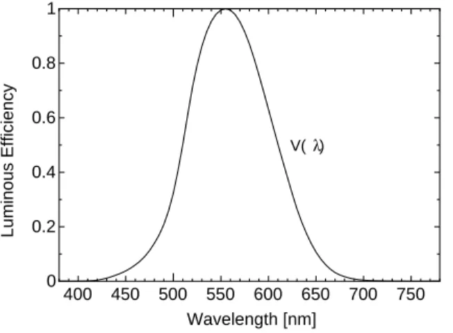
whereV(λ) is the spectral luminous efficiency as shown in Fig. 3.1,Km is the maximum visibility, and the maximum visibility is approximately 683 lm/W atλ=555 nm.
The integral of the energy fluxΞein all directions is the transmitted optical powerPt, given as:
Pt=
" Λmax
Λmin
Ξedθdλ, (3.3)
whereΛminandΛmaxare determined by the sensitivity curve of the photodiode.
3.2 Radiation Pattern
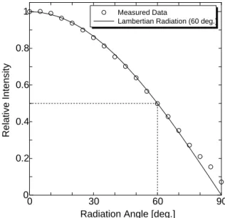
We employ a power meter (ADVANTEST: Q8230 and Q82313). And we correct the optical sensor area to 0.1 cm2. The measuring method is shown in Fig. 3.2. The input voltage of LED and input current are 6.42 V and 700 mA, respectively. And we set the junction temperature at 25 deg. C.
Figure 3.3 presents measured radiation pattern and the approximated Lambertian radiation pattern. The measured white LED of the half power semiangle is 60.0 deg.. We can know that the assumption of Lambertian radiation is correct, approximately.
CHAPTER 3. CHARACTERISTICS OF WHITE LED 23
400 450 500 550 600 650 700 750 0
0.2 0.4 0.6 0.8 1
Wavelength [nm]
Luminous Efficiency
V( )λ
Figure 3.1: Spectral luminous efficiency functions as defined by the CIE.
LED
Power Meter Figure 3.2: Measuring method of radiation pattern.
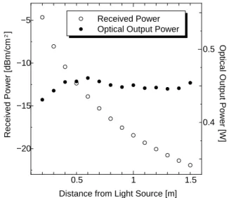
3.3 Luminous Intensity and Optical Output Power
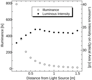
In this section, we analyze the luminous intensity and optical output from measured values. The measuring method is shown in Fig. 3.4. First, we measure the illuminance by illuminance meter in a direction toward the optical axis at 10 cm intervals. The illuminance meter is vertically set up in an optical axis. Here we set the current of electricity at 700 mA, and the junction temperature at 25 deg. C.
The illuminance expresses the brightness of an illuminated surface. The LED has a luminous intensityI(0) on optical axis and an Lambertian distribution is assumed as its light distribution. The radiant intensity depends on the angle of irradiance. Therefore, the luminous intensity in angleφis given by
I(φ)=I(0) cosm(φ). (3.4) Themis the order of Lambertian emission, which is given by the semiangle at half power of an LEDΦ1/2as
m= −ln 2
ln(cosΦ1/2). (3.5)
CHAPTER 3. CHARACTERISTICS OF WHITE LED 24
0 30 60 90
0 0.2 0.4 0.6 0.8 1
Radiation Angle [deg.]
Measured Data
Lambertian Radiation (60 deg.)
Relative Intensity
Figure 3.3: Radiation pattern.
LED
Illuminance Meter and Power Meter
10 cm 10 cm
Figure 3.4: Measuring method of optical output power and luminous intensity.
A horizontal illuminanceEis given by E= I(φ)
d2 cos(ψ), (3.6)
whereφis the angle of irradiance,ψis the angle of incidence, anddis the distance between an LED and a detector’s surface. In this section, owing to the measurement on optical axis, φis 0 deg.. Since the illuminance meter is vertically set up in the optical axis,ψis 0 deg..
Therefore, a horizontal illuminance on an optical axisEoptical axisis given by Eoptical axis = I(0)
d2 . (3.7)
From this equation, we calculate the luminous intensity.
Figure 3.5 shows measured illuminance and calculated luminous intensity on optical axis. From this figure, when the distance between light source and receivers is near, we can know that the luminous intensity is not constant. This is because the equation is true