Ball Screwボールねじ Technical descriptionボールねじ技術解説 Ball Screwボールねじ Technical descriptionボールねじ技術解説
ボールねじの構造
Construction of Ball Screws
ボールねじ技術解説 Ball Screw Technical Description
ボールねじの特長
Feature of Ball Screws
●高い機械効率
KSSボールねじは、ねじ軸とナットの間に鋼球を挿入した 転がり接触をしていますので、90%以上の高い機械効率を もっており、従来の送りねじと比較して所要トルクは1/3 以下になります。また直線運動を回転運動に変換(逆作動)
することも容易にできます(図 A-81)。
●リターンプレート式 Return-plate system
リターンプレート式は、ナット内部に設けられたコイルタイプのデフレク タによって鋼球が拾い上げられて、リターンプレートの溝に沿って循環し ます。リターンチューブ式と比較してナットの外径を小さくできるメリッ トがあります。構造上リターンプレートの部分が上になるように装置に取 付ければ、より円滑な回転が得られます。
The Return-plate system uses coil-type deflectors incorporated inside the Nut to pick up the steel Balls and circulate them via the Return-plate channel. This system has the advantage of allowing the use of a Nut that is smaller in diameter than those employed in Return-tube systems. In addition, the upward-angle installation of the Return-plate ensures even smoother rotation.
●エンドキャップ式 End-cap system
エンドキャップ式は、鋼球がねじ軸とナットの溝間を転がりながら進み、
ナット両端に取付けた循環部品(エンドキャップ)に設けた通路からナット に設けた貫通穴を通って、もとに戻る循環方式です。
The End-cap system is a recirculating system in which the Balls advance by rolling through the screw groove between the Nut and the Screw Shaft. The Balls are then returned via the holes in the Nut and the channels in the recirculating sections of the End-caps on either end of the Nut.
●リターンチューブ式 Return-tube system
ねじ軸とナットの間を転動している鋼球が、ナットに挿入したリターン チューブの先端によってねじ溝から取り出され、チューブの中を通って再 びねじ溝に戻る循環方式です。
In the Return-tube system, Balls rolling between the Nut and Shaft are picked up from the screw groove by the end of the Return-tube built into the Nut. Then, they flow back through the Return-tube to the screw groove.
●こま式 Internal-deflector system
こま式は、可能な限りナット外径、及びナット長さをコンパクトにした軽量 なミニチュアボールねじです。ねじ軸及びナットに設けられたボール転動 溝を、鋼球が軸方向荷重を受けながら転がり運動をし、ナット内部に埋め込 まれたこまの溝に沿って隣の転動溝へ移り、再び負荷領域へ戻り、無限転が り運動をします。
The Internal-deflector system employs a lightweight Miniature Ball Screw, which enables the Nut diameter and length to be reduced to the smallest possible size. The Balls bear the load while rolling along the screw groove between the Shaft and the Nut. The Balls are continuously circulated, transferred to the adjacent groove in the screw via the Internal-deflector channel and then back to the loaded groove area.
●エンドデフレクタ式 End-deflector system
ナット内部または、外部に設けたエンドデフレクタからナット貫通穴を 通って元の溝に循環する方式です。リターンプレート式に比較してナット 外径がコンパクトに設計できます。中リードに最適の循環方式です。
The Balls are circulated from End-deflector incorporated inside the Nut or outside the Nut through the hole in the Nut and the channels in the recirculating sections. Ball Nut diameter can be smaller than Return-plate system. This is suitable for the middle lead Ball Screws.
●ねじ溝形状
ボールねじには、1つの円弧で形成されるサーキュラアークと2つの円弧で 形成されるゴシックアークの2種類があります。KSSボールねじは、ゴシッ クアークを採用しています。
Ball screws may have either a circular arc profile, formed of a single arc, or a gothic arc profile, formed from two arcs.
KSS Ball Screws feature a gothic arc profile.
●軸方向すきま
従来の三角ねじや台形ねじ等は、軸方向すきまを小さくす ると、すべり摩擦のため回転トルクは重くなります。KSS ボールねじは、軸方向すきまをゼロにした状態でも非常に 軽く回転させることができます。またダブルナットを使用 することにより、剛性を高めることができます。
●高精度
KSSボールねじは、恒温で温度管理された工場において、
超精密送りねじ及びねじゲージの加工技術を用いて、加工、
組立、検査を行っています。精度が高く、正確な位置決めに 高い信頼性を備えています。
●長寿命
ボールねじの作動は、適切な材料に熱処理を加えて生産さ れたころがり接触運動のため、摩擦抵抗が極めて小さく、
ほとんど摩耗を生じませんので、長時間にわたって高精度 を維持することができます。
●High mechanical efficiency
KSS Ball Screws are fitted with steel Balls, providing rolling contact between the Nut and Screw Shaft, allowing for mechanical efficiency of over 90% and reducing the required Torque to less than one-third that of conventional Lead Screws. The design of the KSS Ball Screws also allows linear motion to be converted into rotary motion easily (Fig. A-81).
●Axial play
With conventional Triangular and Trapezoidal Screw threads, reducing the Axial play increases the rotational Torque due to the sliding friction.
KSS Ball Screws, on the other hand, are very easily rotated, even with no Axial play. The use of Double Nuts also provides increased Rigidity.
●High precision
KSS Ball Screws are machined, assembled, and inspected using the technology of ultra-precision Lead Screw and Screw Gauge machining, under the temperature controlled room. High precision and accurate positioning ensure high reliability in use.
●Long service life
The Ball Screw movement results in virtually no wear, as the rolling-contact design, combined with the use of carefully selected heat-treated materials, results in an extremely low friction. This is the reason that high precision can be kept over long period.
Forward Efficiency:正効率(%) Forward Efficiency(正効率)
μ=0.005 μ=0.003 μ=0.010
μ=0.1 μ=0.2 μ:Friction Coefficient(摩擦係数)
Ball Screw(ボールねじ)
30 40 50 60 70 80 90 100
30 40 50 60 70 80 90 100
Backward Efficiency:逆効率(%) Backward Efficiency(逆効率)
μ=0.005 μ=0.003 μ=0.010
μ=0.1 Ball Screw(ボールねじ)
μ:Friction Coefficient(摩擦係数)
Nut(ナット)
Shaft(ねじ軸)
Spring deflector
(デフレクタ)
Balls(鋼球)
Nut(ナット)
Balls(鋼球)
Internal-deflector(こま)
Shaft(ねじ軸)
Shaft(ねじ軸)
End-Cap(エンドキャップ)
Nut(ナット)
Balls(鋼球) Shaft(ねじ軸)
End-deflector(エンドデフレクタ)
Nut(ナット)
Balls(鋼球)
Return-plate
(リターンプレート)
Ball Screwボールねじ Technical descriptionボールねじ技術解説 Ball Screwボールねじ Technical descriptionボールねじ技術解説
ボールねじの製作範囲
The range of manufacturing for Ball Screws ボールねじのリード精度
Lead accuracy of Ball Screws
KSSボールねじの製作範囲は、ねじ軸呼び外径でφ1.8から φ16mmです。精度等級別のねじ軸製作限界長さの目安を 以下に記載いたします。
これらは、軸端形状や材質、シリーズによっても異なります ので、正確にはKSSまでお問い合わせください。
JIS B1192によるボールねじのリード精度は、ナットの有効
移動量、またはねじ軸のねじ部有効長さに対する代表移動 量誤差及び変動と、ねじ部有効長さの間に任意にとった 300mm及び1回転(2π rad)に対する変動で規定します。
精度等級別の各特性の許容値を表 A-83, 84, 85に示します。
呼び移動量(l0) : 呼びリードにしたがって任意の回転数、回転したときの軸方向移動量
基準リード(Phs) : 温度上昇や荷重によって発生する変形量を予測し、呼びリードに対して若干の補正を加えたリード 基準移動量の目標値(T): 基準移動量をあらかじめプラスあるいはマイナスにしておく場合の目標値
基準移動量(ls) : 基準リードにしたがって任意の回転数を回転したときの移動量 実移動量(la) : 任意のねじ軸回転角に対するナットの実際の軸方向移動量
代表移動量(lm) : 実移動量の傾向を代表する直線。ボールねじの有効移動量、またはねじ部有効長さに対する実移動量を示す 曲線から最小二乗法、またはそれに類する近似法により求める。
代表移動量誤差(ep) : 代表移動量から基準移動量を引いた値
変動(Vu) : 代表移動量に平行に引いた2線で挟んだ実移動量の最大幅
変動(V300) : ねじ部有効長さの間に任意にとった300mmに対する実移動量の最大幅 変動(V2π) : ねじ部有効長さの間にとった任意の1 回転(2π rad)に対する実移動量の最大幅
The range of manufacturing for KSS Ball Screws is from φ1.8 to φ16mm as Shaft nominal diameter.
Maximum limit of overall lengths are shown below.
Maximum limit of overall lengths will vary depending on the Shaft end configuration, materials and KSS series. Please inquire KSS for details.
Ball Screw lead accuracy conforming to JIS B1192 is specified by the tolerance of actual mean travel error over the Nut effective travel amount, or Screw Shaft effective length, travel variation and travel variation within arbitrary 300mm, travel variation within arbitrary 1 revolution(2π rad) over the Screw Shaft effective length.
Tolerance of each accuracy grades are shown in the Table A-83, 84, 85.
Nominal travel(l0) : Amount of travel for a particular number of revolutions along nominal Lead.
Specified Lead(Phs) : Lead diftering slighty from the nominal Lead, often selectd to compensate for an expected elongation caused by an increase in temperature or Load.
Target specified travel(T) : Target value for cumulative specified Lead which has been increased or decreased in advance.
Specified travel(ls) : Amount of travel for a particular number of revolutions along specified Lead.
Actual travel(la) : Actual displacement of Ball Nut relative to the Ball Screw shaft, or vice versa, for a given number of revolutions.
Actual mean travel(lm) : Straight line representing the trend of actual travel. To be found by method of the least- square or similar methods from the travel curve over the Ball Screw useful travel or the effective screw thread length
Actual mean travel deviation(ep): Difference between the actual mean travel(lm) and the nominal travel(l0) or the specified travel(ls) , within the useful travel.
Travel variation(Vu) : The maximum width of the actual travel curve enclosed between two parallel lines along the actual mean travel line.
Travel variation(V300) : The widest range of the actual travel for any 300mm within the useful travel or the effective screw thread length.
Travel variation(V2π) : The widest range of the actual travel for one revolution (2π rad) within the useful travel
●精密ボールねじの製作限界長さ(全長) Maximum limit of overall lengths for Precision Ball Screws
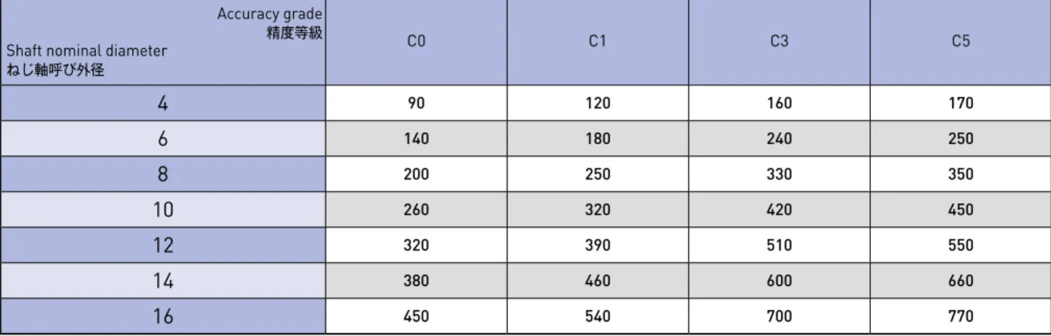
●転造ボールねじ(Ct7&Ct10)の製作限界長さ
Maximum limit of overall lengths for Rolled Ball Screws(Ct7 & Ct10)
Unit(単位):mm
Unit(単位):mm Accuracy grade
Shaft nominal diameter 精度等級 ねじ軸呼び外径
C0 C1 C3 C5
4 90 120 160 170
6 140 180 240 250
8 200 250 330 350
10 260 320 420 450
12 320 390 510 550
14 380 460 600 660
16 450 540 700 770
Shaft nominal diameter ねじ軸呼び外径
Maximum length 限界長さ
4 240
5 300
6 350
8 450
10 650
12 700
13 700
14 700
15 1000
注1)製作限界長さを超える場合はKSSへお問い合わせください。
注2)転造ボールねじの限界長さは、両端25mmずつの不完全ねじ部を含んだ値です。
Note 1)If required length exceeds the number in table above, please ask KSS representative.
Note 2)Maximum limit of overall length for Rolled Ball Screws includes 25mm of incomplete thread area at both end.
注1)製作限界長さを超える場合はKSSへお問い合わせください。
Note 1)If required length exceeds the number in table above, please ask KSS representative.
図 A-82 :移動量誤差線図
Fig. A-82 : Travel deviation diagram
Useful travel(lu)/ねじ部有効長さ(lu)
la
lm
V300
Vu ls
lo
Travel error 移動量誤差
V2π
+
T
ep
− 0
2π
300mm
Ball Screwボールねじ Technical descriptionボールねじ技術解説 Ball Screwボールねじ Technical descriptionボールねじ技術解説 表 A-83 :精密ボールねじ(位置決め用: C系列)の代表移動量誤差(±ep)と変動(Vu)の許容値
Table A-83 : Tolerance on actual mean travel deviation (±ep) and
permissible variation of precision Ball Screws (for positioning : C series)
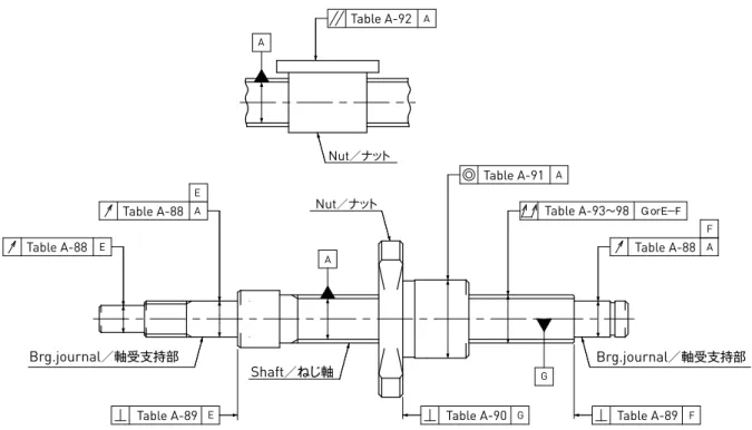
図 A-86 :取付け部精度記入例
Fig. A-86 : Description of Run-out and location tolerances for Ball Screws 表 A-84 :精密ボールねじ(位置決め用: C系列)における300mm及び1回転あたりの変動(V300)、(V2π)の許容値
Table A-84 : Permissible travel variation V300, V2π(for positioning : C series)
表 A-85 : Ct系列(7,10級)の300mmに対する変動(V300)
Table A-85 : Permissible travel variation V300 for Ct series(7,10 grade)
Unit(単位):μm
Unit(単位):μm
Unit(単位):μm
Accuracy Grade
精度等級 C0 C1 C3 C5
Effective screw length(mm) ねじ部有効長さ(mm)
を超えOver Up to
以下 ±ep Vu ±ep Vu ±ep Vu ±ep Vu
ー 100 3 3 3.5 5 8 8 18 18
100 200 3.5 3 4.5 5 10 8 20 18
200 315 4 3.5 6 5 12 8 23 18
315 400 5 3.5 7 5 13 10 25 20
400 500 6 4 8 5 15 10 27 20
500 630 6 4 9 6 16 12 30 23
630 800 7 5 10 7 18 13 35 25
800 1000 8 6 11 8 21 15 40 27
Accuracy grade
精度等級 C0 C1 C3 C5
Item
項目 V300 V2π V300 V2π V300 V2π V300 V2π Permissible value
許容値 3.5 3 5 4 8 6 18 8
Accuracy grade
精度等級 Ct7 Ct10
V300 52 210
Ct系列(7,10級)の代表移動量誤差は次式で計算します。
Tolerance on actual mean travel deviation(ep)is calculated as follows.
ep= ×V300 lu:ねじ部有効長さ
Effective Screw thread length 300
2×lu
1997年よりボールねじの日本工業規格(JIS B1191, 1192) がISOと の 整 合 性 を 図 る 目 的 で 改 訂 さ れ ま し た。(JIS B1192-1997に統一)
精度等級に関しては、C系列(従来のJIS規格 C0,1,3,5)とCp、 Ct系列(ISOとの整合性を図った規格)が制定されました。
KSSでは、JIS B 1192-1997に準拠し、0,1,3,5級に関しては、
C系列を、7,10級に関しては、Cp、Ct系列を採用しています。
In the purpose of correspondence to ISO, Japan Industrial Standard (JIS B1191, 1192)of Ball Screw was revised in 1997.(JIS B1192-1997 unified)
Regarding accuracy grade, C series(current JIS C0, 1, 3, 5) and Cp, Ct series (standard corresponding to ISO) was established. KSS conforms to JIS B1192- 1997 and adopts C series regarding 0,1,3,5 grade, Cp,
ボールねじの取付け部精度
Ball Screw Run-out and location tolerances
1997年よりボールねじの日本工業規格(JIS B1191, 1192) がISOとの整合性を図る目的で改訂されました(JIS B1192- 1997に統一)。
精度等級に関しては、C系列(従来のJIS規格 C0,1,3,5)とCp、 Ct系列(ISOとの整合性を図った規格)が制定され、取付け部 精度の表記法と規格が、C系列とCp,Ct系列で若干異なって いますが、KSSでは、下図(図 A-86)の表記と規格値(C系列)
で統一し、7級、10級に関しては、Cp,Ct系列の規格を参考に 運用しています。
In the purpose of correspondence to ISO, Japan Industrial Standard (JIS B1191, 1192)of Ball Screw was revised in 1997 (JIS B1192-1997 unified).
Regarding accuracy grade, C series(current JIS C0, 1, 3, 5) and Cp, Ct series (standard corresponding to ISO) was established. There are some differences between C series and Cp, Ct series in notation and tolerances for accuracy of Ball Screw mounting section, but KSS uses notation of Fig. A-86 below and standard tolerance value, which conforms to C series standard, and regarding 7 grade, 10 grade, KSS refers to Cp, Ct series standard.
E
GorE−F A
E
F G
A A
G
F A
Table A-88 E
Table A-89 Table A-88
Table A-92
A
A
Brg.journal/軸受支持部
Shaft/ねじ軸 Nut/ナット
Brg.journal/軸受支持部 Nut/ナット
Table A-91
Table A-88
Table A-89 Table A-90
Table A-93〜98
Ball Screwボールねじ Technical descriptionボールねじ技術解説 Ball Screwボールねじ Technical descriptionボールねじ技術解説
表 A-88 : ねじ軸のねじ溝面に対する支持部外径の半径方向円周振れ
及びねじ軸の支持部軸線に対する部品取付け部の半径方向円周振れ
Table A-88 : Radial Run-out of Bearing seat related to the centerline of screw groove and Radial Run-out of journal diameter related to the Bearing seat
表 A-89 :ねじ軸の支持部軸線に対する支持部端面の直角度
Table A-89 : Axial Run-out (Perpendicularity) of Shaft(Bearing) face related to the centerline of the Bearing seat
表 A-90 :ねじ軸の軸線に対するナット基準端面またはフランジ取付け面の直角度
Table A-90 : Axial Run-out (Perpendicularity) of Ball Nut location face related to the centerline of Screw Shaft
表 A-91 :ねじ軸の軸線に対するナット外周面(円筒形の場合)の半径方向円周振れ
Table A-91 : Radial Run-out of Ball Nut location diameter related to the centerline of Screw Shaft
表 A-92 :ねじ軸の軸線に対するナット外周面(平面形取付けの場合)の平行度
Table A-92 : Parallelism of rectangular Ball Nut related to the centerline of Screw Shaft
Unit(単位):μm
Unit(単位):μm
Unit(単位):μm
Unit(単位):μm
Unit(単位):μm
Shaft nominal diameter (mm)
ねじ軸呼び外径(mm) Permissible deviation of Radial Run-out 振れ公差(最大)
Over
を超え Up to
以下 C0 C1 C3 C5 C7 C10
ー 8 3 5 8 10 14 40
8 12 4 5 8 11 14 40
12 20 4 6 9 12 14 40
Shaft nominal diameter (mm)
ねじ軸呼び外径(mm) Permissible deviations of Axial Run-out(Perpendicularity) 直角度公差(最大)
Over
を超え Up to
以下 C0 C1 C3 C5 C7 C10
ー 8 2 3 4 5 7 10
8 12 2 3 4 5 7 10
12 20 2 3 4 5 7 10
Nut outside diameter (mm)
ナット外径 Permissible deviations of Axial Run-out(Perpendicularity) 直角度公差(最大)
Over
を超え Up to
以下 C0 C1 C3 C5 C7 C10
ー 20 5 6 8 10 14 20
20 32 5 6 8 10 14 20
32 50 6 7 8 11 18 30
Nut outside diameter (mm)
ナット外径 Permissible deviations of Radial Run-out 振れ公差(最大)
Over
を超え Up to
以下 C0 C1 C3 C5 C7 C10
ー 20 5 6 9 12 20 40
20 32 6 7 10 12 20 40
32 50 7 8 12 15 30 60
Mounting length (mm)
取付け基準長さ(mm) Permissible deviations of Parallelism 平行度公差(最大)
Over
を超え Up to
以下 C0 C1 C3 C5 C7 C10
ー 50 5 6 8 10 17 30
50 100 7 8 10 13 17 30
この項目の測定には、ねじ軸軸線の全振れの影響が含まれ るので、その補正が必要となります。その補正方法としては、
ねじ軸全長と、支点と測定点間の距離(L1,L2)との比によっ て(図 A-87参照)、p-A809〜A811ページの表 A-93〜98の ねじ軸軸線の全振れ公差から補正値(下式参照)を求め、表 A-88の公差に加えて適用します。
This measurement item is affected by Total Run-out of the Screw Shaft, and so it must be corrected as follows. Find the corrected value from the Total Run- out tolerances given in Tables A-93〜98 on p-A809〜 A811 using the ratio of the total Shaft length to the distance between the supporting point and the measuring point(L1,L2)(see Fig. A-87), and add the values obtained to the tolerance given in Table A-88.
L1 ,L2: 支点と測定間の距離(mm)
Distance btw supporting pt & measuring pt(mm) 円周振れ補正値= 全長 ×測定間距離(L1またはL2)
全振れ公差(表 A-93〜98)
Compensation Value of Run-out= Total shaft length ×(L1 or L2) Tolerance of total Run-out(Table A-93〜98)
L1 Balls/鋼球 L2
図 A-87 :円周振れの補正
Fig. A-87 : Compensation of Radial Run-out
Ball Screwボールねじ Technical descriptionボールねじ技術解説 Ball Screwボールねじ Technical descriptionボールねじ技術解説 表 A-93 :ねじ軸軸線の半径方向全振れ(C0)
Table A-93 : Total Run-out in radial direction of Screw Shaft related to the centerline of Screw Shaft(C0) 表 A-95 :ねじ軸軸線の半径方向全振れ(C3)
Table A-95 : Total Run-out in radial direction of Screw Shaft related to the centerline of Screw Shaft(C3)
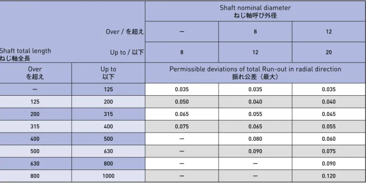
表 A-96 :ねじ軸軸線の半径方向全振れ(C5)
Table A-96 : Total Run-out in radial direction of Screw Shaft related to the centerline of Screw Shaft(C5) 表 A-94 :ねじ軸軸線の半径方向全振れ(C1)
Table A-94 : Total Run-out in radial direction of Screw Shaft related to the centerline of Screw Shaft(C1)
Unit(単位):mm Unit(単位):mm
Unit(単位):mm Unit(単位):mm
Shaft total length ねじ軸全長
Shaft nominal diameter ねじ軸呼び外径
Over / を超え ー 8 12
Up to / 以下 8 12 20
を超えOver Up to
以下 Permissible deviations of total Run-out in radial direction 振れ公差(最大)
ー 125 0.015 0.015 0.015
125 200 0.025 0.020 0.020
200 315 0.035 0.025 0.020
315 400 ー 0.035 0.025
400 500 ー 0.045 0.035
500 630 ー 0.050 0.040
630 800 ー ー 0.050
800 1000 ー ー 0.065
Shaft total length ねじ軸全長
Shaft nominal diameter ねじ軸呼び外径
Over / を超え ー 8 12
Up to / 以下 8 12 20
を超えOver Up to
以下 Permissible deviations of total Run-out in radial direction 振れ公差(最大)
ー 125 0.025 0.025 0.020
125 200 0.035 0.035 0.025
200 315 0.050 0.040 0.030
315 400 0.060 0.050 0.040
400 500 ー 0.065 0.050
500 630 ー 0.070 0.055
630 800 ー ー 0.070
800 1000 ー ー 0.095
Shaft total length ねじ軸全長
Shaft nominal diameter ねじ軸呼び外径
Over / を超え ー 8 12
Up to / 以下 8 12 20
を超えOver Up to
以下 Permissible deviations of total Run-out in radial direction 振れ公差(最大)
ー 125 0.035 0.035 0.035
125 200 0.050 0.040 0.040
200 315 0.065 0.055 0.045
315 400 0.075 0.065 0.055
400 500 ー 0.080 0.060
500 630 ー 0.090 0.075
630 800 ー ー 0.090
800 1000 ー ー 0.120
Shaft total length ねじ軸全長
Shaft nominal diameter ねじ軸呼び外径
Over / を超え ー 8 12
Up to / 以下 8 12 20
を超えOver Up to
以下 Permissible deviations of total Run-out in radial direction 振れ公差(最大)
ー 125 0.020 0.020 0.015
125 200 0.030 0.025 0.020
200 315 0.040 0.030 0.025
315 400 0.045 0.040 0.030
400 500 ー 0.050 0.040
500 630 ー 0.060 0.045
630 800 ー ー 0.060
800 1000 ー ー 0.075
Ball Screwボールねじ Technical descriptionボールねじ技術解説 Ball Screwボールねじ Technical descriptionボールねじ技術解説 表 A-97 :ねじ軸軸線の半径方向全振れ(C7)
Table A-97 : Total Run-out in radial direction of Screw Shaft related to the centerline of Screw Shaft(C7)
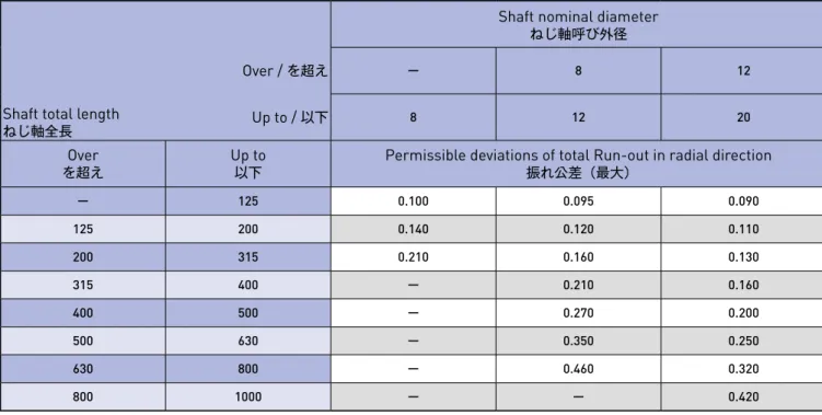
表 A-98 :ねじ軸軸線の半径方向全振れ(C10)
Table A-98 : Total Run-out in radial direction of Screw Shaft related to the centerline of Screw Shaft(C10)
Unit(単位):mm
Unit(単位):mm
Shaft total length ねじ軸全長
Shaft nominal diameter ねじ軸呼び外径
Over / を超え ー 8 12
Up to / 以下 8 12 20
を超えOver Up to
以下 Permissible deviations of total Run-out in radial direction 振れ公差(最大)
ー 125 0.060 0.055 0.055
125 200 0.075 0.065 0.060
200 315 0.100 0.080 0.070
315 400 ー 0.100 0.080
400 500 ー 0.120 0.095
500 630 ー 0.150 0.110
630 800 ー ー 0.140
800 1000 ー ー 0.170
Shaft total length ねじ軸全長
Shaft nominal diameter ねじ軸呼び外径
Over / を超え ー 8 12
Up to / 以下 8 12 20
を超えOver Up to
以下 Permissible deviations of total Run-out in radial direction 振れ公差(最大)
ー 125 0.100 0.095 0.090
125 200 0.140 0.120 0.110
200 315 0.210 0.160 0.130
315 400 ー 0.210 0.160
400 500 ー 0.270 0.200
500 630 ー 0.350 0.250
630 800 ー 0.460 0.320
800 1000 ー ー 0.420
ボールねじの取付け部精度測定方法
Measuring method of Ball Screw Run-out and location tolerances
●ねじ軸のねじ溝面に対する支持部外径の半径方向円周振れ
(表 A-88)
ねじ軸両端をVブロックで支持し、ねじ軸を回転させなが ら、ナット外周面に当てたダイヤルゲージの目盛を読みと ります。測定は支持部近傍の2か所で行います。
●ねじ軸の支持部軸線に対する部品取付け部の半径方向円 周振れ(表 A-88)
ねじ軸両端をVブロックで支持し、ねじ軸を回転させなが ら、部品取付け部に当てたダイヤルゲージの目盛を読みと ります。
●ねじ軸の支持部軸線に対する支持部端面の直角度
(表 A-89)
ねじ軸両端を両センタ穴で支持し、ねじ軸を回転させなが ら、支持部端面に当てたダイヤルゲージの目盛を読みとり ます。
** 図面表記は支持部外周面基準ですが、支持部外周面は、
センタ穴基準で加工しているため、支持部外周面にVブ ロックで支持したことと同等となります。
● Radial Run-out of Bearing seat related to the centerline of screw groove (Table A-88) Place the Ball Screw in identical V-blocks at both Bearing seat. Place the dial gauge perpendicular to the Nut cylindrical surface. Rotate Screw Shaft slowly and record the dial gauge readings.
Measurement should be done at near both ends of threaded part.
● Radial Run-out of journal diameter related to the Bearing seat(Table A-88)
Place the Ball Screw in identical V-blocks at both Bearing seats. Place the dial gauge perpendicular to the journal cylindrical surface. Rotate the Screw Shaft slowly and record the dial gauge readings.
● Axial Run-out (Perpendicularity) of shaft(Bearing) face related to the centerline of the Bearing seat
(Table A-89)
Support a Screw Shaft at both centers. Place the dial gauge perpendicular to the end face of the journal.
Rotate the Screw Shaft slowly and record the dial gauge readings.
** This method is equivalent to the one, which is supported at both Bearing seats, because Bearing seats are ground related to both centers.
Ball Screwボールねじ Technical descriptionボールねじ技術解説 Ball Screwボールねじ Technical descriptionボールねじ技術解説
●ねじ軸の軸線に対するナット基準端面 またはフランジ取付け面の直角度(表 A-90)
ねじ軸両端を両センタ穴で支持し、軸とナットを共に回転 させながら、ナットフランジ端面に当てたダイヤルゲージ の目盛を読みとります。
●ねじ軸の軸線に対するナット外周面の半径方向円周振れ
(表 A-91)
ねじ軸のナット近傍の外周面をVブロックで支持し、ナッ トを回転させながら、ナット外周面に当てたダイヤルゲー ジの目盛を読みとります。
●ねじ軸の軸線の半径方向全振れ(表 A-93〜98)
ねじ軸両端を両センタ穴またはVブロックで支持し、ねじ 軸を回転させながら、ねじ軸外周面またはナット外周面に 当てたダイヤルゲージの目盛を読みとります。測定は全域 にわたり、数か所行います。
● Axial Run-out (Perpendicularity) of Ball Nut location face related to the centerline of Screw Shaft (Table A-90)
Support the Ball Screw at both centers. Place the dial gauge perpendicular to the flange face. Rotate the Screw Shaft with Ball Nut slowly and record the dial gauge readings. Secure the Ball Nut against rotation on the Screw Shaft.
● Radial Run-out of Ball Nut location diameter related to the centerline of Screw Shaft
(Table A-91)
Place the Ball Screw on V-blocks at adjacent sides of the Ball Nut. Place the dial gauge perpendicular to the cylindrical surface of Ball Nut. Secure the Screw Shaft against rotation of Ball Nut. Rotate Ball Nut slowly and record the dial gauge readings.
● Total Run-out in radial direction of Screw Shaft related to the centerline of Screw Shaft
(Table A-93〜98)
Place the Ball Screw in identical V-blocks at both Bearing seats, or support the Ball Screw at both centers. Place the dial gauge with measuring shoe at the several points over the full thread length.
Rotate the Screw Shaft slowly and record the dial gauge readings. Maximum value of measurement should be the Total Run-out.
材質と熱処理、硬さ
Material and Heat treatment, Surface hardness
KSSボールねじの標準材質、熱処理と硬さは、表 A-99, 100 に示すとおりです。なお、シリーズや型式により多少異なる 場合がありますので、KSS提示の仕様図を参照ください。
Standard material of KSS Ball Screws, Heat treatment and Surface hardness are shown in table A-99, 100.
However, they vary depending on series or model number. Please refer to KSS drawings.
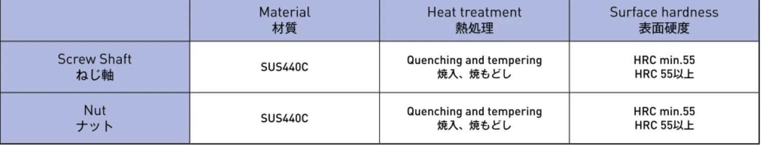
表 A-99 :通常品の材質と熱処理、硬さ
Table A-99 : Material, Heat treatment & Surface hardness for regular items
表 A-100 :ステンレス品の材質と熱処理、硬さ
Table A-100 : Material, Heat treatment & Surface hardness for stainless steel items Material
材質 Heat treatment
熱処理 Surface hardness
表面硬度 Screw Shaft
ねじ軸 SCM415 Carburizing and quenching
浸炭焼入 HRC 58-62
Nut
ナット SCM415 Carburizing and quenching
浸炭焼入 HRC 58-62
Material
材質 Heat treatment
熱処理 Surface hardness
表面硬度 Screw Shaft
ねじ軸 SUS440C Quenching and tempering
焼入、焼もどし HRC min.55 HRC 55以上
ナットNut SUS440C Quenching and tempering
焼入、焼もどし HRC min.55 HRC 55以上
注)表中に示す硬度は、ボールねじ部の表面硬度を表します。
Note)Hardness on table shows surface hardness of thread part.
注)表中に示す硬度は、ボールねじ部の表面硬度を表します。
Note)Hardness on table shows surface hardness of thread part.
Ball Screwボールねじ Technical descriptionボールねじ技術解説 Ball Screwボールねじ Technical descriptionボールねじ技術解説
許容アキシアル荷重
Permissible Axial load 許容回転数 Permissible speed
ねじ軸には、できる限り引張り荷重が作用するような使い 方をおすすめします。しかし使用条件によっては、圧縮荷重 が作用する場合があり、このときはねじ軸に座屈が生じな いよう検討する必要があります。
また、特に取付け間距離が接近している場合は、取付け方法 に関係なく許容引張、または圧縮荷重や基本静定格荷重Coa の制約を受けます。
座屈荷重、許容引張、許容圧縮荷重については、以下の計算 式で算出できます。
回転を伴うねじ軸は、取付方法によって一定の限界となる 回転数が決められており、この値に近くなると共振を起こ し、運転不能となることがあります。
またボールねじは、取付方法に関係なく、循環部の破損をま ねく限界回転数が存在します。
It is recommended that Ball Screw Shafts be used almost exclusively under tension load conditions.
However, in some applications, compression loads may exist, and under such conditions it must be determined that Shaft buckling will not occur.
Also, when the mounting span distance is short, there is a restriction on the permissible tension or compression load and the Basic Static Load Rating Coa unrelated to mounting.
Buckling load, permissible tension and permissible compression load can be calculated below.
For Screw Shaft rotation, the mounting method determines the established rotation limits. When this value is approached, resonance phenomenon can occur, and operation becomes impossible. There is also rotation limit which causes damages to
recirculating parts. This limit is unrelated to mounting methods.
●座屈に対する許容圧縮荷重の計算式
Permissible compression load calculation for buckling
●危険速度に対する許容回転数の計算式
Permissible speed calculation for critical speed
●ねじ軸の降伏応力に対する許容引張、圧縮荷重の計算式
Permissible tension, compression load calculation for Screw Shaft yield stress α:安全率(Safety Factor) 0.5
E :ヤング率(Youngʻs modulus) 2.08 ×10⁵ N/mm(2 MPa){21,200kgf/mm2} I :ねじ軸断面の最小2次モーメント(Screw Shaft minimum moment of inertia of area)
β:安全係数(Safety Factor) 0.8
E :ヤング率(Youngʻs modulus) 2.08 ×10⁵ N/mm2(MPa){21,200kgf/mm2} I :ねじ軸断面の最小2次モーメント(Screw Shaft minimum moment of inertia of area)
σ:許容応力(Permissible stress) 98N/mm2(MPa){10kgf/mm2} A :ねじ軸の最小断面積(Screw Shaft minimum section area)
d :ねじ軸谷径(Screw Shaft Root diameter) mm d :ねじ軸谷径(Screw Shaft Root diameter) mm L :取付け間距離(Mounting span distance) mm n :ボールねじの取付け方法によって定まる係数(Factor for Ball Screw mounting method)
支持−支持(Supported−Supported) n = 1 固定−支持(Fixed−Supported) n = 2 固定−固定(Fixed−Fixed) n = 4 固定−自由(Fixed−Free) n = 1/4
λ:ボールねじの取付け方法によって定まる係数(Factor for Ball Screw mounting method) 支持−支持(Supported−Supported)λ=π
固定−支持(Fixed−Supported) λ= 3.927 固定−固定(Fixed−Fixed) λ= 4.730 固定−自由(Fixed−Free) λ= 1.875
d :ねじ軸谷径(Screw Shaft Root diameter) mm g :重力加速度(Gravity acceleration) 9.8×103 mm/sec2 γ:材料の比重(Material specific gravity) 7.7×10ー5 N/mm3{7.85×10ー6kgf/mm3}
L :取付間距離(Mounting span distance) mm A :ねじ軸の最小断面積(Screw Shaft minimum section area)
P =α×
N =β× × minー1{rpm}
P =σ× A N{kgf} I =
I =
d4 mm4
d4 mm4 N{kgf} オイラーの式(Formula for Oiler)
L2 nπ2E・I
2π 60・λ2
γ・A ・L4 E ・I ・g
64 π
64 π
A = 4 d2 mm2 π
A = 4 d2 mm2 π
●循環部の破損に対する限界回転数
循環部の破損に対する限界回転数について、一般的には ボールねじのボール速度dn値(ねじ軸呼び外径×回転数)
によって上限を設ける場合がほとんどですが、KSSボール ねじのようなミニチュアボールねじには、dn値の概念が 当てはまりません。KSSボールねじの場合、循環部破損に よる限界回転数は、3,500〜4,000rpm程度と考えてくだ さい。この値は、使用条件や環境によっても異なりますの で、詳細はKSSまでお問い合わせください。
● Rotation limits for damage on recirculating parts Generally, regarding critical speed for damage on recirculating parts, limitation is established by dn value, which is multiplied Shaft nominal diameter of revolution, but dn value cannot be applied to Miniature Ball Screws. For KSS Ball Screws, please consider rotation limits by damage on recirculating parts as 3,500 to 4,000rpm. This value varies
depending on operating conditions and environment.
Please inquire KSS for details.
Ball Screwボールねじ Technical descriptionボールねじ技術解説 Ball Screwボールねじ Technical descriptionボールねじ技術解説
ボールねじの取付け方法
Ball Screw mounting methods 軸方向すきまと予圧 Axial play and Preload
ボールねじの代表的な取付け方法を図 A-101に示します。
取付け方法は、座屈に対する許容アキシアル荷重、および危 険速度に対する許容回転数に影響しますので、強度や回転 数の検討の際にご利用ください。
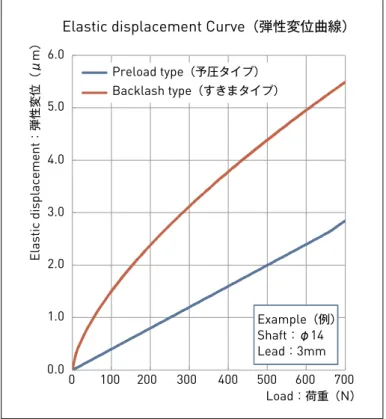
一般に通常のシングルナットのボールねじでは、ねじ軸と ナットの間にわずかな軸方向すきまが存在します。した がって、シングルナットボールねじに軸方向荷重が作用す ると、上述の軸方向すきまと軸方向荷重による弾性変位量 の和が、バックラッシュとして発生します。このバックラッ シュを無くすために、ボールねじでは、軸方向すきまを負の 状態にする、すなわち、あらかじめねじ軸とナットの間の ボールに弾性変形を与えておく「予圧」という方法が採られ ます。
Typical Ball Screw's mounting methods are shown in Fig. A-101. Mounting configuration affects permissible Axial load in relation to buckling, as well as
permissible speed in relation to critical speed. Please refer to below when studying strength and speed.
For standard Single Nut Ball Screws under normal conditions, a slight Axial play exists between the Screw Shaft and Nut. Consequently, when Axial loads act on Single Nut Ball Screws, total amount of Axial play and Elastic displacement due to Axial load becomes backlash. In order to prevent this backlash in Ball Screws, the Axial play can be reduced to a negative value. That is what we call “Preload", which is the method of causing Elastic deformation to the Balls between the Screw Shaft and Nut in advance.
●軸方向すきま
KSSボールねじのすきま記号と軸方向すきまの許容値を 表 A-102に示します。
また、ボールねじの精度等級とすきま記号の組み合わせは、
表 A-103に示すとおりです。
●Axial play
Symbol and permissible value for Axial play are shown in Table A-102.
Combination of accuracy grade and symbol are shown in Table A-103.
表 A-102 :すきま記号と軸方向すきまの許容値
Table A-102 : Symbol and permissible value for Axial play
表 A-103 :精度等級とすきま記号の組み合わせ
Table A-103 : Combination of accuracy grade and Axial play Symbol
すきま記号 0 02 05 20 50
Axial play
軸方向すきま 0 (0Preloading (予圧) ) 0.002 max.0.002以下 0.005 max.0.005以下 0.02 max.0.02以下 0.05 max.0.05以下
Symbol すきま記号 Accuracy grade 精度等級
0 02 05 20 50
C0 C0-0 ー ー ー ー
C1 C1-0 C1-02 ー ー ー
C3 C3-0 C3-02 C3-05 C3-20 C3-50
C5 ー ー C5-05 C5-20 C5-50
Unit(単位):mm
図 A-101 :ボールねじの取付け方法
Fig. A-101 : Ball Screw mounting methods
L : Buckling load(Fixed−Supported)
L : Critical speed(Fixed−Supported) Slide/移動
座屈荷重(固定−支持)
危険速度(固定−支持)
Motor/モータ
L : Critical speed(Fixed−Supported) L : Buckling load(Fixed−Fixed)
Slide/移動 座屈荷重(固定−固定)
危険速度(固定−支持)
Motor/モータ
L : Buckling load(Fixed−Fixed)
L : Critical speed(Fixed−Fixed) Slide/移動
座屈荷重(固定−固定)
危険速度(固定−固定)
Motor/モータ
L : Buckling load(Fixed−Fixed)
L : Critical speed(Fixed−Free) Slide/移動
座屈荷重(固定−固定)
危険速度(固定−自由)
Motor/モータ
Slide/移動
L L :: Critical speed Buckling load((FixedFixed−−FixedFixed)/危険速度(固定−固定))/座屈荷重(固定−固定)
Slide/移動
L : Critical speed(Fixed−Free)/危険速度(固定−自由)
L : Buckling load(Fixed−Free)/座屈荷重(固定−自由)
L : Buckling load(Fixed−Fixed)
Slide/移動 座屈荷重(固定−固定)
Motor/モータ