1/23
EC Kit P/N: CA04136-K027-ECS P3FY-1390-01
GP5-141∼146 ファームウェア改版手順書
Firmware Update Procedure for GP5-141∼146
GP5-141/142/143 Firmware Version 4.08-0-12
GP5-144/145/146 Firmware Version 5.08-0-12
2001 年 3 月 富士通株式会社
March, 2001 Fujitsu Limited
2/23
目次
Contents
日本文は「9. 付録(メッセージリスト)」までです。 English writings are from ’10. Summary of This Document’.
1 . 本 書 の 概 要 _ _ _ _ _ _ _ _ _ _ _ _ _ _ _ _ _ _ _ _ _ _ _ _ _ _ _ _ _ _ _ _ _ _ _ _ _ _ _ _ _ _ _ _ _ _ _ _ _ 4 2 . 作 業 対 象 カ ー ド と フ ァ ー ム ウ ェ ア 詳 細 _ _ _ _ _ _ _ _ _ _ _ _ _ _ _ _ _ _ _ _ _ _ _ _ _ _ _ _ _ _ 4 2.1 作業対象カード _ _ _ _ _ _ _ _ _ _ _ _ _ _ _ _ _ _ _ _ _ _ _ _ _ _ _ _ _ _ _ _ _ _ _ _ _ _ _ _ _ _ _ _ _ 4 2.2 改 版 対 象 、 適 用 フ ァ ー ム ウ ェ ア 版 数 _ _ _ _ _ _ _ _ _ _ _ _ _ _ _ _ _ _ _ _ _ _ _ _ _ _ _ _ _ _ _ 5 2.3 フ ァ ー ム ウ ェ ア 変 更 内 容 _ _ _ _ _ _ _ _ _ _ _ _ _ _ _ _ _ _ _ _ _ _ _ _ _ _ _ _ _ _ _ _ _ _ _ _ _ _ _ 6 3 . 部 材 確 認 _ _ _ _ _ _ _ _ _ _ _ _ _ _ _ _ _ _ _ _ _ _ _ _ _ _ _ _ _ _ _ _ _ _ _ _ _ _ _ _ _ _ _ _ _ _ _ _ _ _ 8 3.1 EC 部材 _ _ _ _ _ _ _ _ _ _ _ _ _ _ _ _ _ _ _ _ _ _ _ _ _ _ _ _ _ _ _ _ _ _ _ _ _ _ _ _ _ _ _ _ _ _ _ _ _ _ _ 8 3.2 そ の 他 の 必 要 部 材 _ _ _ _ _ _ _ _ _ _ _ _ _ _ _ _ _ _ _ _ _ _ _ _ _ _ _ _ _ _ _ _ _ _ _ _ _ _ _ _ _ _ _ _ 8 4 . 作 業 対 象 カ ー ド の 確 認 _ _ _ _ _ _ _ _ _ _ _ _ _ _ _ _ _ _ _ _ _ _ _ _ _ _ _ _ _ _ _ _ _ _ _ _ _ _ _ _ _ 9 5 . 作 業 を 行 う 前 に _ _ _ _ _ _ _ _ _ _ _ _ _ _ _ _ _ _ _ _ _ _ _ _ _ _ _ _ _ _ _ _ _ _ _ _ _ _ _ _ _ _ _ _ _ _ 9 5.1 RAS 支 援 サ ー ビ ス の 起 動 監 視 機 能 設 定 に つ い て _ _ _ _ _ _ _ _ _ _ _ _ _ _ _ _ _ _ _ _ _ _ _ 9 5.2 フ ァ ー ム ウ ェ ア 書 換 中 の リ セ ッ ト / 電 源 オ フ 禁 止 _ _ _ _ _ _ _ _ _ _ _ _ _ _ _ _ _ _ _ _ _ _ 9 5.3 ハ ー ド デ ィ ス ク の 状 態 確 認 _ _ _ _ _ _ _ _ _ _ _ _ _ _ _ _ _ _ _ _ _ _ _ _ _ _ _ _ _ _ _ _ _ _ _ _ _ _ 9 5.4 サ ー バ 本 体 の 電 源 オ フ お よ び 再 起 動 確 認 _ _ _ _ _ _ _ _ _ _ _ _ _ _ _ _ _ _ _ _ _ _ _ _ _ _ _ 1 0 5.5 アレイ 構 成 情 報 の バ ッ ク ア ッ プ に つ い て _ _ _ _ _ _ _ _ _ _ _ _ _ _ _ _ _ _ _ _ _ _ _ _ _ _ _ 1 0 5.6 MS-DOS 環 境 に つ い て _ _ _ _ _ _ _ _ _ _ _ _ _ _ _ _ _ _ _ _ _ _ _ _ _ _ _ _ _ _ _ _ _ _ _ _ _ _ _ _ 1 0 6 . 作 業 手 順 _ _ _ _ _ _ _ _ _ _ _ _ _ _ _ _ _ _ _ _ _ _ _ _ _ _ _ _ _ _ _ _ _ _ _ _ _ _ _ _ _ _ _ _ _ _ _ _ _ 1 1 6.1 MS-DOS 起動手順 _ _ _ _ _ _ _ _ _ _ _ _ _ _ _ _ _ _ _ _ _ _ _ _ _ _ _ _ _ _ _ _ _ _ _ _ _ _ _ _ _ _ _ 1 1 6.1.a Server Wizard CD-ROM で MS-DOS を起動する場合 ______________________ 11 6.1.b FD で MS-DOS を起動する場合_________________________________________ 11 6.2 フ ァ ー ム ウ ェ ア 改 版 手 順 _ _ _ _ _ _ _ _ _ _ _ _ _ _ _ _ _ _ _ _ _ _ _ _ _ _ _ _ _ _ _ _ _ _ _ _ _ _ 1 1 7 . 作 業 後 の 確 認 項 目 _ _ _ _ _ _ _ _ _ _ _ _ _ _ _ _ _ _ _ _ _ _ _ _ _ _ _ _ _ _ _ _ _ _ _ _ _ _ _ _ _ _ _ 1 3 7.1 フ ァ ー ム ウ ェ ア 版 数 確 認 _ _ _ _ _ _ _ _ _ _ _ _ _ _ _ _ _ _ _ _ _ _ _ _ _ _ _ _ _ _ _ _ _ _ _ _ _ _ 1 3 7.2 OS の起動確認 _ _ _ _ _ _ _ _ _ _ _ _ _ _ _ _ _ _ _ _ _ _ _ _ _ _ _ _ _ _ _ _ _ _ _ _ _ _ _ _ _ _ _ _ _ 1 3 8 . そ の 他 _ _ _ _ _ _ _ _ _ _ _ _ _ _ _ _ _ _ _ _ _ _ _ _ _ _ _ _ _ _ _ _ _ _ _ _ _ _ _ _ _ _ _ _ _ _ _ _ _ _ _ 1 3 9 . 付 録 ( メ ッ セ ー ジ リ ス ト ) _ _ _ _ _ _ _ _ _ _ _ _ _ _ _ _ _ _ _ _ _ _ _ _ _ _ _ _ _ _ _ _ _ _ _ _ _ 1 4 1 0 . Summary of This Document _ _ _ _ _ _ _ _ _ _ _ _ _ _ _ _ _ _ _ _ _ _ _ _ _ _ _ _ _ _ _ _ _ _ _ 1 5 1 1 . Target Products and Firmware Detail _ _ _ _ _ _ _ _ _ _ _ _ _ _ _ _ _ _ _ _ _ _ _ _ _ _ _ _ 1 5
3/23
11.2 Target/New Firmware Version _ _ _ _ _ _ _ _ _ _ _ _ _ _ _ _ _ _ _ _ _ _ _ _ _ _ _ _ _ _ _ _ _ 1 6 11.3 Firmware Change History _ _ _ _ _ _ _ _ _ _ _ _ _ _ _ _ _ _ _ _ _ _ _ _ _ _ _ _ _ _ _ _ _ _ _ _ 1 7
1 2 . Accessories _ _ _ _ _ _ _ _ _ _ _ _ _ _ _ _ _ _ _ _ _ _ _ _ _ _ _ _ _ _ _ _ _ _ _ _ _ _ _ _ _ _ _ _ _ _ _ 1 9
12.1 EC Parts _ _ _ _ _ _ _ _ _ _ _ _ _ _ _ _ _ _ _ _ _ _ _ _ _ _ _ _ _ _ _ _ _ _ _ _ _ _ _ _ _ _ _ _ _ _ _ _ 1 9 12.2 Other Parts _ _ _ _ _ _ _ _ _ _ _ _ _ _ _ _ _ _ _ _ _ _ _ _ _ _ _ _ _ _ _ _ _ _ _ _ _ _ _ _ _ _ _ _ _ _ 1 9
1 3 . Identification of Target RAID Card _ _ _ _ _ _ _ _ _ _ _ _ _ _ _ _ _ _ _ _ _ _ _ _ _ _ _ _ _ _ 2 0 1 4 . Before the Firmware Update _ _ _ _ _ _ _ _ _ _ _ _ _ _ _ _ _ _ _ _ _ _ _ _ _ _ _ _ _ _ _ _ _ _ _ 2 0
14.1 Start Monitoring Function Setting of RAS Assist Service _ _ _ _ _ _ _ _ _ _ _ _ _ _ 2 0 14.2 Ban on System Reset and Power Supply Cut _ _ _ _ _ _ _ _ _ _ _ _ _ _ _ _ _ _ _ _ _ _ _ 2 0 14.3 Drive Status_ _ _ _ _ _ _ _ _ _ _ _ _ _ _ _ _ _ _ _ _ _ _ _ _ _ _ _ _ _ _ _ _ _ _ _ _ _ _ _ _ _ _ _ _ _ 2 0 14.4 System Seizing-acknowledgment _ _ _ _ _ _ _ _ _ _ _ _ _ _ _ _ _ _ _ _ _ _ _ _ _ _ _ _ _ _ _ 2 0 14.5 Backup of RAID Configuration _ _ _ _ _ _ _ _ _ _ _ _ _ _ _ _ _ _ _ _ _ _ _ _ _ _ _ _ _ _ _ _ _ 2 0 14.6 MS-DOS Environment _ _ _ _ _ _ _ _ _ _ _ _ _ _ _ _ _ _ _ _ _ _ _ _ _ _ _ _ _ _ _ _ _ _ _ _ _ _ 2 1
1 5 . Firmware Update Procedure _ _ _ _ _ _ _ _ _ _ _ _ _ _ _ _ _ _ _ _ _ _ _ _ _ _ _ _ _ _ _ _ _ _ _ 2 1
15.1 MS-DOS Start Procedure_ _ _ _ _ _ _ _ _ _ _ _ _ _ _ _ _ _ _ _ _ _ _ _ _ _ _ _ _ _ _ _ _ _ _ _ _ 2 1 15.1.a Start MS-DOS with the Server Wizard CD-ROM__________________________ 21 15.1.b Start MS-DOS with a FD_______________________________________________ 21 15.2 Firmware Update Procedure _ _ _ _ _ _ _ _ _ _ _ _ _ _ _ _ _ _ _ _ _ _ _ _ _ _ _ _ _ _ _ _ _ _ 2 2
1 6 . Confirmations after the Update _ _ _ _ _ _ _ _ _ _ _ _ _ _ _ _ _ _ _ _ _ _ _ _ _ _ _ _ _ _ _ _ _ 2 3
16.1 Confirmation of Firmware Version _ _ _ _ _ _ _ _ _ _ _ _ _ _ _ _ _ _ _ _ _ _ _ _ _ _ _ _ _ _ 2 3 16.2 Confirmation of OS Start _ _ _ _ _ _ _ _ _ _ _ _ _ _ _ _ _ _ _ _ _ _ _ _ _ _ _ _ _ _ _ _ _ _ _ _ _ 2 3
1 7 . Others_ _ _ _ _ _ _ _ _ _ _ _ _ _ _ _ _ _ _ _ _ _ _ _ _ _ _ _ _ _ _ _ _ _ _ _ _ _ _ _ _ _ _ _ _ _ _ _ _ _ _ 2 3 1 8 . Appendix (Message List) _ _ _ _ _ _ _ _ _ _ _ _ _ _ _ _ _ _ _ _ _ _ _ _ _ _ _ _ _ _ _ _ _ _ _ _ _ _ 2 3
4/23
1. 本書の概要
本書は、SCSI アレイコントローラカード(以降、アレイカード)の BIOS/ファームウ ェアのアップグレード作業について記載しています。2. 作業対象カードとファームウェア詳細
2.1 作業対象カード
表 2-1 に本作業の対象アレイカードを示します。 表 2-1 作業対象アレイカード 代表型名 代表型名のカードと同一カードの他型名GP5-141 GP5-141A, GP5B141, GP5B141A, GP5U141, GP5BU141 GP5-142 GP5B142, GP5U142
GP5-143 GP5B143
GP5-144 GP5B144, GP5BU144, GP5B1U442, GP5B1U443, GP5B1U444, GP5B1U445, GP5B1U446
GP5-1441 GP5B1441, GP5B1U447, GP5B1U44B, GP5B1U44C, GP5B1U44D
GP5-145 GP5B145, GP5B1U451, GP5B1U452, GP5B1U453, GP5B1U454, GP5B1U455, GP5B1U457
GP5-146 GP5B146, GP5B1U461, GP5B1U462, GP5B1U463, GP5B1U464, GP5B1U466
5/23
2.2 改版対象、適用ファームウェア版数
改版対象 BIOS/ファームウェア(F/W)版数と、本作業実施後の BIOS/ファームウェ ア(F/W)版数を表 2-2 に示します。 表 2-2 改版対象 BIOS/F/W 版数と作業後の BIOS/F/W 版数 代表型名 (ベンダ型名) 改版対象版数 作業後版数 GP5-141 (DAC960PG) BIOS V4.10-21, F/W V4.04-0-03 BIOS V4.10-27, F/W V4.04-0-52 BIOS V4.10-41, F/W V4.04-0-52 BIOS V4.10-41, F/W V4.04-F-56 BIOS V4.10-50, F/W V4.08-0-12 GP5-142 (DAC960PGL) BIOS V4.10-21, F/W V4.04-0-03 BIOS V4.10-27, F/W V4.04-0-52 BIOS V4.10-41, F/W V4.04-0-52 BIOS V4.10-41, F/W V4.04-F-56 BIOS V4.10-50, F/W V4.08-0-12 GP5-143 (DAC960PTL1) BIOS V4.10-34, F/W V4.06-0-64 BIOS V4.10-41, F/W V4.07-0-12 BIOS V4.10-50, F/W V4.08-0-12 GP5-144 (DAC1164P) BIOS V4.10-34, F/W V5.06-0-64 BIOS V4.10-38, F/W V5.06-0-70 BIOS V4.10-41, F/W V5.07-0-12 BIOS V4.10-50, F/W V5.08-0-12 GP5-1441(DAC1164P) BIOS V4.10-41, F/W V5.07-0-12 BIOS V4.10-50, F/W V5.08-0-12
GP5-145 (DAC1164P)
BIOS V4.10-41, F/W V5.07-0-11
BIOS V4.10-41, F/W V5.07-0-12 BIOS V4.10-50, F/W V5.08-0-12
GP5-146
6/23
2.3 ファームウェア変更内容
ファームウェア変更履歴を表 2-3 に示します。 表 2-3 ファームウェア変更履歴 代表型名 版数 変更内容 F/W V4.03-0-03 ・ 初版 F/W V4.04-0-52 ・ データコンペアエラー障害修正 (EC № 基資料-10-09011) F/W V4.04-F-56 ・ HDD キャビネット(GP5S621/GP5-R1DC1) 連結接続制限解除 ・ Add Capacity 機能使用制限解除 (障害あり。TR 発行№ TA05028 参照) ・ GRANPOWER5000 モデル 570/670 リブート 時の起動ストップ問題の修正 ・ RAID6 使用制限解除 ・ HDD 交換後、HDD エラーカウントがクリア されない問題の修正 ・ リビルド実施不可障害修正 (TR 発行№ T994031) ・ HDD 複数 DED 障害修正 (TR 発行№ T997025) GP5-141/142 F/W V4.08-0-12 ・ Windows2000 環境でのメモリダンプ取得不 可障害の修正(TR 発行№ TA12015) ・ Add Capacity 後の構成異常障害の修正 (TR 発行№ TA05028) ・ SCSI エラーリカバリ処理改善 F/W V4.06-0-64 ・ 初版 F/W V4.07-0-12 ・ バックグラウンド初期化(BGI)サポート (TR 発行№ T997019) ・ リビルド実施不可障害修正 (TR 発行№ T994031) GP5-143 F/W V4.08-0-12 ・ 36GB HDD が、アレイカード交換後に DED と誤認識される問題の修正 (TR 発行№ TA06020) ・ SCSI エラーリカバリ処理改善 (次頁へ続く)7/23 (前頁から続き) 代表型名 版数 変更内容 F/W V5.06-0-64 ・ 初版 F/W V5.06-0-70 ・ ライトバックキャッシュ使用制限解除 ・ サーバ本体のオフ・オン間隔が1秒以下の場 合にアレイカード動作不能となる障害修正 (TR 発行№ T991002) F/W V5.07-0-11 ・ バックグラウンド初期化(BGI)サポート (TR 発行№ T997019) ・ リビルド実施不可障害修正 (TR 発行№ T994031) F/W V5.07-0-12
・ DACDIAG SCSI Cable Test で Fail を誤報告 する問題を修正 (TR 発行№ T997018) GP5-144 GP5-1441 GP5-145 GP5-146 F/W V5.08-0-12 ・ 36GB HDD が、アレイカード交換後に DED と誤認識される問題の修正 (TR 発行№ TA06020) ・ HDD 21 台以上接続状態でサーバ本体電源 オンするとアレイカード BIOS がタイムアウ トを誤検出する問題の修正 (TR 発行№ TA06012) ・ SCSI エラーリカバリ処理改善
8/23
3. 部材確認
本作業には、以下の部材が必要です。3.1 EC 部材
下記 3 つの EC 部材が揃っているか、あらかじめ確認してください。 フロッピーディスクは、複数のシステムで繰り返し使用することができます。版数シー ルが 100 個添付されていますので、作業対象カード 100 枚分の部材となります。 □ 手順書 「GP5-141∼146 ファームウェア改版手順書」(本書)×1 □ フロッピーディスク 「GP5-141/142/143 Firmware V4.08-0-12 GP5-144/145/146 Firmware V5.08-0-12」×1 □ 版数シール 「06」と記載されたシール ×1003.2 その他の必要部材
その他下記 2 つの部材が必要です。ユーザ品を使用する場合は、事前にユーザに確認し てください。 □ MS-DOS 起動媒体 作業対象サーバ本体に合わせ、サーバ本体添付の以下のいずれかの媒体を用意して ください。 ・CD-ROM「Server Wizard」 ・FD「セットアップディスク #2」 ・FD「システムコンフィグレーションディスク #2」 □ DACCF 媒体 作業対象カードに合わせ、以下のいずれかの媒体を用意してください。 ・FD「GP5-143/144/145/146 DACCF Utilities」 ・FD「GP5-141/142 DACCF ユーティリティ」 参考 本 EC 作業では、サーバ本体の電源オフ・オンを実施する必要がありますが、 サーバ本体に搭載されている HDD の版数が旧版の場合、電源オン時に既知 の障害が発生する可能性があります。 下記のテクニカルレポートを参照し、対象サーバ本体が該当する場合、本 EC と合わせて、事前に同 HDD の EC 部材も入手しておいてください。 TR 発行№ TA05035 「GP5000/580,680 他 電源投入時の HDD Not Ready 対策開始について」9/23
4. 作業対象カードの確認
サーバ本体起動時( OS 起動前の POST 時)に出力される下記表示の下線部にファームウ ェアバージョンが表示されますので、表 2-2 の作業対象ファームウェア版数と一致するフ ァームウェアのアレイカードが存在するかどうか確認してください。 複数のアレイカードが搭載されていた場合、搭載枚数分表示されますので、すべてのア レイカードのファームウェア版数を確認してください。DACxxxxx Firmware Version x.xx-x-xx
複数のアレイカードが搭載されていた場合、一枚でも作業対象カードが存在した場合は 本作業を適用する必要があります。また、サーバ本体にすでに適用済みのカードが混在搭 載されていても、作業の際にその適用済みカードをサーバ本体から取り出しておく必要は ありません。
5. 作業を行う前に
EC 作業を行う前に、以下の項目を必ず確認/実施してください。5.1 RAS 支援サービスの起動監視機能設定について
RAS 支援サービスがインストールされている場合、かつ、起動監視を行っている場合、 MS-DOS 起動中(ファームウェア改版中も含む)に意図しない電源切断や再起動が実行さ れる場合があります。本作業を行う前に、RAS 支援サービスの起動監視機能設定をすべて 「監視しない」に設定し、本作業が完了してから元の設定に戻してください。 RAS 支援サービス、および、起動監視機能設定についての詳細はサーバ本体添付の取扱 説明書を参照してください。5.2 ファームウェア書換中のリセット/電源オフ禁止
ファームウェアアップグレード中に予期せぬ電源切断やリセット等を行うと、搭載され ているアレイカードが動作しなくなることがあります。ファームウェアアップグレード中 に電源の切断およびシステムリセット等の操作が絶対に行われないようにしてください。 特に「5.1 RAS 支援サービスの起動監視機能設定について」で説明している設定にご注意 ください。5.3 ハードディスクの状態確認
DACADM(Drive Information )、または、DACCF(View/Update Configuration Define Pack)により、アレイカード配下のハードディスクの状態が全て「ONL」または「SBY」 であることを確認してください。万一、その他の状態のハードディスクが存在した場合に は、ハードディスク交換/リビルド等の保守作業を実施した後で本作業を実施してくださ い。
10/23
5.4 サーバ本体の電源オフおよび再起動確認
本作業を実施する前に、サーバ本体のシャットダウン、電源オフ、再起動を実施し、本 作業実施前のサーバ本体が正常に起動することを確認してください。24 時間稼動のサーバ や、長時間未使用のサーバに対して本作業を実施する場合に特に必要です。これは、OS 起 動ファイル等の通常アクセスされない領域が正常であることを確認しておき、EC 完了後の システムの起動で万一問題が発生した場合の原因切り分けを明確にする目的で行います。 この状態でシステムが起動出来ない場合、EC 作業を実施せず、通常保守手順に従った対処 を行う必要があります。 また、起動時に旧版ファームウェアによる障害が発生する可能性がありますので、あら かじめ下記のテクニカルレポートを参照しておいてください。 TR 発行№ T994031 「GP5-141/142/143/144 システムパック内の HDD の Rebuild 実施不可障害について」 万一、対処不可能な状態になった場合、一旦作業を中断し、サポート部門へインシデン トを採取し確認してください。 なお、サーバ本体の電源オフおよび再起動は、ユーザ立ち会いで実施してください。5.5 アレイ構成情報のバックアップについて
今回の作業を行う前に、最悪の場合に備えてディスクアレイの構成情報をフロッピー等 に保存しておく必要があります。現在のシステムのアレイ構成情報を保存していない場合、 本作業を行う前に DACCF のメインメニューから、「07. Tools」を選択し、「Backup Configuration」オプションにより、作業対象カードのアレイ構成情報をフロッピーに保存し ておいてください。5.6 MS-DOS 環境について
ファームウェア改版ユーティリティは、HIMEM.SYS や EMM386.EXE が組み込まれた MS-DOS 環境では正常に動作しないことがあります。必ず作業手順に記載されている手順 を守り、適切な環境で MS-DOS が起動されるようにしてください。11/23
6. 作業手順
作業手順は以下の通りです。作業を始めるにあたり「5. 作業を行う前に」の各項目につ いて確認が完了している必要がありますので、念のため再確認してください。6.1 MS-DOS 起動手順
必ず、下記の手順のいずれかで MS-DOS を起動してください。 6.1.a Server Wizard CD-ROM で MS-DOS を起動する場合(1) サーバ本体添付の Server Wizard CD-ROM を、CD-ROM ドライブにセットし、サー バ本体の電源を落としてください。(電源を落とす前に正しいシャットダウン処理 を行ってください。)
(2) サーバ本体の電源を投入してください。
(3) 「MS-DOS Startup Menu」から、「Basic(BIOS Environment Support Tools)」を選 択してください。 (4) MS-DOS プロンプトが表示されたら、「6.2 ファームウェア改版手順」へ進んでく ださい。 6.1.b FD で MS-DOS を起動する場合 (1) サーバ本体の電源を落としてください。(電源を落とす前に正しいシャットダウン 処理を行ってください。) (2) サーバ本体添付の FD「セットアップディスク #2」または「システムコンフィグレ ーションディスク #2」をフロッピーディスクドライブにセットしてください。 (3) サーバ本体の電源を投入してください。
(4) 「Starting MS-DOS …」と表示されたら(あるいは表示される前から)、[Shift] キ ーを押し続けて下さい。 (5) MS-DOS プロンプトが表示されたら、[Shift] キーを押すのを止め、「6.2 ファーム ウェア改版手順」へ進んでください。
6.2 ファームウェア改版手順
(1) MS-DOS の プ ロ ン プ ト 画 面 が 表 示 さ れ て い る 状 態 で 、 EC 部 材 の FD 「GP5-141/142/143 Firmware V4.08-0-12 GP5-144/145/146 Firmware V5.08-0-12」 をフロッピーディスクドライブにセットしてください(FD から MS-DOS を起動し た場合は FD を入れ換えてください)。(2) Server Wizard で MS-DOS を起動した場合、カレントディレクトリを FD ドライブ のルートディレクトリ (B:¥) にします。下記のように入力し、[Enter]キーを押して ください。FD から MS-DOS を起動した場合はこれを行う必要ありません。 B: ([Enter]キー入力)
参考
[Shift]キーを押した状態で MS-DOS を起動すると、AUTOEXEC.BAT 、 CONFIG.SYS がバイパスされ、HIMEM.SYS 等のドライバが組み込まれな い状態で MS-DOS を起動することができます。[Shift]キーが正しく認識され ると、セットアップメニューは表示されず、起動後すぐに MS-DOS プロン プトが表示されます。
12/23 (3) 下記のように入力し、[Enter]キーを押してください。データのアップグレードが開 始されます。ファームウェア改版ユーティリティが自動的に作業対象カードを識別 し、適当なデータをアレイカードに書き込みます。 UPDATE ([Enter]キー入力) (4) ファームウェアの改版が正常に完了すると、以下のように表示されますので、確認 してください。 Complete. (5) 表示を確認したら、 サーバ本体の電源を落とし、フロッピーディスクドライブ、 CD-ROM ドライブから媒体を取り出してください。 (6) 本 EC が適用済みであることを示すため、対象カード前面版の以下の位置に、EC 部 材の「06」と記載されたシールを貼り付けてください。すでに旧版のシールが貼ら れていた場合、旧シールの上から重ねて貼り付けてください。(図は GP5-144) 図 6-1 版数ラベル貼付位置 (7) 以上でファームウェア改版は終了です。 警告! ファームウェアアップグレード中に予期せぬ電源切断やリセット等を行う と、搭載されているカードが動作しなくなることがあります。ファームウェ アアップグレード中に電源の切断およびシステムリセット等の操作を絶対 に行わないでください。
13/23
7. 作業後の確認項目
ファームウェア改版後の確認項目は、以下の通りです。7.1 ファームウェア版数確認
サーバ本体起動時( OS 起動前の POST 時)に出力される下記表示の下線部を参照し、表 2-2 の 作 業 対 象 ア レ イ カ ー ド が 作 業 後 の フ ァ ー ム ウ ェ ア 版 数 ( V4.08-0-12 ま た は V5.08-0-12)になっていることを確認してください。 複数のアレイカードが搭載されていた場合、搭載枚数分表示されますので、すべてのア レイカードのファームウェア版数を確認してください。DACxxxxx Firmware Version x.xx-x-xx
7.2 OS の起動確認
ネットワーク OS(Windows 2000、Windows NT 、NetWare 等)が正常に起動すること を確認してください。
8. その他
EC 部材は、複数のシステムで繰り返し使用できます。 参考 Windows 2000 では、本 EC 適用後、最初の OS 起動時に下記のメッセージ が表示されることがあります。この場合、メッセージに従い、サーバ本体を 再起動してください。 「新しいデバイスのインストールが完了しました。新しい設定を有効にする にはコンピュータを再起動する必要があります。今すぐ再起動しますか?」14/23
9. 付録(メッセージリスト)
ファームウェア改版ユーティリティが出力するメッセージは以下の通りです。 □ Complete.
ファームウェア改版が正常終了したことを示します。 □ Firmware version is equal to index data.
すでに最新のファームウェアが適用されていることを示します。 □ Abnormal Ended.
ファームウェア改版が異常終了したことを示します。このメッセージの前に出力さ れているメッセージを参照し、適切な対処を行ってください。
□ Channel = xx, Target = yy, Dead Drive detected.
チャネル xx、ターゲット ID yy で、DED 状態の HDD が検出されたことを示します。 この場合、HDD 交換、リビルド等の保守作業終了後にファームウェア改版作業を 実施してください。
□ Standby/background, rebuild/check in progress.
リビルドが進行中であることを示します。この場合、リビルド処理が完了後にファ ームウェア改版作業を実施してください。
15/23
10.
Summary of This Document
This document shows the procedure to update BIOS/Firmware of RAID Card.
11.
Target Products and Firmware Detail
11.1 Target Card
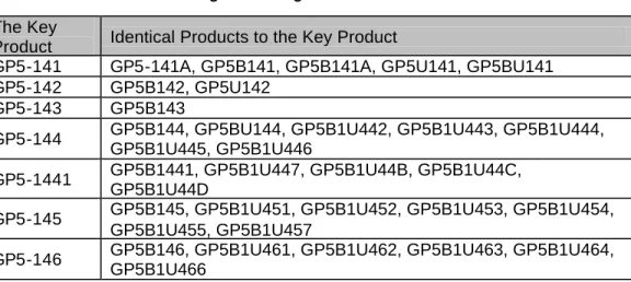
Fig 11-1 shows the target RAID cards.
Fig 11-1 Target RAID Card The Key
Product Identical Products to the Key Product
GP5-141 GP5-141A, GP5B141, GP5B141A, GP5U141, GP5BU141 GP5-142 GP5B142, GP5U142
GP5-143 GP5B143
GP5-144 GP5B144, GP5BU144, GP5B1U442, GP5B1U443, GP5B1U444, GP5B1U445, GP5B1U446
GP5-1441 GP5B1441, GP5B1U447, GP5B1U44B, GP5B1U44C, GP5B1U44D
GP5-145 GP5B145, GP5B1U451, GP5B1U452, GP5B1U453, GP5B1U454, GP5B1U455, GP5B1U457
GP5-146 GP5B146, GP5B1U461, GP5B1U462, GP5B1U463, GP5B1U464, GP5B1U466
16/23
11.2 Target/New Firmware Version
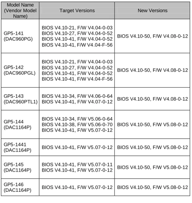
Fig. 11-2 shows the target BIOS/Firmware versions and the new BIOS/Firmware versions.
Fig. 11-2 Target BIOS/Firmware and New BIOS/Firmware Model Name
(Vendor Model Name)
Target Versions New Versions
GP5-141 (DAC960PG) BIOS V4.10-21, F/W V4.04-0-03 BIOS V4.10-27, F/W V4.04-0-52 BIOS V4.10-41, F/W V4.04-0-52 BIOS V4.10-41, F/W V4.04-F-56 BIOS V4.10-50, F/W V4.08-0-12 GP5-142 (DAC960PGL) BIOS V4.10-21, F/W V4.04-0-03 BIOS V4.10-27, F/W V4.04-0-52 BIOS V4.10-41, F/W V4.04-0-52 BIOS V4.10-41, F/W V4.04-F-56 BIOS V4.10-50, F/W V4.08-0-12 GP5-143 (DAC960PTL1) BIOS V4.10-34, F/W V4.06-0-64 BIOS V4.10-41, F/W V4.07-0-12 BIOS V4.10-50, F/W V4.08-0-12 GP5-144 (DAC1164P) BIOS V4.10-34, F/W V5.06-0-64 BIOS V4.10-38, F/W V5.06-0-70 BIOS V4.10-41, F/W V5.07-0-12 BIOS V4.10-50, F/W V5.08-0-12 GP5-1441
(DAC1164P) BIOS V4.10-41, F/W V5.07-0-12 BIOS V4.10-50, F/W V5.08-0-12
GP5-145 (DAC1164P)
BIOS V4.10-41, F/W V5.07-0-11
BIOS V4.10-41, F/W V5.07-0-12 BIOS V4.10-50, F/W V5.08-0-12
GP5-146
17/23
11.3 Firmware Change History
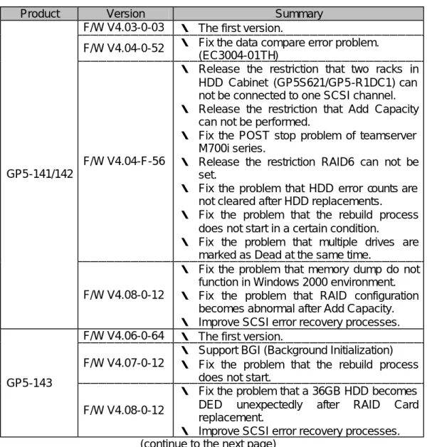
Fig. 11-3 shows the firmware change histories.
Fig. 11-3 Firmware Change History
Product Version Summary
F/W V4.03-0-03 ・ The first version.
F/W V4.04-0-52 ・ Fix the data compare error problem. (EC3004-01TH)
F/W V4.04-F-56
・ Release the restriction that two racks in HDD Cabinet (GP5S621/GP5-R1DC1) can not be connected to one SCSI channel. ・ Release the restriction that Add Capacity
can not be performed.
・ Fix the POST stop problem of teamserver M700i series.
・ Release the restriction RAID6 can not be set.
・ Fix the problem that HDD error counts are not cleared after HDD replacements. ・ Fix the problem that the rebuild process
does not start in a certain condition.
・ Fix the problem that multiple drives are marked as Dead at the same time.
GP5-141/142
F/W V4.08-0-12
・ Fix the problem that memory dump do not function in Windows 2000 environment. ・ Fix the problem that RAID configuration
becomes abnormal after Add Capacity. ・ Improve SCSI error recovery processes. F/W V4.06-0-64 ・ The first version.
F/W V4.07-0-12
・ Support BGI (Background Initialization) ・ Fix the problem that the rebuild process
does not start. GP5-143
F/W V4.08-0-12
・ Fix the problem that a 36GB HDD becomes DED unexpectedly after RAID Card replacement.
・ Improve SCSI error recovery processes. (continue to the next page)
18/23
(continue from the previous page)
Product Version Summary
F/W V5.06-0-64 ・ The first version.
F/W V5.06-0-70
・ Release the restriction that Write Back can not be set.
・ Fix the problem that RAID Card does not function after quick power cycle.
F/W V5.07-0-11
・ Support of BGI (Background Initialization. ・ Fix the problem that the rebuild process
does not start.
F/W V5.07-0-12 ・ Fix the problem DACDIAG SCSI Cable Test outputs Fail unexpectedly.
GP5-144 GP5-1441 GP5-145 GP5-146
F/W V5.08-0-12
・ Fix the problem that a 36GB HDD becomes DED unexpectedly after RAID Card replacement.
・ Fix the problem that BIOS detect timeout in POST, when 21 or more drives are connected to a RAID Card.
19/23
12.
Accessories
Following parts are necessary for this firmware update procedure.
12.1 EC Parts
Check if following 3 parts are packaged in this EC kit.
The Floppy Disk (FD) can be used for multiple systems repeatedly. Since the 100 pieces of version stickers are packaged, this EC kit can be used for 100 systems.
□ Document
Firmware Update Procedure for GP5-141∼146 (This document) □ Floppy Disk
GP5-141/142/143 Firmware V4.08-0-12 GP5-144/145/146 Firmware V5.08-0-12 □ Version Sticker
100 pieces of sticker marked as ‘06’.
12.2 Other Parts
Following 2 parts are necessary additionally. If you use customer’s parts, notify it to the customer previously.
□ MS-DOS Startup Medium
Any of following parts which are attached to servers is necessary for MS-DOS startup.
・CD-ROM ‘Server Wizard’ ・FD ‘System Setup Disk #2’
・FD ‘System Configuration Disk #2’ □ DACCF Medium
Any of following parts which are attached to RAID cards is necessary for DACCF startup.
・FD ‘GP5-143/144/145/146 DACCF Utilities’ ・FD ‘GP5-141/142 DACCF Utility’
20/23
13.
Identification of Target RAID Card
Check below message during the POST process and compare it to the target firmware version in Fig. 11-2. Check the message multiple times, if multiple RAID cards are mounted in a server. You need to apply this firmware update procedure, if one or more target RAID card exists in the multiple RAID cards.
DACxxxxx Firmware Version x.xx-x-xx
14.
Before the Firmware Update
Before the firmware update procedure, please check following.
14.1 Start Monitoring Function Setting of RAS Assist Service
If the RAS Assist Service is installed to the system and the Start Monitoring Function settings in the software are enabled, power cycles or system resets may happen unexpectedly during MS-DOS processes including the firmware update process. Set all of the Start Monitoring Function settings as Disabled prior to this firmware update procedure and set them again to original after the procedure in order to avoid the unexpected operations.
See the User Guide of servers for more details of the RAS Assist Service and the Start Monitoring Functions settings.
14.2 Ban on System Reset and Power Supply Cut
RAID Card hardware may break down, if the power supply of the server is cut or if a system reset is performed during the firmware update process. Don’t cut the power supply of the server nor perform a system reset during the firmware update process.
In particular, pay attention to the setting shown at ‘14.1 Start Monitoring Function Setting of RAS Assist Service’.
14.3 Drive Status
Check the statuses of all hard disk drives with DACADM (Drive Information) or DACCF (Define Pack of View/Update Configuration). All drives must be ‘ONL’ or ‘SBY’ before this firmware update procedure. If any other statuses were found, please recover the array prior to the procedure.
14.4 System Seizing-acknowledgment
Perform a system shut down, cut the power supply of the system, re-start Windows NT/2000 once and confirm that the OS operates normally, prior to the firmware update procedure. Even if any of system files which are not used except the system startup are corrupted, the system operates normally without detecting the corrupted files. If the system were not to startup properly because of the corrupted system file, the root-cause of the problem can not be isolated whether the problem happened because of the firmware update or not. So the purpose of this performance is to make clear the root-cause of the problem which happened after the firmware update procedure.
It is recommended that this is performed in front of the customer.
14.5 Backup of RAID Configuration
It is necessary to save the RAID configuration just before the firmware update procedure for the unexpected problems which may happen after the firmware update. Select ’Tools’
21/23
and ‘Backup Configuration’ from the DACCF main menu in this order and save the current configuration to a file in a floppy disk.
14.6 MS-DOS Environment
The firmware update utility does not work properly in the MS-DOS environment to which HIMEM.SYS or EMM386.EXE are installed. It is necessary to start MS-DOS with the proper procedure shown in this document.
15.
Firmware Update Procedure
Following is the firmware update procedure. See again ‘14. Before the Firmware Update’ for confirmation prior to this procedure.
15.1 MS-DOS Start Procedure
Start MS-DOS with any of below two ways certainly.
15.1.a Start MS-DOS with the Server Wizard CD-ROM
(1) Install Server Wizard CD-ROM in the CD-ROM drive and cut the power supply of the server. Proper shut down process must be performed before the power cut. (2) Power on the server.
(3) Select ‘Basic (BIOS Environment Support Tools)’ in ‘MS-DOS Startup Menu’. (4) Proceed to ‘15.2 Firmware Update Procedure‘, if MS-DOS prompt appeared. 15.1.b Start MS-DOS with a FD
(1) Cut the power supply of the server. Proper shut down process must be performed before the power cut.
(2) Insert ‘System Setup Disk #2’ or ‘System Configuration Disk #2’ to the floppy disk drive of the server.
(3) Power on the server.
(4) Keep pushing [Shift] key, when the message ‘Starting MS-DOS’ is displayed (or before the message).
(5) Stop pushing the [Shift] key and proceed to ‘15.2 Firmware Update Procedure‘, if MS-DOS prompt appeared.
Reference
AUTOEXEC.BAT and CONFIG.SYS are bypassed and any device drivers such as HIMEM.SYS are not installed to MS-DOS, if you keep pushing the [Shift] key. If the [Shift] key is recognized properly, the setup menu does not start and MS-DOS prompt is displayed immediately.
22/23
15.2 Firmware Update Procedure
(1) Insert ‘GP5-141/142/143 Firmware V4.08-0-12 GP5-144/145/146 Firmware V5.08-0-12’ of EC parts to the floppy disk drive of the server. If you started MS-DOS with a FD, replace the FD to the FD of the EC parts.
(2) If you started MS-DOS with the Server Wizard CD-ROM, type below and hit [Enter] key to change the current directory to the root directory of the floppy disk drive. If you start MS-DOS with a FD, you don’t have to do this.
B: (and hit [Enter] key)
(3) Type below and hit [Enter] key. Firmware update starts. The firmware update utility automatically searches for the target RAID cards and automatically update the firmware to proper versions.
UPDATE (and hit [Enter] key)
(4) Following message shows the firmware update completed successfully. Complete.
(5) After the confirmation of the message, remove the mediums from the floppy disk drive and the CD-ROM drive.
(6) Put the version sticker which is marked as ‘06’ on the part of the ISA bracket in order to show that this EC has been already applied to the RAID cards. (The picture is GP5-144.)
Fig. 6-1 Location of the version sticker (7) This ends the firmware update procedure.
Warning!
If unexpected power cycles or unexpected system resets are performed during the firmware update process, the RAID card hardware may break down. Don’t perform such operations during the process.
23/23
16.
Confirmations after the Update
Following is the items of confirmations after the firmware update.
16.1 Confirmation of Firmware Version
Check below message during the POST process and compare it to the new firmware versions in Fig. 11-2. Check the message multiple times, if multiple RAID cards are mounted in a server. The versions must become 4.08-0-12 or 5.08-0-12.
DACxxxxx Firmware Version x.xx-x-xx
16.2 Confirmation of OS Start
Confirm the network OS (Windows 2000 or Windows NT etc.) starts normally.
17.
Others
EC parts can be used for multiple systems repeatedly.
18.
Appendix (Message List)
Following is the outputs of the firmware update utility. □ Complete.
Firmware update completed successfully. □ Firmware version is equal to index data.
The latest firmware is already applied to the object RAID card. □ Abnormal Ended.
Firmware update ended abnormally. See the messages above this message and perform proper actions.
□ Channel = xx, Target = yy, Dead Drive detected.
SCSI channel #xx, SCSI target ID #yy is DED. Replace the DED drive and rebuild it before the firmware update.
□ Standby/background, rebuild/check in progress.
Rebuild is in progress. Perform the firmware update after the rebuild process completion.
Reference
In Windows 2000 environment, a message which shows a new hardware was detected and instructs you to re-start the system may appear at the first startup of the system after the firmware update. Follow the message and re-start the system in this case.