Describing and verifying integrated services of home network systems
14
0
0
全文
(2) Describing and Verifying Integrated Services of Home Network Systems Pattara Leelaprute1 , Masahide Nakamura2 , Tatsuhiro Tsuchiya1 , Ken-ichi Matsumoto2 , Tohru Kikuno1 1 Graduate School of Information Science and Technology, Osaka University, Japan {pattara, t-tutiya, kikuno}@ist.osaka-u.ac.jp 2 Graduate School of Information Science, Nara Institute of Science and Technology, Japan {masa-n, matumoto}@is.aist-nara.ac.jp Abstract This paper presents a framework to specify and verify integrated services of a home network system (HNS). We first develop a modeling language to describe the HNS and the integrated services. Complementing our previous work, the language captures each appliance as an object consisting of properties and methods, encapsulating the underlying protocols and platforms. We then present a method that verifies the integrated services with symbolic model checking, by translating the proposed language into the SMV (Symbolic Model Verifier) language. Thus, it is possible to validate if the integrated service is specified as intended, automatically and exhaustively. Using the proposed framework, service developers can effectively detect design flaws in a single integrated service, as well as feature interactions among multiple services, in early stages of service development. keywords: home network system, integrated services, model checking, SMV, V&V technique. 1. Introduction With the emerging technologies in ubiquitous computing, general household appliances are being equipped with smart processors and network interfaces. Home appliances, such as TVs, DVDs, air-conditioners, refrigerators, ventilators, even lights and windows, are connected to LAN at home, comprising a home network system (HNS, for short). A major challenge of the HNS lies in integrating features of different appliances via network [12]. The integration would implement various value-added services (called HNS integrated services), which provide a more comfortable and convenient living environment for home users. For instance, integrating an air-conditioner, a window (controller), a ventilator and thermometers would implement an HVAC (heating, ventilation and air-conditioning) service [3]. This integrated service achieves energy-saving air-conditioning by automatically controlling the ventilator and the window, according to the current temperature inside/outside the room. Recently, several HNS protocols have been being standardized (e.g., UPnP [14] for AV appliances, ECHONET. [3] for white goods). However, these protocols only prescribe how each appliance communicates with others via network. How to integrate features of different appliances is beyond their scope. Thus, there are still many open issues in developing the HNS integrated services efficiently. Especially, methods in early stages of development, including modeling, design and validation, have not been widely studied. Lack of these methods may cause unreliable and low-quality service design, which forces service developers to directly implement services in an ad-hoc and timeconsuming manner. To cope with the problem, this paper presents a formal method for specifying and validating the HNS integrated services, which helps developers in early stages of service development. The proposed framework consists of two parts. The first part is a description method of the HNS and integrated services. Based on our previous work [9], we establish an object-oriented model of the HNS. In the model, each appliance (or environment) is represented by an object, consisting of properties and methods. For each appliance object, properties characterize the current (internal) state, while methods represents features (i.e., APIs) simply characterized by a pair of pre and post conditions. Then, we construct HNS integrated services by combining the methods provided by different appliance objects. To specify the integrated services, we propose a modeling language. The language allows sequential execution, branches and loop. Through some practical examples, we show the language is sufficient enough to specify complex integrated services. In the second part, we present a method that validates the integrated services with symbolic model checking [7]. Specifically, we develop a method translating an integrated service specified in the proposed language into the wellknown SMV (Symbolic Model Verifier) language. Once translated, the SMV tool automatically and exhaustively verifies the integrated service against any properties specified in CTL (Computational Tree Logic). Thus, we can effectively detect design flaws in integrated services..
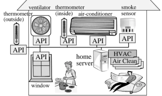
(3) 2. Home Network System A home network system (HNS) consists of one or more networked appliances connected to a local area network at home. In general, each HNS appliance has a set of device control interfaces (i.e, APIs), by which the users or external software agents can control the appliance via the network. To handle API calls, an appliance is usually equipped with at least a processor, a storage and a network interface. The communication among the appliances is performed with an underlying HNS protocol. Several HNS protocols are currently being standardized, such as UPnP [14], ECHONET [3], Jini [8] and HAVi [5]. These HNS protocols prescribe a set of network-level agreements including; address setup, advertisement, message formats. In this paper, we discuss a generic framework independent of any specific HNS protocol. Hence, we assume that each appliance has a certain mechanism (e.g., middleware or gateway) to handle a HNS protocol. The main advantage of the HNS lies in integrating features of different appliances flexibly, which yields valueadded services. We refer to such service as HNS integrated services. For the sake of discussion, consider a HNS consisting of the following networked appliances: an airconditioner, a ventilator, a window, two thermometers and a smoke sensor. HVAC Service (Cooling mode): HVAC achieves energy-saving air-conditioning of a room based on a given temperature setting. If the room is hotter than the temperature setting, it operates the air-conditioner in the cooling mode. To efficiently cool down the room, if the room temperature is hotter than the outside, the ventilator is also turned on to provide fresh outside air. In this case the ventilator will be kept working until the room temperature reaches the outside temperature. If the room temperature is below the temperature setting, on the other hand, HVAC has the air-conditioner operate in the fan mode. Air Cleaning Service: Air Cleaning Service cleans the air in the room, cooperating with the smoke sensor. When the smoke sensor detects the smoke (caused by tobacco, cooking, or fire), the service automatically opens the window and turns on the ventilator. When the air is cleaned, the window and the ventilator are shut down. The HNS integrated services are usually implemented as software applications that activate different HNS appliances in a pre-defined manner. These applications could be installed in a centralized home server [12], or could be distributed in appliances themselves [10]. Figure 1 shows an example HNS, where integrated services are deployed in the home server. Although several standards for the appliance integration are currently being developed (e.g., OSGi [12], DLNA [2] and DHF [6]), they are still in the architecture level. Design and implementation of concrete inte-. ventilator thermometer (inside) air-conditioner thermometer (outside). API. API. API. API API. home server. smoke sensor. API HVAC Air Clean. window. Figure 1. Example Home Network System grated services (i.e., software applications) are completely up to individual service vendors.. 3. Object-Oriented Model for HNS [9] 3.1. HNS Model Appliance Object In [9], we modeled each appliance as an object, consisting of properties and methods. The properties are attributes that characterize the internal states of the appliance. Each property has a type determining allowable values of the property. The methods represent the APIs (i.e., device control interfaces) that refer or update the properties. Since the internal implementation of the APIs is usually encapsulated in the appliance, we characterize each method simply by a pair of a pre-condition and a post-condition. Definition 1 (Appliance) A networked home appliance d is defined as a quad tuple d = (P d , Md , P red , P ostd ), where • Pd = {p1 , ..., pn } is a set of all properties of d. • Md = {m1 , ..., mk } is a set of all methods of d. • P red is a pre-condition function which maps each method mi ∈ Md to a logical formula over P d . mi can be executed only when P re d (mi ) is true. • P ostd is a post-condition function which maps each method mi ∈ Md to a logical formula [p 1 = a1 ∧ ... ∧ pn = an ], where ai is a value over the type of p i . If mi is executed, the value of p i becomes equal to a i and the other properties that do not appear in the formula keep their values unchanged. A property p ∈ Pd (or a method m ∈ M d ) of an appliance d is denoted by d.p (or d.m, respectively). Environment Object Executing appliance APIs (i.e., methods) may often give certain impacts on the environment of the home, such as temperature, brightness, sound, motion, smoke, etc. An environment object is a global object consisting of properties, which is indirectly referred (read) or updated (written) by the appliance methods..
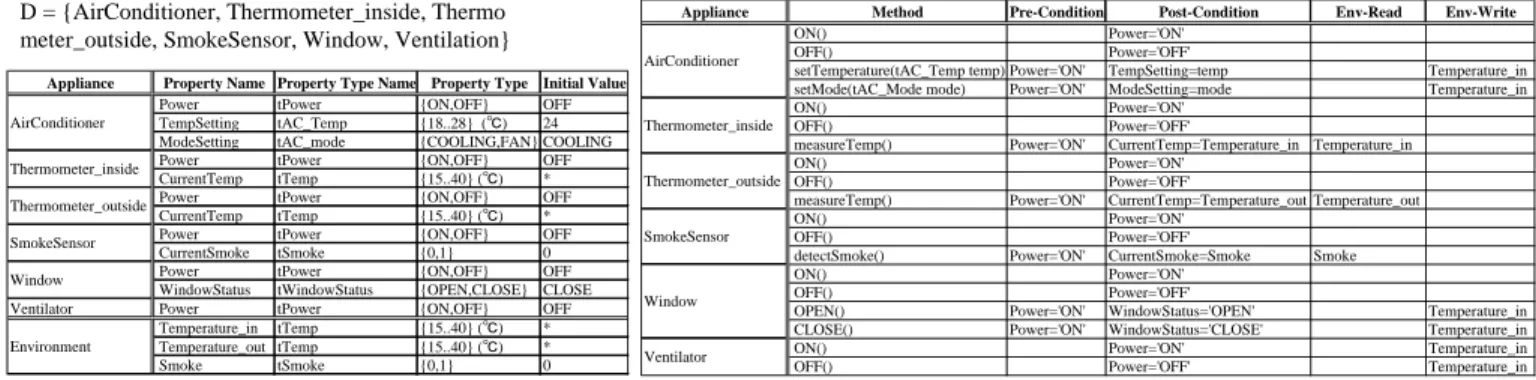
(4) HNS = (D,e), where D = {AirConditioner, Thermometer_inside, Thermo meter_outside, SmokeSensor, Window, Ventilation} Appliance. Property Name Power AirConditioner TempSetting ModeSetting Power Thermometer_inside CurrentTemp Power Thermometer_outside CurrentTemp Power SmokeSensor CurrentSmoke Power Window WindowStatus Ventilator Power Temperature_in Environment Temperature_out Smoke. Appliance. Property Type Name Property Type Initial Value tPower {ON,OFF} OFF 24 tAC_Temp {18..28} (℃) tAC_mode {COOLING,FAN} COOLING tPower {ON,OFF} OFF * tTemp {15..40} (℃) tPower {ON,OFF} OFF * tTemp {15..40} (℃) tPower {ON,OFF} OFF tSmoke {0,1} 0 tPower {ON,OFF} OFF tWindowStatus {OPEN,CLOSE} CLOSE tPower {ON,OFF} OFF tTemp {15..40} (℃) * * tTemp {15..40} (℃) tSmoke {0,1} 0. Method Pre-Condition Post-Condition Env-Read ON() Power='ON' OFF() Power='OFF' AirConditioner setTemperature(tAC_Temp temp) Power='ON' TempSetting=temp setMode(tAC_Mode mode) Power='ON' ModeSetting=mode ON() Power='ON' Thermometer_inside OFF() Power='OFF' measureTemp() Power='ON' CurrentTemp=Temperature_in Temperature_in ON() Power='ON' Thermometer_outside OFF() Power='OFF' measureTemp() Power='ON' CurrentTemp=Temperature_out Temperature_out ON() Power='ON' SmokeSensor OFF() Power='OFF' detectSmoke() Power='ON' CurrentSmoke=Smoke Smoke ON() Power='ON' OFF() Power='OFF' Window OPEN() Power='ON' WindowStatus='OPEN' CLOSE() Power='ON' WindowStatus='CLOSE' ON() Power='ON' Ventilator OFF() Power='OFF'. (a) Appliance/Environment Properties. Env-Write. Temperature_in Temperature_in. Temperature_in Temperature_in Temperature_in Temperature_in. (b) Appliance Methods. Figure 2. Model of Example HNS Definition 2 (Environment) Let D = {d1 , d2 , ..., dk } be a set of all appliances deployed in the HNS. Also, let M = ∪di ∈D Mdi be a set of methods of all appliances. Then, an environment e is defined as a tuple e = (P e , Re , We ), where • Pe is a set of all environment properties. • Re is an environment read function M → 2 Pe , which maps each method m ∈ M into a set of environment properties that are read by m. • We is the environment write function M → 2 Pe , which maps each method m ∈ M into a set of environment properties that are written by m. Consequently, a HNS is defined by a set of appliance objects and an environment object. Definition 3 (Home Network System) A home work system is defined as HN S = (D, e), where. net-. • D = {d1 , d2 , ..., dn } is a set of appliances. • e = (Pe , Re , We ) is an environment where the HNS is deployed. Figure 2 shows a model of the example HNS in Section 2. Figure 2(a) lists properties and their types for each appliance (or environment). For instance, AirConditioner has three properties: Power, TempSetting and ModeSetting. The type of Power is {ON,OFF}, saying that the value of Power is either ’ON’ or ’OFF’. For convenience, each type has a name prefixed by t. Figure 2(b) shows appliance methods, each of which is characterized by pre/post conditions and environment properties to read/write. For example, take a method AirConditioner.setMode(tAC mode mode). Its pre-condition says that the method can be executed only when the air-conditioner is on (Power=’ON’). The method has a formal parameter mode, to which a certain value (over tAC mode) is supposed to be assigned when invoked. AirConditioner.setMode(’COOLING’);). (e.g., When the method executed, property ModeSetting is updated to the value of mode, according to its post-condition (ModeSetting=mode). Invocation of the method writes an environment property Temperature in, meaning that setting the air-con mode would change the temperature inside room. In Figure 2, * denotes a “don’t care”.. 3.2. Integrated Service Scenarios In [9], we defined an integrated service as a scenario consisting of methods invocations. Definition 4 (HNS Integrated Service Scenario) Let HN S = (D, e) be a given HNS. Then, a sequence of any appliance methods ss i = di1 .mi1 ; di2 .mi2 ; ...; dik .mik ; (dij ∈ D, mij ∈ Mdij and “;” denotes a sequential execution) is called an HNS integrated service scenario. For instance, consider the HNS model in Figure 2. Then, the following sequence of method invocations would implement LeavingHome service, which shutdowns all appliances in the HNS before leaving home. Leaving Home Service: AirConditioner.OFF(); Thermometer_inside.OFF(); Thermometer_outside.OFF(); Window.CLOSE(); Window.OFF(); Ventilator.OFF();. 3.3. Limitations of the Previous Model Although the above definitions give a reasonable framework to formalize a HNS, there are still several limitations from a practical viewpoint. Limitations in Service Description: Since each integrated service is defined as a scenario, it is difficult to describe services containing branches or loops. Also, there is no explicit way to describe when or by whom the service is ter-.
(5) minated. Return values and arguments of the methods are not explicitly defined. No (local) variables can be used. Moreover, computer-aided analysis cannot be directly performed, since description language for a HNS or services is not yet determined. Due to these limitations, the previous framework can manage only cheap and simple services, like LeavingHome. Indeed, it is quite hard to describe more sophisticated services, like HVAC and Air-Cleaning services presented in Section 2 with only this framework, since the services contain branches for the conditions and loops for the environmental monitoring. Limitations in Service Analysis: Since the model was originally designated to analyze a specific problem, i.e., feature interactions among integrated services, analysis of any other properties was beyond the scope. Preferably however, more general properties other than the feature interactions should be analyzed within the model, to take full advantages of the formalization.. 4. Proposed Service Description Language 4.1. System Description The system description follows almost exactly the HNS model defined in Section 3.1, except that for each appliance method, return type and return value are specified explicitly. A HNS is described in the following format. A sentence begins with # is a comment, and capital words (like SYSTEM, TYPEDEF, etc.) denote keywords. SYSTEM HNS_name { TYPEDEF # Type definition type_name1 type1; type_name2 type2; : # Environment definition ENVIRONMENT env_name { PROPERTY # Environment properties declaration type_name1 env_property1 [:= init_val]; type_name2 env_property2 [:= init_val]; : } # Appliance definition APPLIANCE appliance_name1 { PROPERTY # Appliance properties declaration type_name1 app_property1 [:= init_val]; type_name2 app_property2 [:= init_val]; : METHOD # Method definition : } APPLIANCE appliance_name2 { : } : }. The system is named at the top nesting level following SYSTEM keyword. The body of the system consists of three sections: TYPEDEF section, ENVIRONMENT section, and APPLIANCE section.. Type Definition TYPEDEF section declares types commonly used in the system. In the proposed language, we allow only three types: Boolean (i.e., {true,false}), integer, or enumeration. An integer type is specified by upper and lower bounds, e.g., {1..5}. An enumeration type is defined by enumerating concrete elements, e.g., {on,off}. Every type can be named by an identifier, e.g., tPower {on, off}. The scope of the type name covers the entire system description. Environment Definition ENVIRONMENT section define an environment object. In our HNS model, an environment consists of only environment properties. For each property, an identifier and its type declared in the TYPEDEF section are specified. Optionally, one can specify the initial value of the property with the assignment operator (:=). Appliance Definition All appliances deployed in the HNS are declared in multiple APPLIANCE sections (blocks), each of which defines an appliance object. An APPLIANCE block comprises of definitions of properties and methods of the appliance. The definition of the appliance properties is specified in the same way as in the ENVIRONMENT section. The methods are designated in a METHOD subsection, whose format is as follows: METHOD # method definition return_type1 method_name1([type_name formal_param]*){ PRE pre_condition; POST post_condition; ENV_R env_name.property_name; ENV_W env_name.property_name; RETURN return_value; } return_type2 method_name2(...) { : } :. A method is defined as a name and its return type. The return type must be a type declared in the TYPEDEF or void. A method can have one or more formal parameters (separated by ’,’), each of which is declared by type and name. The body of the method contains pre/post conditions, environment read/write, and the return value. To specify a logical formula for the pre(or post) condition, the properties, the formal parameters, and ordinary unary and binary operators (+, -, =, <, >, <=, >=, !=, !, &, |) can be used. ENV R (or ENV W) enumerates environment properties read (or written, respectively) by the method. RETURN specifies the value to be returned, which can be specified by a property or an expression (e.g., AC Temp + 1).. 4.2. Service Description The service description presented here significantly extends the expressivity of the scenario-based definition (in Definition 4) of integrated services. Specifically, we introduce (a) WHILE and IF statements for complex control flows, (b) local variables for storing temporal data, and (c).
(6) pseudo functions to abstract events. The service description adopts the following format. DEPLOYED_SYSTEM HNS_name; SERVICE service_name1([type_name formal_param]*){ # Variable declaration VAR type_name local_var1 [:=initial_value]; type_name local_var2 [:=initial_value]; : # Appliance declaration APPLIANCE appliance1, appliance2,..; CONTENT statement1; statement2; :. # service content. } SERVICE service_name2(type_name formal_para_name){ : }. The keyword DEPLOYED SYSTEM is to specify a HNS where the services are deployed. It imports a system description designated by HNS name. The integrated services are defined by one or more blocks of SERVICE. Similarly to the appliance method, a service can have formal parameters, supposing that an actual value is passed to each parameter when a user agent invokes the service. Variable and Appliance Declarations A service can use local variables declared in VAR subsection. The declaration is done in the same way as properties in system description. Allowable types are either Boolean, integer, or enumeration. The scope of the variables is only within the service. APPLIANCE subsection designates appliance objects used in the service. The appliances must be the ones defined in the imported system description. Service Content CONTENT subsection describes the body of the service, which consists of one or more statements. Basically, the statements are sequentially executed one-byone from top to bottom, as in the ordinary programming language. The syntax of the statements is given in a BNF form as follows. statement:: invocation_statement | assignment_statement | if_statement | while_statement | { compound_statement } invocation_statement:: invocation ; invocation:: appliance_name.method_name(arg_list) | pseudo_function arg_list:: expression | expression, arg_list pseudo_function:: end() | exit() assignment_statement:: local_var := expression if_statement:: if (Boolean_expression) statement | if (Boolean_expression) statement else statement while_statement:: while (Boolean_expression) statement compound_statement:: statement | compound_statement statement. • invocation statement refers to a statement that invokes an appliance method (or a pseudo function, discussed later). The method invocation is executable when its precondition is satisfied. As seen in Section 3.2, invocation of an appliance method is a primitive construct of an integrated service. Invocation of an appliance method can take actual parameters as a list of expressions. Due to limited space, we omit the syntax of expression. In the proposed language, an expression is constructed by operators given in Section 4.1. As for operands, local variables, properties, constants and invocation can be used. • pseudo function is a meta function to model an abstract event in the service. Two types of functions are prepared: end() and exit(). end() is supposed to return true (1) when the user terminates the service (e.g., with a termination signal from the user agent). exit() models a system call that the system terminates the service. These are for the developer to specify explicitly when or by whom the service is terminated. The pseudo functions are always executable. • assignment statement set the evaluated value of an expression to a local variable in the same type. Note that an appliance (or environment) property cannot come at the left-hand side, since the properties cannot be updated directly, and should be accessed via appliance methods. • if statement specifies a conditional branch. If Boolean expression is evaluated to be true, then the first statement is executed next. If not, the second statement (in ELSE-clause) is chosen to execute. The Boolean expression is an expression whose result takes true (1) or false (0). • while statement specifies a loop. The statement is repeatedly executed while Boolean expression is true. • compound statement represents a block of multiple statements.. 5. Translating Service Description for Symbolic Model Checking 5.1. Symbolic Model Checking and SMV Model checking is the process of exploring a finite state space to determine whether or not a given property holds [1]. The major problem of model checking is that the state spaces arising from practical problems are often extremely large. A promising approach to this problem is the use of symbolic representations of the state space; that is, Boolean functions represented by Ordered Binary Decision Diagrams (OBDDs) are used to represent the state space, instead of explicit adjacency-lists. This can reduce dramatically the memory and time required because OBDDs rep-.
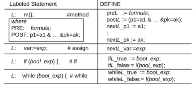
(7) resent many frequently occurring Boolean functions very compactly. SMV is a software tool that implements symbolic model checking [7]. To use SMV to verify a system, the system needs to be described as an SMV program in the SMV language. An SMV program is divided into one or more modules, each of which specifies a finite state machine. The interaction between concurrently executing modules is specified in the main module. In particular, if concurrently executing modules are defined using the process keyword, these modules use an interleaving semantics, in which only one process transitions at each step. Each module contains variable declarations to determine its state space and descriptions of the initial state and transition relation of the machine. Variable declarations are preceded by the keyword VAR. The type associated with a variable can be Boolean or an enumerated type. The transition relation is described by a collection of parallel assignments to the next version of the variables. Assignments of initial values and next values to the variables are preceded by the keyword ASSIGN. Initial states are assigned by specifying the initial values of the variables using the expression init(x), where x is a variable. The expression next(x) is used to refer to the variable x in the next state The correctness property to be verified is specified in an SMV program as a formula in CTL (Computational Tree Logic), under the keyword SPEC. CTL is a well-known temporal logic. SMV verifies whether all possible initial states satisfy the property or not.. 5.2. Compiling Service Description This subsection presents a method to compile an integrated service described in the proposed language into an SMV program. Our language basically describes each service as a sequential program, where statements are executed sequentially one-by-one according to given control flows. On the other hand, the SMV describes the system based on the transition relations only. Hence, the key is how to achieve the original control flow in the target SMV program. To achieve the compilation, we take a similar idea discussed in [1](Section 2). We assume that a service description Ser and the corresponding system description Sys are given as inputs. The output is an SMV program smv that simulates Ser. Step 0: Preliminary We define a main module in smv. For every appliance (or environment) property A.p in Sys, we define A.p as a variable A p in VAR section of smv, with the appropriate type. Also, we assign the initial value to A p in ASSIGN section of smv. For every environment property ep, define its next value as an arbitrary value of its type, since the environment changes arbitrarily so that the system cannot predict it. For instance, for the system given in Figure 2, the main module would be:. begin_dummy; statement1; statement2; : end_dummy:. (a) Dummies for a whole service. : if (cond) { statements; if_dummy; } else { statements; } ifend_dummy: : (b) Dummies for a if-statement. : while_dummy; while (cond) { statements; whileend_dummy; } : (c) Dummies for a while-statement. Figure 3. Inserting Dummy Statements MODULE main VAR AC_Pwr:{ON,OFF}; --Aircon.Power(App prop.) : ENV_Tout:{15..40}; --Temp. outside (Env prop.) : ASSIGN init(AC_Pwr):=OFF; : next(ENV_Tout):={15..40}; -- Changes arbitrarily :. For each SERVICE svc declared in Ser, we perform from Step 1 to Step 5. Step 1: Making a Module for the Service We define svc as a module svc in smv. The formal parameters of svc and all properties referred in svc are specified as the formal parameters of svc. Then, svc is included as process in the main module. Also, we declare local variables of svc in VAR section as they are. For instance, HVAC service could be: MODULE main VAR HVAC1:process HVAC(26, AC_Pwr,...ENV_Tout): MODULE HVAC(usr_temp, AC_Pwr,...,ENV_Tout) VAR Ti_temp: {15..40}; -- local variable. : ASSIGN init(Ti_temp) := 40; :. Step 2: Labeling Statements For every statement in CONTENT of svc, we attach a unique label to achieve a consistent control flow in smv. First, we insert dummy statements in svc, as shown in Figure 3. These dummies have no effect, but for specifying special points of control. Next, we extract each method invocation from expressions. For each method invocation m() in an expression e, we replace m() by the return value of m(). Then, we add m(); immediately before e. For instance, var:=A.m1()+B.m2()+c; is translated into three statements below: A.m1(); B.m2(); var: = RET(A.m1()) + RET(B.m2()) + c;. For the resultant statements, we put sequence numbers from begin dummy; to end dummy;, as the unique labels. By convention, we assume that begin dummy; and.
(8) Labeled Statement. DEFINE. L: m(); #method where PRE: formula; POST: p1=a1 & … &pk=ak;. preL := formula; postL := (p1=a1 & … &pk=ak); nextL_p1 := a1; : nextL_pk := ak;. L:. var:=exp;. nextL_var:=exp;. L:. if (bool_exp) {. L:. while (bool_exp) { # while. # assign # if. ifL_true := bool_exp; ifL_false:= !(bool_exp); whileL_true := bool_exp; whileL_false:= !(bool_exp);. Labeled Statement L: m(); L: if (cond) { L: L:. if_dummy; while (cond) {. L: L: L: L:. whileend_dummy ; exit(); end_dummy ; any_other_statement ;. ASSIGN next(pc) : = (pc = L) & preL : L+1 ; (pc = L) & ifL_true : L+1; (pc = L) & ifL_false : label(if_dummy)+1; (pc = L) : label(ifend_dummy); (pc = L) & whileL_true : L+1; (pc = L) & whileL_false: label(whileend_dummy)+1; (pc = L) : label(while_dummy); (pc = L) : label(end_dummy); (pc = L) : label(begin_dummy); (pc = L) : L+1;. Table 1. Condition Conversion Rules. Table 2. Program Counter Update Rules. end dummy are labeled by 0: and max:, respectively. In. dition of m() are updated to the next values, which defines a transition relation of the system. Hence, for each property p, we need to identify when p is updated by which statement. Fortunately, we can easily specify the transition relation by consulting DEFINE section generated in Step 3. For a property p, if DEFINE contains nextL p:=a;, it means that p is updated by the L-th statement, which is a method invocation m(). Thus, p can be updated when pc=L and the pre-condition of m() becomes true. Note that p could be updated in other statements as well. As a result, the next value of p can be defined as:. the following, let label(stm) denote the label (number) of a statement stm. Step 3: Extracting Conditions as Macros For each stm of the labeled statements, we extract conditions from stm, and convert them into DEFINE macros of smv. The rules for the conversion are shown in Table 1, supposing that L = label(stm). The first rule applies when stm is a method invocation. In DEFINE, pre/post conditions are described as they are. Moreover, a value of each property p i is defined as nextL pi, which will be used to specify the next value of p i in Step 5. The second rule is for assignment statement, which specifies the next value of local variable var. The last two rules are for if and while. The rules generate two macros that represent two cases where the condition is true and false. Step 4: Deploying a Program Counter To simulate the control flow of svc, we introduce a variable pc in smv as a program counter. First, we define a local variable pc in the svc module of smv, as VAR pc:{0..max};, and initialize as ASSIGN init(pc):=0;. Suppose that pc = L when smv is currently simulating a L-th statement stm (i.e., label(stm) = L). Then, we want to update pc to an appropriate next value after stm is executed. For this, we present rules to compute the next value of pc in Table 2. The first rule applies when stm is a method invocation m(). In order for m() to be executed, the pre-condition of m() preL (see Table 1) must hold. In this case, the next value of pc will be L+1. When stm is an if-statement (or while-statement), the next value depends on the condition as shown in the second (or fourth) rule. If the condition is false, then stm is set to the label of a dummy statement, so that the execution jumps to an appropriate control point (see Figure 3). Similarly, a jump also occurs when stm is a certain dummy statement. When stm is exit(), pc is set to the last statement, which simulates the end of service. We apply the rules to all the statements, and resultant SMV code would be: ASSIGN next(pc):= case .... esac;. Step 5: Specifying Transition Relations When a method invocation m() occurs, properties specified in the post con-. ASSIGN next(p):= case (pc=L) & preL :nextL_p; --updated by L-th statement : --updated by other statements 1: p; --stay unchanged. esac;. Similarly, we can define the next value of a local variable var, which could be updated by an assignment statement. ASSIGN next(var):= case (pc=L) :nextL_var; --updated by L-th statement : --updated by other statements 1: var; --stay unchanged. esac;. We apply the same procedures to all the properties and local variables defined in svc. Finally, we model the behavior of end() pseudo function. By definition, end() returns true when the user wants to terminate the service. However, the system cannot predict when the termination occurs. So, we abstract the behavior by using non-determinism. We also give a FAIRNESS constraint to prevent end from taking the same value infinitely. VAR end:{0,1}; --Boolean for end() function ASSIGN next(end):= case (pc=L) :{0,1}; --non-determinism in L-th statement 1: end; --stay unchanged. esac; FAIRNESS end=1; --eventually terminates the service FAIRNESS end=0; --eventually continue the service. 6. Verifying Integrated Services Using the proposed language, the HVAC and AirCleaning services in Section 2 can be described (see Appendix A and B for the system and service descriptions) The description is compiled into an SMV pro-.
(9) gram, comprising about 580 lines of code (see Appendix C). Based on the informal descriptions (high-level requirements) presented in Section 2, we derived the following CTL formulas as desirable properties for the services. Properties for HVAC Service: • If the service is started, then the air-conditioner will be eventually turned on. P1: SPEC AG(pc=1 -> AF(Aircon_pw=on )). • If the room temperature exceeds the temperature setting, then the mode of the air-conditioner will be set to the cooling mode. On the other hand, if the temperature is below the temperature setting, then the mode of the air-conditioner will be set to the fan mode. P2:SPEC AG((Ti_temp > user_temp) -> AF(Aircon_setMode=cooling)) P3:SPEC AG(!(Ti_temp > user_temp) -> AF(Aircon_setMode=fan)). • Once the ventilator is turned on, it will be kept operating until the inside temperature reaches the outside temperature. P4: SPEC AG(Ventilation_pw=on ->A[Ventilation_pw =on U !(a.Ti_temp > a.To_temp) ]). Properties for Air-Cleaning Service: • Whenever the sensor device senses smoke, the ventilator will be turned on and the window will be opened. P5: SPEC AG(SmokeSensor_currentSmoke=1 -> AF(Ventilation_pw=on)) P6: SPEC AG(SmokeSensor_currentSmoke=1 -> AF(Window_status=open)). • If the window is opened, then the window will be kept open until the sensor no longer senses smoke. Similarly, once the ventilator is turned on, it will be kept working until no smoke is detected. P7: SPEC AG(Window_status=open -> A[Window_status =open U SmokeSensor_currentSmoke=0]) P8: SPEC AG(Ventilation_pw=on -> A[Ventilation_pw =on U SmokeSensor_currentSmoke=0]). We have verified these properties against individual services using a model checker SMV [13]. As a result, it was automatically proven that the HVAC service successfully conformed to P1 through P4 in all possible reachable states. Also, all properties from P5 through P8 became true for the Air-Cleaning service. The time taken for the verification was 0.59 sec. per each property on the average, with the PC with PentiumM 1.0Ghz (Memory 760MB, WinXP Pro). As a result, it was confirmed quite efficiently that our design of the individual services had no critical design flaw. Interestingly however, the properties P4 and P8 became false when we ran the two services in parallel. The counterexample of P8 told that the ventilation is turned off although there is still smoke. This is because the HVAC turns off the. ventilation, when the room temperature have been below outside. The finding was observed due to a functional conflict among the services, which is well known as the feature interaction problem [4]. Developing a more systematic approach to detecting feature interaction using the model checking will be left to our future research.. 7. Discussion and Concluding Remarks This paper presented a formal framework to verify and validate integrated services of home network systems. Although not presented in the paper, we actually have described various services using the proposed language, such as the ten services presented in [9] and more including a security service and a power-saving service. Thus, we believe that the proposed language is expressive enough to describe practical services. Also, the proposed language enables a compact modeling independent of the underlying HNS protocols or specific platform. Hence, it could be helpful for developers to conduct a platform-independent modeling (PIM) of the MDA [11]. It is also interesting to develop a method to convert the proposed language into platform-specific workflow languages such as BPEL4WS.. References [1] E. M. Clarke, O. Grumberg, and D. A. Peled, Model Checking, MIT Press, 1999. [2] Digital Living Network Alliance http://www.dlna.org/. [3] ECHONET Consortium- http://www.echonet.gr.jp/ [4] “Feature Interaction in Telecommunications and Software Systems”, Vol. I-VIII, IOS Press, 1992-2005. [5] HAVi - http://www.havi.org/ [6] ITU-T Recommendation J.190, “Architecture of Media HomeNet that supports cable-based services”, 2002. [7] K. L. McMillan, “Symbolic Model Checking”. Kluwer Academic Publishers, 1993. [8] Jini - http://www.jini.org/ [9] M. Nakamura, H. Igaki, K. Matsumoto, “Feature Interactions in Integrated Services of Networked Home Appliance”, Proc. of Int’l. Conf. on Feature Interactions in Telecommunication Networks and Distributed Systems (ICFI’05), pp.236251, Jun. 2005. [10] M. Nakamura, H. Igaki, H. Tamada and K. Matsumoto, “Implementing integrated services of networked home appliances using service oriented architecture”, Proc. of 2nd International Conference on Service Oriented Computing (ICSOC2004), pp.269-278, Nov. 2004. [11] Object Management Group, “OMG Model Driven Architecture,”, http://www.omg.org/mda/ [12] OSGi Appliance, “The OSGi Service Platform”, http://osgi.org. [13] “The SMV System”, http://www.cs.cmu.edu/˜ modelcheck/smv.html [14] UPnP Forum - http://www.upnp.org/.
(10) Appendix. METHOD void ON() { PRE true; POST power=ON; } void OFF() { PRE true; POST power=OFF; } tTemperature measureTemp() { PRE power=ON POST CurrentTemp=env.temperature_out; ENV_R env.temperature_out; RETURN CurrentTemp; }. Due to the page limitation, the appendix would be removed when this paper is accepted for publication.. A. System Describtion for HNS SYSTEM my_home { TYPEDEF tPower {ON,OFF} # power for all appliances tAC_Temp {18..28}; # for AirConditioner tAC_Mode {COOLING,FAN} # for AirConditionner tWindowStatus {OPEN,CLOSE}; tTemp {15..40}; # Temperature tSmoke {0,1} # Smoke. . } APPLIANCE SmokeSensor { PROPERTY tPower power:=OFF; tSmoke CurrentSmoke:= 0; METHOD void ON() { PRE true; POST power=ON; } void OFF() { PRE true; POST power=OFF; } tSmoke deteckSmoke() { PRE power=ON; POST CurrentSmoke=env.smoke; ENV_R env.smoke; RETURN CurrentSmoke; } }. ENVIRONEMT inside { # Environment inside the room PROPERTY tTemp temperature_in; tTemp temperature_out; tSmoke smoke; } APPLIANCE AirConditioner { PROPERTY tPower power:=OFF; tAC_Temp TempSetting := 24; #Temperature Setting for air conditioner tAC_Mode ModeSetting := COOLING; #Mode Setting for air conditioner METHOD void ON() { PRE true; POST power=ON; } void OFF() { PRE true; POST power=OFF; } void setTemperature(tAC_Temp temp) { PRE power=ON; POST TempSetting=temp; ENV_W env.temperature_in; } void setMode(tAC_Mode mode) { PRE power =ON; POST ModeSetting = mode; ENV_W env.temperature_in; } }. APPLIANCE Ventilation { PROPERTY tPower power:=OFF; METHOD void ON() { PRE true; POST power=ON; ENV_W env.temperature_in; } void OFF() { PRE true; POST power=OFF; ENV_W env.temperature_in; } }. APPLIANCE Thermometer_inside { PROPERTY tPower power:=OFF; tTemp CurrentTemp;. APPLIANCE Window { PROPERTY tPower power := off; tWindowStatus WindowStatus := close; METHOD void ON() { PRE true; POST power=ON; } void OFF() { PRE true; POST power=OFF; } void OPEN() { PRE power=ON; POST WindowStatus=OPEN; ENV_W env.temperature_in; } void CLOSE() { PRE power=ON; POST WindowStatus=CLOSE ENV_W env.temperature_in; } }. METHOD void ON() { PRE true; POST power=ON; } void OFF() { PRE true; POST power=OFF; } tTemperature measureTemp() { PRE power=ON POST CurrentTemp=env.temperature_in; ENV_R env.temperature_in; RETURN CurrentTemp; } } APPLIANCE Thermometer_outside { PROPERTY tPower power:=OFF; tTemp CurrentTemp;. }.
(11) B. Service Description of HVAC and Air-Cleaning. C. SMV Program for HVAC and Air Cleaning Services. DEPLOYED_SYSTEM my_home;. MODULE main VAR. SERVICE HVAC(tAC_Temp user_temp) { VAR tTemperature Ti_temp,To_temp; APPLIANCE Aircon, Themometer_inside, Thermometer_outside, Ventilation; CONTENT WHILE (END()=0) { # For repeatedly running Thermometer_inside.ON(); Thermometer_outside.ON(); Ti_temp := Thermometer_inside.measureTemp(); To_temp := Thermometer_outside.measureTemp(); AirConditioner.ON(); AirConditioner.setTemperature(user_temp) WHILE (Ti_temp > user_temp) { AirConditioner.setMode(’COOLING’); IF (Ti_temp > To_temp) { WHILE (Ti_temp > To_temp) { Ventilation.ON() ; Ti_temp := Thermometer_inside.measureTemp(); To_temp := Thermometer_outside.measureTemp(); } Ventilation.OFF() ; } } AC.setMode(’FAN’); } Thermometer_inside.OFF(); Thermometer_outside.OFF(); AirConditioner.OFF();. TM_inside_pw: {on,off}; TM_inside_getTemp:{40,25,15}; TM_outside_pw:{on,off}; TM_outside_getTemp:{40,25,15}; Aircon_pw: {on,off}; Aircon_setMode: {cooling,fan}; Aircon_setTemp: {18,24,26}; Ventilation_pw: {on,off}; SmokeSensor_pw: {on,off}; SmokeSensor_currentSmoke: {0,1}; Window_status: {open,close}; Window_pw: {on,off};. a: process service1(TM_inside_pw,TM_inside_getTemp,TM_outside_pw, TM_outside_getTemp,Aircon_pw,Aircon_setTemp,Aircon_setMode,Ventilation_pw); b: process service2(SmokeSensor_pw,SmokeSensor_currentSmoke, Ventilation_pw,Window_pw,Window_status); ASSIGN init(TM_inside_pw):= off; init(TM_inside_getTemp):= {25}; init(TM_outside_pw):= off; init(TM_outside_getTemp):= {25}; init(Aircon_pw):=off; init(Aircon_setTemp):=24; init(Aircon_setMode):=fan; init(Window_status):= close; init(Window_pw):= off; init(SmokeSensor_pw):= off; init(SmokeSensor_currentSmoke):= 0; init(Ventilation_pw):= off; SPEC SPEC SPEC SPEC SPEC SPEC SPEC SPEC. --------------------------------------------------####. CONTENT WHILE (END()=0) { # For repeatedly running SmokeSensor.ON(); Smoke_status := SmokeSensor.detectSmoke(); WHILE (Smoke_status=0) { IF (END()=0) { Smoke_status := SmokeSensor.detectSmoke(); } ELSE { SmokeSensor.OFF(); EXIT() # Quit the service } } WHILE (Smoke_status=1) { Window.ON(); Window.OPEN(); Ventilation.ON(); Smoke_status := SmokeSensor.detectSmoke(); } Window.CLOSE(); Window.OFF(); Ventilation.OFF(); } SmokeSensor.OFF(); }. --Ti_pw --Ti_tmp --To_pw --To_tmp --AC_pw --AC_set --AC_mode --WD_sts --WD_pw --SM_pw --SM_sts --VN_pw. AG(a.pc=1 -> AF(Aircon_pw=on)) AG((a.Ti_temp > a.user_temp) -> AF(Aircon_setMode=cooling)) AG(!(a.Ti_temp > a.user_temp) -> AF(Aircon_setMode=fan)) AG(Ventilation_pw=on ->A[Ventilation_pw=on U !(a.Ti_temp > a.To_temp)]) AG(SmokeSensor_currentSmoke=1 -> AF(Ventilation_pw=on)) AG(SmokeSensor_currentSmoke=1-> AF(Window_status=open)) AG(Window_status=open ->A[Window_status=open U b.Smoke_status=0]) AG(Ventilation_pw=on ->A[Ventilation_pw=on U b.Smoke_status=0]). }. SERVICE Ventilation() { VAR tSmoke Smoke_status; APPLIANCE SmokeSensor, Ventilation, Window;. --Ti_pw --Ti_tmp --To_pw --To_tmp --AC_pw --AC_mode --AC_set (Set to AC) --VN_pw --SM_pw --SM_sts --WD_sts --WD_pw. HVAC Service ####. MODULE service1(Ti_pw,Ti_tmp,To_pw,To_tmp,AC_pw,AC_set,AC_mode,VN_pw) VAR pc:{0,1,2,3,4,5,6,7,8,9,10,11,12,13,14,15, 16,17,18,19,20,21,22,23,24,25,26,27}; active: {0,1}; end:{0,1}; Ti_temp: {40,25,15}; -- Local variable To_temp: {40,25,15}; -- Local variable user_temp: {18,24,26}; env_in_temp: {40,25,15}; env_out_temp: {40,25,15}; DEFINE -- #pc=0 BEGIN PROGRAM begin_service :=1; -- #pc=1 WHILE (END()=0) while1_cond := (end=0) ; while1_cond_ng := !(end=0) ; -- #pc=2 TM_inside.ON() pre2_Ti_ON := 1; post2_Ti_ON := (Ti_pw=on); post2_Ti_ON_Ti_pw := on; -- #pc=3 TM_outside.ON() pre3_To_ON := 1; post3_To_ON := (To_pw=on); post3_To_ON_To_pw := on; -- #pc=4 TM_inside.measureTemp() pre4_Ti_MT := (Ti_pw=on); post4_Ti_MT := (Ti_tmp=env_in_temp); post4_Ti_MT_Ti_tmp:= (env_in_temp); -- #pc=5 Ti_temp:= Ti_CurrentTemp pre5_ASM := 1; post5_ASM := 1; post5_ASM_Ti_temp := (Ti_tmp);. -- Assignment. -- #pc=6 TM_outside.measureTemp() pre6_To_MT := (To_pw=on); post6_To_MT := (To_tmp=env_out_temp); post6_To_MT_Tp_tmp:= (env_out_temp); -- #pc=7 To_temp:= To_CurrentTemp pre7_ASM := 1; post7_ASM := 1; post7_ASM_To_temp := (To_tmp);. -- Assignment.
(12) -- #pc=8 AC.ON() pre8_AC_ON := 1; post8_AC_ON := (AC_pw=on); post8_AC_ON_AC_pw := on; -- #pc=9 AC.setTemperature(user_temp) pre9_AC_ST := (AC_pw=on); post9_AC_ST := (AC_set=user_temp); post9_AC_ST_AC_tmp:= user_temp; -- #pc=10 WHILE (Ti_temp > user_temp) while10_cond := (Ti_temp > user_temp); while10_cond_ng:= !(Ti_temp > user_temp); -- #pc=11 AC.setMode(’cooling’) pre11_AC_SM := (AC_pw=on); post11_AC_SM := (AC_mode=cooling); post11_AC_SM_AC_mode := cooling; -- #pc=12 IF (Ti_temp > To_temp) if12_cond := (Ti_temp > To_temp); if12_cond_ng := !(Ti_temp > To_temp); -- #pc=13 WHILE (Ti_temp > To_temp) while13_cond := (Ti_temp > To_temp); while13_cond_ng := !(Ti_temp > To_temp); -- #pc=14 Ventilation.ON() pre14_VN_ON := 1; post14_VN_ON := (VN_pw=on); post14_VN_ON_VN_pw := on; -- #pc=15 TM_inside.measureTemp() pre15_Ti_MT := (Ti_pw=on); post15_Ti_MT := (Ti_tmp=env_in_temp); post15_Ti_MT_Ti_tmp:= (env_in_temp); -- #pc=16 Ti_temp:= Ti_CurrentTemp -- Assignment pre16_ASM := 1; post16_ASM := 1; post16_ASM_Ti_temp := (Ti_tmp); -- #pc=17 TM_outside.measureTemp() pre17_To_MT := (To_pw=on); post17_To_MT := (To_tmp=env_out_temp); post17_To_MT_To_tmp:= (env_out_temp); -- #pc=18 To_temp:= To_CurrentTemp -- Assignment pre18_ASM := 1; post18_ASM := 1; post18_ASM_To_temp := (To_tmp); -- #pc=19 WHILE dummy2 while19_dummy. := 1;. -- #pc=20 Ventilation.OFF() pre20_VN_OFF := 1; post20_VN_OFF := (VN_pw=off); post20_VN_OFF_VN_pw := off; -- #pc=21 WHILE dummy while21_dummy. :=1;. -- #pc=22 AC.setMode(’fan’) pre22_AC_SM := (AC_pw=on); post22_AC_SM := (AC_mode=fan); post22_AC_SM_AC_mode:= fan; -- #pc=23 WHILE dummy1 while23_dummy. :=1;. -- #pc=24 TM_inside.OFF() pre24_Ti_OFF := 1; post24_Ti_OFF := (Ti_pw=off); post24_Ti_OFF_To_pw:= off; -- #pc=25 TM_outside.OFF() pre25_To_OFF := 1; post25_To_OFF := (To_pw=off); post25_To_OFF_To_pw:= off; -- #pc=26 AC.OFF() pre26_AC_OFF := 1; post26_AC_OFF := (AC_pw=off); post26_AC_OFF_AC_pw := off; -- #pc=27 ENDING PROCESS end_service := 1; ASSIGN init(pc) := 0; init(active) :=0; init(end) := 0; init(Ti_temp) := 25; init(To_temp) := 25; init(user_temp) := {18,24,26};. 1 : Ti_pw; esac; next(Ti_tmp):= case (pc = 4) & pre4_Ti_MT : post4_Ti_MT_Ti_tmp; (pc = 15) & pre15_Ti_MT : post15_Ti_MT_Ti_tmp; 1 : Ti_tmp; esac; next(Ti_temp):= case (pc = 5) & pre5_ASM : post5_ASM_Ti_temp; (pc = 16) & pre16_ASM : post16_ASM_Ti_temp; 1 : Ti_temp; esac; next(To_pw):= case (pc = 3) & pre3_To_ON : post3_To_ON_To_pw ; (pc = 25) & pre25_To_OFF : post25_To_OFF_To_pw ; 1 : To_pw; esac; next(To_tmp):= case (pc = 6) & pre6_To_MT : post6_To_MT_Tp_tmp; (pc = 17) & pre17_To_MT : post17_To_MT_To_tmp; 1 : To_tmp; esac; next(To_temp):= case (pc = 7) & pre7_ASM : post7_ASM_To_temp; (pc = 18) & pre18_ASM : post18_ASM_To_temp; 1 : To_temp; esac; next(AC_pw):= case (pc = 8) & pre8_AC_ON : post8_AC_ON_AC_pw; (pc = 26) & pre26_AC_OFF : post26_AC_OFF_AC_pw; 1 : AC_pw; esac; next(AC_set):= case (pc = 9) & pre9_AC_ST : post9_AC_ST_AC_tmp; 1 : AC_set; esac; next(AC_mode):= case (pc = 11) & pre11_AC_SM : post11_AC_SM_AC_mode; (pc = 22) & pre22_AC_SM : post22_AC_SM_AC_mode; 1 : AC_mode; esac; next(VN_pw):= case (pc = 14) & pre14_VN_ON : post14_VN_ON_VN_pw; (pc = 20) & pre20_VN_OFF : post20_VN_OFF_VN_pw; 1 : VN_pw; esac; -- ###### Program Counter ###### next(pc):= case (pc=0) : 1; (pc=1) & while1_cond (pc=1) & while1_cond_ng. : 2; : 24;. (pc=2) & pre2_Ti_ON (pc=3) & pre3_To_ON. : 3; : 4;. (pc=4) (pc=5) (pc=6) (pc=7) (pc=8) (pc=9). : : : : : :. & & & & & &. pre4_Ti_MT pre5_ASM pre6_To_MT pre7_ASM pre8_AC_ON pre9_AC_ST. 5; 6; 7; 8; 9; 10;. (pc=10) & while10_cond (pc=10) & while10_cond_ng. : 11; : 22;. (pc=11) & pre11_AC_SM. : 12;. (pc=12) & if12_cond (pc=12) & if12_cond_ng. : 13; : 21;. (pc=13) & while13_cond (pc=13) & while13_cond_ng. : 14; : 20;. (pc=14) & pre14_VN_ON. : 15;. (pc=15) (pc=16) (pc=17) (pc=18). : : : :. & & & &. pre15_Ti_MT pre16_ASM pre17_To_MT pre18_ASM. (pc=19) & while19_dummy. 16; 17; 18; 19;. : 13;. (pc=20) & pre20_VN_OFF. : 21;. (pc=21) & while21_dummy. : 10;. -- #### Transition Relations #### next(user_temp) := user_temp; next(env_in_temp):={40,25,15}; next(env_out_temp):={40,25,15}; next(Ti_pw):=case (pc = 2) & pre2_Ti_ON : post2_Ti_ON_Ti_pw ; (pc = 24) & pre24_Ti_OFF : post24_Ti_OFF_To_pw ;. (pc=22) & pre22_AC_SM. : 23;. (pc=23) & while23_dummy. : 1;. (pc=24) & pre24_Ti_OFF (pc=25) & pre25_To_OFF (pc=26) & pre26_AC_OFF. : 25; : 26; : 27;.
(13) (pc=27) & end_service 1 : pc; esac;. pre16_SM_DM := (SM_pw=on); post16_SM_DM := (SM_sts=env_smoke); post16_SM_DM_SM_sts := (env_smoke);. : 0;. next(end):=case (pc=0) : {0,1}; 1 : end; esac; next(active):=case (pc=27) : 0; (pc=0) : 1; 1 : active; esac; FAIRNESS running FAIRNESS (end=0 & pc=1) FAIRNESS (Ti_temp > user_temp) -------------------------------------------------. -- #pc=17 Smoke_status := CurrentSmoke pre17_ASM := 1; post17_ASM := 1; post17_ASM_SM_status := (SM_sts); -- #pc=18 WHILE_DUMMY3 while18_dummy. := 1;. -- #pc=19 Window.CLOSE() pre19_WD_CLS :=(WD_pw=on); post19_WD_CLS :=(WD_sts=close); post19_WD_CLS_WD_sts := close; -- #pc=20 Window.OFF() pre20_WD_OFF :=1; post20_WD_OFF :=(WD_pw=off); post20_WD_OFF_WD_pw := off;. --#### Air Cleaning Service #### MODULE service2(SM_pw,SM_sts,VN_pw,WD_pw,WD_sts) VAR pc: {0,1,2,3,4,5,6,7,8,9,10,11,12,13,14,15,16,17, 18,19,20,21,22,23,24,25}; active: {0,1}; end:{0,1}; Smoke_status: {0,1}; -- Local variable env_smoke:{0,1};. DEFINE -- #pc=0 BEGIN PROGRAM begin_service :=1; -- #pc=1 WHILE (END()=0) while1_cond := (end=0); while1_cond_ng := !(end=0);. -- #pc=21 Ventilation.OFF() pre21_VN_OFF := 1; post21_VN_OFF := (VN_pw=off); post21_VN_OFF_VN_pw:=off; -- #pc=22 WHILE_DUMMY1 while22_dummy. :=1;. -- #pc=23 SmokeSensor.OFF() pre23_SM_OFF := 1; post23_SM_OFF := (SM_pw=off); post23_SM_OFF_SM_pw := off; -- #pc=24 EXIT (goto ENDING) pre24_EXIT :=1; -- #pc=25 ENDING (active->0) end_service :=1; ASSIGN. -- #pc=2 SmokeSensor.ON() pre2_SM_ON := 1; post2_SM_ON := (SM_pw=on); post2_SM_ON_SM_pw := on; -- #pc=3 SmokeSensor.detectSmoke() pre3_SM_DM := (SM_pw=on); post3_SM_DM := (SM_sts=env_smoke); post3_SM_DM_SM_sts := (env_smoke); -- #pc=4 Smoke_status := CurrentSmoke pre4_ASM := 1; post4_ASM := 1; post4_ASM_SM_status := (SM_sts); -- #pc=5 WHILE_COND_2:=(Smoke_status=0) while5_cond := (Smoke_status=0); while5_cond_ng := !(Smoke_status=0); -- #pc=6 IF_COND_1:=(end=0) if6_cond := (end=0); if6_cond_ng := !(end=0); -- #pc=7 SmokeSensor.detectSmoke() pre7_SM_DM := (SM_pw=on); post7_SM_DM := (SM_sts=env_smoke); post7_SM_DM_SM_sts := (env_smoke); -- #pc=8 Smoke_status := CurrentSmoke pre8_ASM := 1; post8_ASM := 1; post8_ASM_SM_status := (SM_sts); -- #pc=9 SmokeSensor.OFF() pre9_SM_OFF := 1; post9_SM_OFF := (SM_pw=off); post9_SM_OFF_SM_pw := off; -- #pc=10 EXIT (goto ENDING) pre10_EXIT := 1; -- #pc=11 WHILE_DUMMY2 while11_dummy. init(pc) := 0; init(active) :=0; init(end) := 0; init(Smoke_status) := 0; init(env_smoke):= 0; -- #### Transition Relations #### next(env_smoke):={0,1}; next(SM_pw):= case (pc = 2) & pre2_SM_ON : post2_SM_ON_SM_pw; (pc = 9) & pre9_SM_OFF : post9_SM_OFF_SM_pw; (pc = 23) & pre23_SM_OFF : post23_SM_OFF_SM_pw; 1 : SM_pw; esac; next(SM_sts):= case (pc = 3) & pre3_SM_DM : post3_SM_DM_SM_sts; (pc = 7) & pre7_SM_DM : post7_SM_DM_SM_sts; (pc = 16) & pre16_SM_DM : post16_SM_DM_SM_sts; 1 : SM_sts; esac; next(Smoke_status):= case -- ローカル変数 (pc = 4) & pre4_ASM : post4_ASM_SM_status; (pc = 8) & pre8_ASM : post8_ASM_SM_status; (pc = 17) & pre17_ASM : post17_ASM_SM_status; 1 : Smoke_status; esac; next(VN_pw):= case (pc = 15) & pre15_VN_ON : post15_VN_ON_VN_pw; (pc = 21) & pre21_VN_OFF : post21_VN_OFF_VN_pw; 1 : VN_pw; esac; next(WD_pw):= case (pc = 13) & pre13_WD_ON : post13_WD_ON_WD_pw; (pc = 20) & pre20_WD_OFF : post20_WD_OFF_WD_pw; 1 : WD_pw; esac;. := 1;. -- #pc=12 WHILE_COND_3:=(Smoke_status=1); while12_cond := (Smoke_status=1); while12_cond_ng := !(Smoke_status=1); -- #pc=13 Window.ON() pre13_WD_ON :=1; post13_WD_ON :=(WD_pw=on); post13_WD_ON_WD_pw := on;. next(WD_sts):= case (pc = 14) & pre14_WD_OP : post14_WD_OP_WD_sts; (pc = 19) & pre19_WD_CLS : post19_WD_CLS_WD_sts; 1 : WD_sts; esac; -- ###### Program Counter ###### next(pc):= case. -- #pc=14 Window.OPEN() pre14_WD_OP :=(WD_pw=on); post14_WD_OP :=(WD_sts=open); post14_WD_OP_WD_sts := open;. (pc=0) & begin_service : 1;. -- #pc=15 Ventilation.ON() pre15_VN_ON := 1; post15_VN_ON := (VN_pw=on); post15_VN_ON_VN_pw:=on;. (pc=2) & pre2_SM_ON (pc=3) & pre3_SM_DM (pc=4) & pre4_ASM. -- #pc=16 SmokeSensor.detectSmoke(). (pc=1) & while1_cond : 2; (pc=1) & while1_cond_ng : 23; : 3; : 4; : 5;. (pc=5) & while5_cond : 6; (pc=5) & while5_cond_ng : 12;.
(14) (pc=6) & if6_cond (pc=6) & if6_cond_ng. : 7; : 9;. (pc=7) & pre7_SM_DM (pc=8) & pre8_ASM. : 8; : 11;. (pc=9) & pre9_SM_OFF (pc=10) & pre10_EXIT. : 10; : 25;. (pc=11) & while11_dummy : 5; (pc=12) & while12_cond : 13; (pc=12) & while12_cond_ng: 19; (pc=13) (pc=14) (pc=15) (pc=16) (pc=17). & & & & &. pre13_WD_ON pre14_WD_OP pre15_VN_ON pre16_SM_DM pre17_ASM. : : : : :. 14; 15; 16; 17; 18;. (pc=18) & while18_dummy : 12; (pc=19) & pre19_WD_CLS (pc=20) & pre20_WD_OFF (pc=21) & pre21_VN_OFF. : 20; : 21; : 22;. (pc=22) & while22_dummy : 1; (pc=23) & pre23_SM_OFF (pc=24) & pre24_EXIT. : 24; : 25;. (pc=25) & end_service. : 0;. 1 : pc; esac; next(end):=case (pc=0) | (pc=5) : {0,1}; 1 : end; esac; next(active):=case (pc=25) : 0; (pc=0) : 1; 1 : active; esac; FAIRNESS running FAIRNESS end FAIRNESS (end=0 & pc=1) -------------------------------------------------.
(15)
図
関連したドキュメント
It is suggested by our method that most of the quadratic algebras for all St¨ ackel equivalence classes of 3D second order quantum superintegrable systems on conformally flat
The work is organized as follows: in Section 2.1 the model is defined and some basic equilibrium properties are recalled; in Section 2.2 we introduce our dynamics and for
Here we continue this line of research and study a quasistatic frictionless contact problem for an electro-viscoelastic material, in the framework of the MTCM, when the foundation
Using the multi-scale convergence method, we derive a homogenization result whose limit problem is defined on a fixed domain and is of the same type as the problem with
In order to be able to apply the Cartan–K¨ ahler theorem to prove existence of solutions in the real-analytic category, one needs a stronger result than Proposition 2.3; one needs
Selberg; Local Well-posedness below the Charge Norm for the Dirac-Klein-Gordon system in two space dimensions, Journal of Hyperbolic Differntial Equations (2007), no.. Bachelot;
Using the batch Markovian arrival process, the formulas for the average number of losses in a finite time interval and the stationary loss ratio are shown.. In addition,
Based on the evolving model, we prove in mathematics that, even that the self-growth situation happened, the tra ffi c and transportation network owns the scale-free feature due to
