Fabrication and ferromagnetic resonance of cobalt chiral meta-molecule arrays
11
0
0
全文
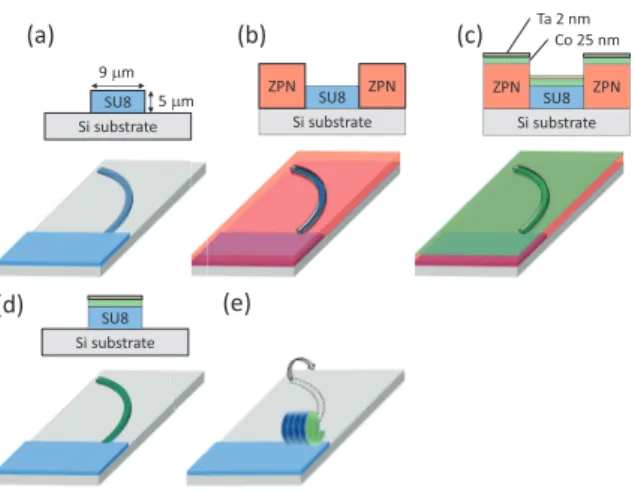
(2) 2. T. Kodama et al.. technique for realizing the microhelix. While preparation of the microhelices using this technique has been reported [8], the magnetic properties, for example, ferromagnetic resonance (FMR), have yet to be studied. An array of the helical structures, fixed on a substrate and aligned in the same direction, is essential for FMR studies because angle-resolved measurement is a key to understanding the origin of the FMR signals. In this paper, we report a fabrication and FMR of an array of micrometer-sized 3D chiral structures of cobalt (Co). An array of the Co microhelices prepared using a technique based on strain-driven self-coiling is fixed on a silicon substrate and aligned in the same direction. We study angle-resolved FMR of the array and find characteristic resonance signals of Co helical structures at low magnetic fields, which do not shift with a change in the dc magnetic field direction. It is important to recognize that the Co helical structures of several tens of µm is much smaller than the wavelength of microwaves in the X-band region (several cm). Artificial structures which are much smaller than the wavelength of electromagnetic waves, are called metamaterials [11]. Microhelices we have realized in this study can thus be referred chiral metamolecules (CMMs) in microwave regions. Such CMMs are particularly of great interest in artificial magnetochiral effects, which is utilized for a one-way mirror [4].. 2 Fabrication Figure 1 shows schematics of the fabrication process and sample cross-sections. The strain-driven self-coiling technique consists of three steps [8]: preparation of an SU8 resist strip [Fig. 1(a)], deposition of metal films [Figs. 1(b)-(d)], and delamination followed by spontaneous coiling of the SU8 strip with metallic layers [Fig. 1(e)]. In the present study, we improved the first and second steps for realizing a microhelix array of Co fixed on a substrate. As shown in Fig. 1(a), the SU8 strip forms an arc-shape, which leads to the control of the coiling direction. The connection of the SU8 strips to large SU8 pads [Fig. 1(a)] and selective deposition of metals only on the strips through the second resist pattern [Figs. 1(b) and 1(c)] followed by a lift-off process [Fig. 1(d)] enables us to fix Co CMMs on a silicon substrate. Detailed fabrication processes are described as follows. An SU8 3005 resist (Nippon Kayaku, Tokyo, Japan) was spin-coated on a silicon substrate at 8000 rpm for 30 sec and pre-baked at 95 ◦ C for 2 min. The thickness of the SU8 layer was 5 µm. The arc-shaped strips 9 µm in width and 1 mm in length with fixed ends were patterned on SU8 using a photolithographic technique (exposure time of 20 sec), followed by post-baking at 65 ◦ C for 1 min and at 95 ◦ C for 3 min. The sample was developed in ethyl lactate for 60 sec and rinsed in isopropanol for 45 sec to obtain the SU8 strips 5 µm in thickness on the substrate [Fig. 1(a)]. The second pattern was formed on the SU8 strips using a ZPN 1150-90 resist (Zeon, Tokyo, Japan) in similar processes [Fig. 1(b)]: the spin-coating of ZPN at 5000 rpm for 30 sec, pre-baking at 105 ◦ C for 1 min, exposure for 5 sec, post-baking at 105 ◦ C for 1 min, development with SD-1 (Tokuyama, Tokyo, Japan) for 60 sec, and rinse with pure water for 30 sec. The second pattern was the negative of the first pattern as depicted in Fig. 1(b) so that the metallic layers can be selectively deposited on the SU8 strips. A Co layer 25 nm in thickness was deposited using a magnetron sputtering method.
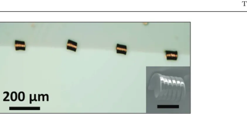
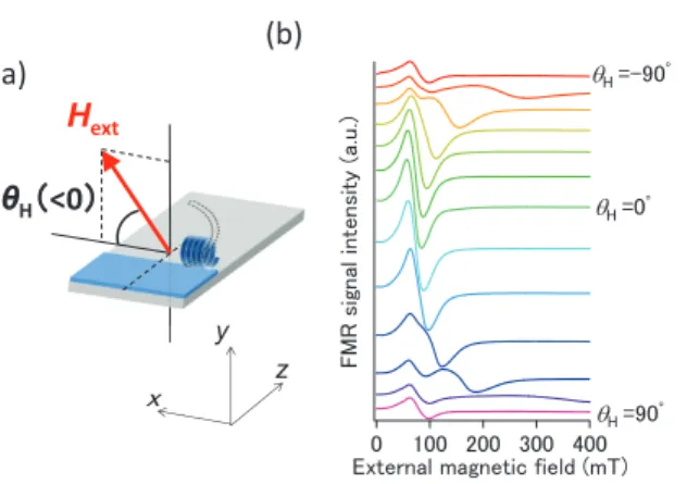
(3) Fabrication and FMR of Co chiral meta-molecule arrays. 3. with an argon gas pressure of 4.2 × 10⁻³ Torr [Fig. 1(c)]. The Co layer was covered by a tantalum (Ta) thin layer 2 nm in thickness in order to avoid the oxidation of Co. The deposition rate of metals was 0.05 nm s−1 . The ZPN layer with metal layers was then lifted-off in ethyl lactate, leaving a 25 nm Co layer covered with a 2 nm Ta layer only on the SU8 strips [Fig. 1(d)]. Finally the sample was dipped into N-methyl-2-pyrrolidone; the SU8 strips with the metal layers were peeled from the substrate and spontaneously coiled due to strains induced by the Co layer [Fig. 1(e)], resulting in the formation of an array of Co CMMs. Figure 2 shows an optical microscopic image of a Co CMM array. We see that the Co CMMs are attached to the silicon substrate and their helical axises are aligned in the same direction. The diameter of the CMM is about 50 µm. The diameter probably depends on both the compressive stress of the thin film and the bending stress of SU8 [8, 12]. The spacing between the CMMs is about 300 µm. The inset shows a scanning electron microscopic (SEM) image of a typical Co CMM. The Co layer on the SU8 strip coils six times. The coiling direction is clockwise, indicating that the arc-shaped strip coils toward the outside of the curvature. By using arc-shaped strips, 70 % of the helix structures coils in the same direction. While Co is utilized for the thin film to induce the strain, other materials are applicable. Smith and co-workers [10] reported that various materials, for example, gold (Au), silicon dioxide (SiO2 ), titanium oxide (TiOx ), and multilayers of copper (Cu) and platinum (Pt) induce the coiling.. 3 Angle-resolved FMR measurements We investigated angle-resolved FMR of the Co CMM array using an X-band (9.8 GHz) electron spin resonance (ESR) spectrometer (JEOL JES-FA100). The measurements were carried out at room temperature. The sample was put into the TE011 cavity. The direction of ac magnetic fields of the X-band microwave in the cavity was parallel to the z axis in Fig. 3(a), i.e., perpendicular to the helical axis of the microhelix. The external dc magnetic field was applied to the sample by an electromagnet. The angle of the dc magnetic field (θH ) was changed in the x-y plane, resulting in the dc magnetic field perpendicular to the ac magnetic field at any values of θH . An increment of θH was 15◦ . The dc field in the direction parallel and perpendicular to the helical axis corresponds to θH = 0◦ and θH = ±90◦ , respectively. Figure 3(b) shows FMR spectra of the Co CMM array corresponding to a photograph in Fig. 2 at various values of θH between -90◦ and 90◦ . This sample is labeled CMM array A. In CMM array A, twelve CMMs are fixed on the silicon substrate. When the angle of the dc magnetic field θH is -90◦ , a resonance signal is observed at 60 mT. We see that the position of this resonance is less dependent on θH . The FMR spectrum of CMM array A shows an additional broad resonance at 182 mT as θH is increased to -75◦ . In striking contrast to the resonance at 60 mT, this broad resonance shifts to a lower magnetic field with increasing θH . At θH = 0◦ , in other words, when the dc magnetic field is parallel to the helical axis, the broad resonance merges with the resonance approximately at 60 mT. The broad resonance shifts to a higher magnetic field as θH further increases up to 75◦ . Figure 4(a) shows FMR spectra of another Co CMM array labeled CMM array B. In this sample seventeen CMMs are fixed on the substrate. The width of the.
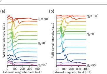
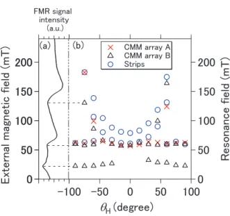
(4) 4. T. Kodama et al.. strips and spacing between the CMMs are identical to those in CMM array A. The strip, however, coils three times. The diameter of the coil is thus slightly larger than that of CMM array A and is about 100 µm. Because the arc-shape of the strips in CMM array B before coiling is reversed, the coiling direction of CMM array B is counter-clockwise, which is opposite to CMM array A. Nevertheless, the CMM array B shows FMR spectra with two-types of resonances, which are similar to those of CMM array A. When θH is -90◦ , resonances are observed at 22 mT and 60 mT, which do not move as θH is increased. Contrastingly, another resonance, which appears at 130 mT when θH is -75◦ , shifts with an increase in θH . Figure 4(b) shows FMR spectra of SU8 strips with Co layer ready to coil and become CMM array B. Thirty-two thin Co strips are fixed on the silicon substrate. In the strips, the resonance peak shifting with an increase in θH is dominant. When θH is varied from -90◦ to -60◦ and from 45◦ to 90◦ , another weak resonance is observed at 60 mT. The weak resonance does not shift as θH is increased. In Fig. 4, the resonance at 60 mT is observed for samples both before and after coiling. However, the intensity ratio of the resonance at 60 mT to the resonance at a higher field becomes large after coiling. Furthermore, the resonance at 22 mT is observed only in the sample after coiling [Fig. 4(a)]. The isotropic resonances at lower fields, whose positions do not depend on the dc field direction with respect to the helical axis, are thus characteristic for the Co CMMs after coiling.. 4 Discussion In Fig. 5 the resonance magnetic fields are plotted as a function of the angle of the applied dc magnetic field. An FMR spectrum of CMM array B at θH = -75◦ in Fig. 4(a) is shown again in Fig. 5(a). As indicated in Fig. 5(a), resonance fields plotted in Fig. 5(b) are evaluated from the top of the resonance peaks in FMR spectra, whereas the true resonance fields are the points where the spectra cross the base line. The red crosses (×) correspond to the resonance field of the CMM array A, which are obtained from the spectra in Fig. 3(b). The resonance fields of CMM array B after coiling are shown by the black triangles (△), which are obtained from the spectra in Fig. 4(a). The blue circles (⃝) correspond to the resonance fields of the Co strips before coiling, which are obtained from the spectra in Fig. 4(b). In all samples, we see resonances, which shift to a lower field as θH increases from -75◦ to 0◦ and shift to a higher field as θH increases from 0◦ to 60◦ . Although not shown here, similar resonance signals were observed in Co thin films without strip patterns. The resonances are thus originated from the FMR of Kittel mode corresponding to a uniform precession of spins in Co films [13]. If the magnetic field is applied in perpendicular to the Co film, the Kittel mode exhibits a resonance at a higher magnetic field owing to the large demagnetization field by the shape anisotropy. When the magnetic field is applied in parallel to the Co film, contrastingly, the Kittel mode shifts to a lower field owing to an assist by the demagnetization field. The shift direction of the Kittel mode due to the shape anisotropy is thus consistent with the shift of the resonances observed in Fig. 5. Additionally we see that the resonance signal due to the Kittel mode in Co strips before coiling (⃝) is accompanied by a weak resonance signal at a higher.
(5) Fabrication and FMR of Co chiral meta-molecule arrays. 5. magnetic field. The weak subsidiary signal was not observed in the Co film without strip patterns. The weak resonance is thus attributed to a localized edge mode of spin waves confined in regions of inhomogeneous magnetic field at the edge of the strip as reported by Jorzick and co-workers [14]. Otherwise, the doublet resonance peaks are caused by the arc-shape of the strip. Figure 5 shows that the isotropic resonances at 60 mT and 22 mT, which do not shift with an increase in θH , are characteristic for the Co CMMs. The isotropic feature at 60 mT is traced back to the Kittel mode of FMR in the Co CMM with shape anisotropy in three dimension. We assume a hollow-bar-like magnetization [8] in the CMM due to the shape anisotropy of the Co film at θH = 0◦ corresponding to the dc magnetic field applied in parallel to all sides of the Co CMM. This brings about the resonance at 60 mT. Contrastingly, when θH = ±90◦ , the dc magnetic field is applied perpendicular to two aspects of the Co CMM, resulting in the resonance at a higher field. However, another two aspects of the 3D CMM is still parallel to the direction of the dc magnetic field. Consequently, the two aspects of the CMM always parallel to the dc magnetic field at any θH causes the resonance at 60 mT, which does not shift with an increase in θH . CMM array B exhibits the resonance at 22 mT, which is much lower than the Kittel mode and does not shift. It is well known that spin waves with nonzero wavenumbers confined in a thin film with a finite thickness shows a number of additional resonance peaks at lower magnetic fields than the Kittel mode [13]. Indeed the resonance at 22 mT is stronger at θH = ±90◦ . Mendach and co-workers [15–17] reported a series of resonance modes which arises from the constructive interference of spin waves traveling along the circumference of the 3D rolled-up ferromagnetic microtubes. Moreover, detailed angle-resolved FMR studies imply presence of residual Co films on the substrate after the lift-off process although not shown here. The spin waves with non-zero wavenumbers in the CMM or in the residuals films on the substrate is thus likely to be an origin of the characteristic resonance at a very low field. 5 Conclusions In conclusions, we have fabricated an array of Co CMMs using the self-coiling of strained bilayer films. By introducing arc-shaped SU8 strips anchored to a large pad and two-step photolithography, we have fixed Co CMMs aligned in the same direction on a substrate. In the angle-resolved FMR studies, the Co CMM array showed resonance peaks at a low magnetic field, which do not shift with an increase in θH . The resonance at 60 mT is traced back to the Kittel mode of the FMR in the microhelix with 3D structures, while the resonance at 22 mT is possibly caused by the spin wave resonance with non-zero wavenumber. Acknowledgements The authors acknowledge S. Koh, S. Uegaki, A. Yoshida for valuable discussions. English proofreading by L. McDowell is also acknowledged. ST acknowledges the partial support of this work by JSPS KAKENHI Grant Number 23654124.. References 1. J. Kishine, I. V. Proskurin, and A. S. Ovchinnikov, Phys. Rev. Lett., 107, 017205 (2011)..
(6) 6. T. Kodama et al.. 2. X. Z. Yu, Y. Onose, N. Kanazawa, J. H. Park, J. H. Han, Y. Matsui, N. Nagaosa, and Y. Tokura, Nature, 465, 901–904, (2010). 3. S. Bord` acs, I. K´ ezsm´ arki, D. Szaller, L. Demk´ o, N. Kida, H. Murakawa, Y. Onose, R. Shimano, T. R˜ o˜ om, U. Nagel, S. Miyahara, N. Furukawa, and Y. Tokura, Nature Physics, 8, 734–738, (2012). 4. S. Tomita, K. Sawada, A. Porokhnyuk, T. Ueda, Phys. Rev. Lett., 113, 235501, (2014). 5. J. P. Park and P. A. Crowell, Phys. Rev. Lett., 95, 167201, (2005). 6. M. Mochizuki and N. Nagaosa, Phys. Rev. Lett., 105, 147202, (2010). 7. V. K. Dugaev, P. Bruno, B. Canals, and C. Lacroix, Phys. Rev. B., 72, 024456, (2005). 8. E. J. Smith, D. Makarov, S. Sanchez, V. M. Fomin, and O. G. Schmidt, Phys. Rev. Lett., 107, 097204, (2011). 9. V. Ya. Prinz, V. A. Selezenev, A. K. Gutakovsky, A. V. Chehovskiy, V. V. Preobrazhenskii, M. A. Putyato, and T. A. Gavrilova, Physica E, 6, 828–831, (2000). 10. E. J. Smith, D. Makarov, and O. G. Schmidt, Soft Matter, 7, 11309–11313, (2011). 11. D. R. Smith, J. B. Pendry, and M. C. K. Wiltshire, Science, 305, 788, (2004). uller, M. S. Khatri, C. Deneke, S. F¨ ahler, Y. F. Mei, E. Berm´ udez Ure˜ na, and O. G. 12. C. M¨ Schmidt, Appl. Phys. Lett., 94, 102510, (2009). 13. C. Kittel, Introduction to Solid State Physics, 7th ed., Wiley, New York, (1995). 14. J. Jorzick, S. O. Demokritov, B. Hillebrands, M. Bailleul, C. Fermon, K. Y. Guslienko, A. N. Slavin, D. V. Berkov, and N. L. Gorn, Phys. Rev. Lett., 88, 047204, (2002). 15. S. Mendach, J. Podbielski, J. Topp, W. Hansen, and D. Heitmann, Appl. Phys. Lett., 93, 262501, (2008). 16. F. Balhorn, S. Mansfeld, A. Krohn, J. Topp, W. Hansen, D. Heitmann, and S. Mendach, Phys. Rev. Lett., 104, 037205 (2010). 17. F. Balhorn, S. Jeni, W. Hansen, D. Heitmann, and S. Mendach, Appl. Phys. Lett., 100 222402, (2012)..
(7) Fabrication and FMR of Co chiral meta-molecule arrays. (a). (b) 9 mm. ZPN SU8 Si substrate. ZPN. 5 mm SU8 Si substrate. (d). SU8 Si substrate. Ta 2 nm Co 25 nm. (c). ZPN SU8 Si substrate. ZPN. (e). Fig. 1 Fabrication procedure of the Co CMM using a strain-driven self-coiling technique.. 7.
(8) 8. T. Kodama et al.. 200 ʅŵ Fig. 2 An optical microscopic image of an array of Co CMMs. Inset: an SEM image of a typical CMM. The scale bar in the inset corresponds to 50 µm..
(9) Fabrication and FMR of Co chiral meta-molecule arrays. 9. (b) (a) Hext θH䠄<0䠅. y. 䡔. z. 䣈䣏䣔䢢䣵䣫䣩䣰䣣䣮䢢䣫䣰䣶䣧䣰䣵䣫䣶䣻䢢䢪䣣䢰䣷䢰䢫. q䣊䢢䢿䢯䢻䢲剱. q䣊䢢䢿䢲剱. q䣊䢢䢿䢻䢲剱 䢲 䢳䢲䢲 䢴䢲䢲 䢵䢲䢲 䢶䢲䢲 䣇䣺䣶䣧䣴䣰䣣䣮䢢䣯䣣䣩䣰䣧䣶䣫䣥䢢䣨䣫䣧䣮䣦䢢䢪䣯䣖䢫. Fig. 3 (a)Schematic illustration of sample configuration in angle-resolved FMR studies. Direction of the external dc magnetic field (Hext ) is defined by the angle (θH ). (b)Angular dependence of FMR spectra observed for an array of Co CMMs (CMM array A) shown in Fig. 2..
(10) 10. T. Kodama et al.. (a). (b) q䣊䢢䢿䢯䢻䢲剱. q䣊䢢䢿䢲剱. q䣊䢢䢿䢻䢲剱 䢲 䢳䢲䢲 䢴䢲䢲 䢵䢲䢲 䢶䢲䢲 䣇䣺䣶䣧䣴䣰䣣䣮䢢䣯䣣䣩䣰䣧䣶䣫䣥䢢䣨䣫䣧䣮䣦䢢䢪䣯䣖䢫. 䣈䣏䣔䢢䣵䣫䣩䣰䣣䣮䢢䣫䣰䣶䣧䣰䣵䣫䣶䣻䢢䢪䣣䢰䣷䢰䢫. 䣈䣏䣔䢢䣵䣫䣩䣰䣣䣮䢢䣫䣰䣶䣧䣰䣵䣫䣶䣻䢢䢪䣣䢰䣷䢰䢫. q䣊䢢䢿䢯䢻䢲剱. q䣊䢢䢿䢲剱. q䣊䢢䢿䢻䢲剱 䢲 䢳䢲䢲 䢴䢲䢲 䢵䢲䢲 䢶䢲䢲 䣇䣺䣶䣧䣴䣰䣣䣮䢢䣯䣣䣩䣰䣧䣶䣫䣥䢢䣨䣫䣧䣮䣦䢢䢪䣯䣖䢫. Fig. 4 Angular dependence of FMR spectra of (a) array of Co CMMs (CMM array B) and (b) Co strips before coiling.. 䣧䣺䣶䣧䣴䣰䣣䣮䢢䣯䣣䣩䣰䣧䣶䣫䣥䢢䣫䣰䣶䣧䣰䣵䣫䣶䣻䢢䢪䣯䣖䢫.
(11) Fabrication and FMR of Co chiral meta-molecule arrays. 11. 䢪䣣䢫. 䢪䣤䢫. 䢢䢢䣅䣏䣏䢢䣣䣴䣴䣣䣻䢢䣃 䢢䢢䣅䣏䣏䢢䣣䣴䣴䣣䣻䢢䣄 䢢䢢䣕䣶䣴䣫䣲䣵. 䢴䢲䢲. 䢴䢲䢲. 䢳䢷䢲. 䢳䢷䢲. 䢳䢲䢲. 䢳䢲䢲. 䢷䢲. 䢷䢲. 䢲 䢯䢳䢲䢲 䢯䢷䢲. 䢲 䢷䢲 q䣊䢢䢪䣦䣧䣩䣴䣧䣧䢫. 䣔䣧䣵䣱䣰䣣䣰䣥䣧䢢䣨䣫䣧䣮䣦䢢䢪䣯䣖䢫. 䣇䣺䣶䣧䣴䣰䣣䣮䢢䣯䣣䣩䣰䣧䣶䣫䣥䢢䣨䣫䣧䣮䣦䢢䢪䣯䣖䢫. 䣈䣏䣔䢢䣵䣫䣩䣰䣣䣮 䢢䣫䣰䣶䣧䣰䣵䣫䣶䣻 䢢䢢䢪䣣䢰䣷䢰䢫. 䢲 䢳䢲䢲. Fig. 5 (a) A spectrum of CMM array B at θH = -75◦ . (b) The resonance magnetic fields are plotted as a function of θH . Red crosses correspond to Co CMM array A. Black triangles correspond to Co CMM array B. Blue circles correspond to the Co strips before coiling to CMM array B..
(12)
図
+2
関連したドキュメント
熱力学計算によれば、この地下水中において安定なのは FeSe 2 (cr)で、Se 濃度はこの固相の 溶解度である 10 -9 ~10 -8 mol dm
Standard domino tableaux have already been considered by many authors [33], [6], [34], [8], [1], but, to the best of our knowledge, the expression of the
Rev. Localization in bundles of uniform spaces. Colom- biana Mat. Representation of rings by sections. Representation of algebras by continuous sections.. Categories for the
H ernández , Positive and free boundary solutions to singular nonlinear elliptic problems with absorption; An overview and open problems, in: Proceedings of the Variational
7 The current density J z at the center of the channel is higher for a micropolar fluid than that for a Newtonian fluid, and it will decrease as the microrotation parameter
Keywords: Convex order ; Fréchet distribution ; Median ; Mittag-Leffler distribution ; Mittag- Leffler function ; Stable distribution ; Stochastic order.. AMS MSC 2010: Primary 60E05
We prove the coincidence of the two definitions of the integrated density of states (IDS) for Schr¨ odinger operators with strongly singular magnetic fields and scalar potentials:
В данной работе приводится алгоритм решения обратной динамической задачи сейсмики в частотной области для горизонтально-слоистой среды
