JAIST Repository
https://dspace.jaist.ac.jp/
Title
Field Test Results for Beam and Null Simultaneous
Steering S/T-Equalizer in Broadband Mobile
Communication Environment
Author(s)
Miki, N.; Asai, T.; Tomisato, S.; Matsumoto, T.
Citation
IEEE VTS-Fall VTC 2000. 52nd Vehicular Technology
Conference, 2000., 4: 1663-1668
Issue Date
2000-09
Type
Conference Paper
Text version
publisher
URL
http://hdl.handle.net/10119/4823
Rights
Copyright (c)2000 IEEE. Reprinted from IEEE
VTS-Fall VTC 2000. 52nd Vehicular Technology
Conference, 2000. This material is posted here
with permission of the IEEE. Such permission of
the IEEE does not in any way imply IEEE
endorsement of any of JAIST's products or
services. Internal or personal use of this
material is permitted. However, permission to
reprint/republish this material for advertising
or promotional purposes or for creating new
collective works for resale or redistribution
must be obtained from the IEEE by writing to
pubs-permissions@ieee.org. By choosing to view
this document, you agree to all provisions of the
copyright laws protecting it.
Field Test Results for Beam and Null Simultaneous Steering S/T-Equalizer
in Broadband Mobile Communication Environment
Nobuhiko Miki, Takahiro
Asai, Shigeru Tomisato, and Tadashi Matsumoto
Wireless Laboratories,
NTT DoCoMo Inc.,
3-5 Hikari-no-oh,
Y
okosuka-shi, Kanagawa-ken 239-8536, Japan
[
nmiki, asai,tomisato, matumoto] @mlab.yrp.nttdocomo.co.jp
Abstract
This paper proposes a beam and null simultaneous steering Space-Time Equalizer (9T-Equalizer). The proposed S/T-Equalizer performs separated S/T-signal processing in order to reduce computational complexity to a practical level. For spatial signal processing, a new Adaptive Array Antenna algorithm is used that combines the beam and null steering concepts. For temporal signal processing, a conventional delayed decision feedback sequence estimation equalizer may be used. The proposed Sfl-Equalizer was prototyped. A series offield tests was then conducted using the SGHzfrequency band to evaluate transmission performance of the proposed system. The results show that the proposed S/T-Equalizer can reduce inter-symbol interference effects while maintaining reasonable signal strength, thereby improving BER performance.
1.
Introduction
Mobile multimedia communications demand the creation of broadband signal transmission techniques that
offer transmission rates of tens of Mbps. These techniques must overcome problems such as CO-Channel Interference (CCI) and Inter-Symbol Interference
(ISI),
aswell as the relatively large propagation loss inherent to broadband mobile communications. Joint Space-Time- Equalization (S/T-Equalization) is considered most effective in reaching these goals [ 11, [2].
SR-Equalization i s a unified concept combining conventional adaptive array antennas (AAAs) and temporal equalizers. Temporal equalizers aim to reduce
IS1 and combine delayed desired signal components, while A A A s suppress CCI and enhance antenna gain towards the desired signal’s incident angle. Optimal performance can be achieved through two-dimensional (joint spatial and temporal) optimization of the SE- Equalizer’s parameters [3]. Unfortunately, it is prohibitively complex in many cases to implement the
optimal S/T-Equalizer, and a technique that significantly reduces the complexity is required.
This paper proposes a new S/T-Equalization technique that separates spatial and temporal signal processing. This separation reduces the computational complexity of signal processing to a practical level. To avoid conflict between the spatial and temporal equalizers, timing control of equalizer operation is needed. A new AAA algorithm is proposed for spatial equalization. The proposed algorithm combines the beam and null steering concepts; a sharp beam is steered towards the desired signal while nulls are steered towards interferers. The AAA is followed by a
temporal equalizer. Although any form of equalizer can be used for temporal equalization, the Delayed Decision Feedback Sequence Estimation (DDFSE) equalizer may be a good choice [4] since it offers a reasonable tradeoff between performance and complexity.
A
series of field tests was then conducted in the 5GHz frequency band to evaluate signal transmission performance of the prototyped system. This paper is organized as follows. Section 2 describes the configuration of the proposed SR-Equalizer. Section 3 describes details of the prototyping, along with results of the field tests. Section 4 concludes this paper.
The proposed SR-Equalizer was prototyped.
2.
Configuration
of S/T-Equalizer
Figure 1 shows a block diagram of the proposed SIT- Equalizer. Parameter Estimator-1 (PE-1) performs spatial signal processing for the proposed beam and null steering
AAA algorithm, and Parameter Estimator-2 (PE-2) performs temporal signal processing for temporal equalization, both take run independently of the other.
2.1.
Spatial Equalization
The proposed AAA algorithm first estimates the direction-of-arrival (DOAS) of incident signals. It then
forms a beam pattern based on the DOA estimates: a
m
Parameter
n
Estimator-;!Figure 1. Configuration of proposed S/T-Equalizer
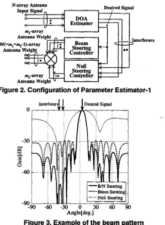
sharp beam is steered towards the desired signal and nulls towards other signals. Figure 2 shows a detailed configuration of PE-1. The DOA estimator in Figd uses a super-resolution algorithm to estimate DOAs and powers of signals impinging on an N-element array antenna. The MUSIC algorithm [5] may be used for DOA estimation. The simple classification used here is that the strongest of the detected signals is the desired signal, and the others are the interferers. This classification is reasonable in relatively simple propagation environments. In the presence of both multi- path and interference components, the strongest signal detected may not be the signal that should be detected but indeed may be the one that should be suppressed. In such complex environments, the true desired could be determined with the help of a higher layer of the system control.
Let DOA of the desired signal be denoted by
6,
and DOAs of interferers byQ
( 1 9 s - 1 ) , where L is the number of signals detected by the DOA estimator. LetG’ denote the detected desired signal power, and a;’ (IlilL-1) the powers of the others. The M-element array antenna’s weight vector can be calculated by using
4
(OlilL-1) and q2 ( 0 3 s - 1 ) so that it forms a beam steered towards the desired signal while forming nulls
towards the interferers.
Let c =
(c,~c~~---,c,,,)~
denote the mlelement array antenna’s weight distribution that forms a specific beam pattern. The Taylor or Chebyshev distributions may be used as e. It follows that the ml-element array antenna’s weight vector for beam steering, wbem, can be calculated by using6
of the desired signal’s DOA aswkm = (clsb,l (eO),cZsb,2(eO),~’~7cmIsb,~l
where sb(eO) = ( s b , l < e O ) 7 s b , ~ < e O ) 7 . - ’ 7 s , ,
> ( l ) is the
steering vector for
6.
An mz-element array antenna’s weight vector for null steering, WmD, can be calculated by using the DOAs of the desired signal and the interferers. If the number of interferers (15-1) is larger than the null steering array antenna’s degree-of-freedom m2-l, not
all
the interferersDesired Signal N-array Antenna Input Signal
,,
0 > 0 , I I . DOA 0 I J : v’
fitmator-
m.-arrav-
I I 1 I M( =m,+%-l)-array Antenna Weight ControllerFigure 2. Configuration of Parameter Estimator-1
---Beam Steering
U
-Null Steering3 0 6 0 9 0 Anglerdeg.1
Figure 3. Example of the beam pattern
can be canceled. In such cases, the mz-1 strongest interferers are selected and canceled. In order to calculate the array antenna’s weight vector that has nulls towards m2-1 interferers, the Howell-Applebaum algorirhm [6] can be used. The array correlation matrix
R
is defined as;-1
R
=k+,,(ei)snH(ei)
+ 0 2 1 ,,
(2) i=lwhere s,,(@, U?, and
2
represent the m2-elemnt steeringvectors associated with the
directions
6
(11i5m2-1), powers of interferers and noise, mpectively. 1, denotes anmpm2 unit matrix.
The null steering array antenna’s weight vector
W,,
can then be expressed as
where s,,(&) represents the mz-element steering vector associated with the direction
6.
AnM
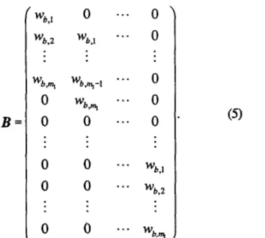
(=ml+mz-l)- element array antenna’s weight vector for beam and null steering can finally be obtained from Wkm and W,, aswhere
*
denotes a convolution between the two matrixes.Eq.(4) can be folded into W=B Wnua where matrix B is given by
WAU = R-’sn(6)7 (3)
B =
wb,l wb,2 wbrt, 0 0 00
0 0 wb,l wb,m,-l W b n 0 0 0 0...
0 0...
0 0 0...
...
...
wb,l * ’ wb,2...
wb.-...
Figure 3 shows a typical beam pattern obtained as a result of the proposed algorithm, where three signals are assumed to have been impinging on the antenna. The thick,
thin,
and dashed lines represent the beam patterns corresponding to W,Wkm,
and W,, respectively. The beam pattern withw
inherits both wbe- and W,,,,”’sdesigned beam patterns: the sharp main beam is steered towards the desired signal’s DOA
I%
and the nulls towards the interferers.2.2. Temporal Equalization
Even though the spatial equalizer with the proposed beam and null steering algorithm can eliminate the effects of interference and most of the delayed desired signal components, some of the delayed desired signal components, having incident angles very close to the desired signal, may also be captured by the main beam. These components cause IS1 distortion on the received desired signal at the output of the spatial equalizer. The primary purpose of the temporal equalizer following the spatial equalizer is to eliminate the IS1 caused by the delayed desired signal components captured by the main beam.
For temporal equalization, Maximum Likelihood Sequence Estimation (MLSE) equalizers [7] are known to achieve optimal performance. Unfortunately, the computational complexity of MLSE equalizers is exponential to the delay spread on the received desired signal, and hence it is impractical to use MLSE in ISI-rich broadband mobile communication environments. Therefore, some type of complexity-reduced sub-optimal detector is needed for temporal equalization.
23. Timing Control
If the taps of the spatial and temporal equalizers are changed asynchronously, updating the spatial e q d z e r
taps may interfere with the signal reception using the temporal equalizer. Hence, spatial and temporal signal processing should be separated such that the equalizers can update their taps independently. An advantage of the DOA-based spatial equalizer is that DOAs of the incident signals basically stay constant over several milliseconds, which corresponds to a couple of data frames. Hence the spatial equalizer taps can be kept constant over a couple of frames, while those of the temporal equalizer have to be updated frame-by-frame.
This
allows, without causing severe performance degradation, the taps of the spatial equalizer to be updated in the gap between frames. The proposed separated SR-Equalizer utilizes this concept, and so demands timing control of operation.3.
Field Test Results
3.1. Specifications of Prototyped System
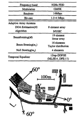
A prototype of the proposed S/r-Equalizer was built for 1.5Mbpsx4channels GMSK signal transmission. Because of the overhead for some implementation purposes, the signal transmission baudrate was 14Mbps. A series of field tests was conducted using the prototyped system. Table 1 summarizes major specifications of the prototyped system. For DOA estimation, an 8element linear array was used. The MUSIC algorithm was run on the prototyped system using the %element linear array output vector to detect DOAs. A 19-element linear array, which was located separately from but close enough in
space to the DOA detection’s 8element array, was used for beam-forming. Of the 19 antenna elements, 16 were used for beam steering and 4 for null steering, which satisfies ml+ml-l=M. Taylor distribution was used as the m a y antenna’s weight distribution for beam steering.
For temporal equalization, a DDFSE equalizer [4] was
used. The DDFSE equalizer combines the concepts of the MLSE equalizer and the Decision Feedback Equalizer
@FE);
by eliminating some of the MLSE states from the trellis diagram for the channel, its complexity remains feasible. The DDFSE equalizer has two sets of taps: one for MLSE, the other for D E . In the prototyped system, MLSE has 4 taps and DFE 11 taps, resulting in 15 taps intotal, which, with the symbol duration T, covers delay spread of up to 14T. In addition to signal detection, the temporal equalizer also outputs an estimate of the delay profile as .a result of channel estimation.
3.2. Field Test Courses
A series of field tests was conducted to evaluate uplink (mobile-to-base) signal transmission p e r f o m c e of the prototyped system. Figure 4 shows the measurement
course for the field tests. As a Base Station (BS), the prototyped proposed S/T-Equalizer was located on the top of Building X to receive the signal transmitted from a Mobile Station (MS). BS antenna height was about 2Om.
An omnidirectional monopole antenna was located on the top of the vehicle, and used for, signal transmission. Points A and b and their vicinities have Line-Of-Sight (LOS) paths: other locations are non LOS (NLOS) regions due to the presence of Buildings X and
Y.
Table 1. Specification of prototyped system ~ ~ ~~ -~
Frequency band 5GHz FDD
Modulation GMSK
Baudrate 14Mbps
Bit-rate 1 5 x 4 Mbps Adaptive Array Antenna
DOA Estimation(N) 8 ele" array
Algorithm MUSIC
19 element 16 elements B e a " i n g ( M , linear array
Beam Taylor distriiution
Null Steering(%) 4 elements
15tap-DDFSE (MLSE4, DFE:I 1)
Temporal Equalizer
Figure 4. Measurement course for field tests
33.
BER
Performance under
LOS
Conditions
BER performance was first evaluated with the MS
located at Point A. The DOA estimator detected only a single path having 10 degree DOA, which corresponds to the look angle from the BS to Point A. Figure 5 shows measured BERs versus received EJNo at the array output. In order to change the EJNo value, the transmission power was controlled. The solid and dashed lines represent the theoretical and simulated BER curves. Delay spread estimated by the temporal equalizer at Point A was less than lT, and hence no BER floor is observed. The measured BER is 2dB worse than the simulation result.
This is reasonable considering the impairments inherent in hardware implementation.
IO0 I . . . , , , . , . . . , . 1 , . I
E /N,(dB)
5
Figure 5. BER perfbrmances at Point A
3.4.
BER Performance under NLOS Conditions
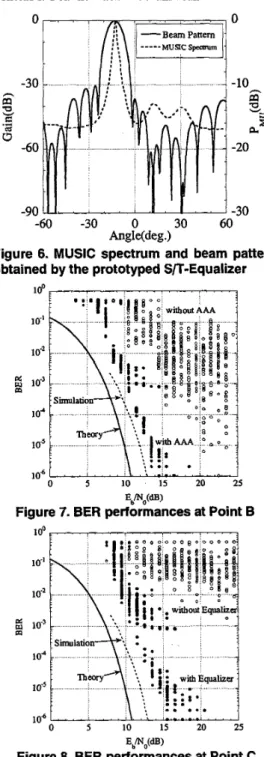
BER performance was then evaluated when the MS was located at Points B and C, where there were no LOS paths kom the BS. Figure 6 shows a MUSIC spectnun and its corresponding beam pattern obtained by the prototyped system when the MS was located at Point B.
In this case, three signals having DOAs of -13 degrees, 10 degrees, and 23 degrees were detected. The strongest signal of the three was the one with -13 degree DOA. Hence, the beam was steered towards that direction and the nulls were formed towards the directions of the other signals.
Figure 7 shows measured BERs at Point B. The symbols and 0 plot BER performance with and
without AAA, respectively. In both cases, the DDFSE temporal equalizer was used. The delay spread evaluated by the temporal equalizer without AAA was about 3ST, which exceeds MLSE capacity of the DDFSE equalizer.
This
is a major cause of degradation in the BER performance withoutAAA.
With AAA, the delay spread can be reduced to less than IT because AAA can suppress delayed signal components. This improves the BER performance.Due to the blockage from Building
Y,
Point C is also anNLOS
region. Figure 8 shows measured BERs when the MS was located at Point C. The symbols and0 plot BER performance with and without the temporal
equalizer, respectively. In both cases, A L 4 was used. The delay spread estimated by the temporal equalizer was about 2.5T. This indicates the existence of delayed components falling on the A A A ' s main beam, so the BER
is degraded without the DDFSE temporal equalizer. The conclusion is that spatial equalization by itself can not achieve acceptable BERs if delayed desired signal components fall on the antenna's main beam.
Beam Panem Musc sp=" -10-
s
is
!s
3 E E .d a -20d
-30 _ . -60 -30 0 30 60 Angle(deg.)Figure 6. MUSIC spectrum and beam pattern obtained by the prototyped S/T-Equalizer
;... .
0 5 10 15 20 25
IOb
1
' ' ' . ' ' ' ' '11.
' . - I - . - . ' 'J
E,Mo(dB)
Figure 7. BER performances at Point B
1 0 0 , . . . . , . . . , , . , . . ,a .. . ' 1
0 5 10 15 20 25
Ed"(dB)
Figure 8. BER performances at Point C
0-7803-6507-0/00i$10.00 02000 IEEE 1667
3.5.
BER
Performance under Dynamic
Condition
BER performance was evaluated when the MS moved
from Point A to Point C as shown in Fig.4. Figure 9
shows measured BER performance for average vehicle speed of 30km/h. The thick, thin, and dashed lines represent the measured BERs with the proposed SIT- Equalizer, with just the spatial equalizer, and with just the temporal equalizer, respectively. The MS started from Point A; it passed through Point C 15 seconds later, and reached Point C 50 seconds later. At Point B, the BER was smaller than lo4 due to the LOS path. At most of the locations over the entire 40Om measured course, the proposed S/T-Equalizer can achieve BERs better than
lo4. With just the spatid equalizer or just the temporal equalizer, the BERs exceeded 10" over more than 50% of the entire course. This suggests that the joint use of spatial and temporal equalizers can significantly improve BER performance.
-with AAA I with Equalizer with AAA I without Equalizer
without AAA I with E q u a l i
lodO 10 20 30 40
:
TimeW
0 Figure 9. BER performances at the average speed of
30km/h
4.
Conclusion
In this paper, we have proposed a new S/T-Equalizer featuring separated spatial and temporal signal processing. This separation reduces computational complexity to a
practical level. A simultaneous beam and null steering AAA algorithm was derived for the S/T-Equalizer. The simultaneous beam and null steering
AAA
algorithm combines the concepts of beam steering and null steering: a sharp beam is steered towards the desired signal and nulls towards other signals. The proposed S/T-Equalizer was prototyped, and field tests were conducted to evaluate uplink transmission performance of the proposed system. BER performance under NLOS and dynamic conditions suggests that the joint use of spatial and temporalequalizers can significantly improve
BER
performances over the case where either spatial equalizer or temporal equalizer is used alone.Acknowledgements
The authors would like to thank Dr. Nobuo Nakajima, former senior vice president of
NTT
DoCoMo Inc., forhis encouragement during this research.
References
[I] W. Modestio and V. Eyboglu, "Integrated multielement receiver structures for spatially distributed interference channels," IEEE Trans. IT, vol. IT-32, N0.2, pp.195-219,
Mar. 1986.
[2] R. Kohno, "Spatial and Temporal Communication Theory Using Adaptive Antenna Array," IEEE Personal Communications, pp.28-35, Feb. 1998.
[3] K. Fukawa and T. Matsumoto, "A New Joint Array SignaI Processing Structure and Maximum Likelihood Sequence Estimation in Mobile Radio Communications," Smart
Anfenna Workshop '97,1997.
[4] A. Duel-Hallen and C. Heegard, "Delayed Decision- Feedback Sequence Estimation," IEEE Trans. Commun.,
vo1.37, No.5, pp.428436, May 1989.
[5] R. Schmidt, "Multiple Emitter Location and Si@ Parameter
Estimation," IEEE Tram.., Vo1.M-34, No.3, pp276-280,1986.
(61 S. Applebaum, "Adaptive Arrays," IEEE Trans. AP, AP-24,
[7] K. Fukawa and H. Suzuki, "Adaptive equalization with RLS-
MLSE for frequency selective fast fading mobile radio
channels," IEEE GCOM '91, Phoenix, pp.16.6.1-16.6.5, Dec. 1991.