第 54 卷 第 5 期
2019 年 10 月
JOURNAL OF SOUTHWEST JIAOTONG UNIVERSITY
Vol.54 No.5
Oct. 2019
ISSN: 0258-2724 DOI:10.35741/issn.0258-2724.54.5.37
M
ULTI
-F
OCUS
I
MAGE
F
USION
B
ASED ON
S
TATIONARY
W
AVELET
T
RANSFORM AND
PCA
ON
YCBCR
C
OLOR
S
PACE
Alaa A. Abdullatifa, Firas A. Abdullatifa , Amna al Safara
aCollege of Education for pure science / Ibn Al-Haitham, University of Baghdad, Iraq
alaa.a.h@ihcoedu.uobaghdad.edu.iq, Firas.alobaedy@ihcoedu.uobaghdad.edu.iq, amnaalsafar1@yahoo.com
Abstract
The multi-focus image fusion method can fuse more than one focused image to generate a single image with more accurate description. The purpose of image fusion is to generate one image by combining information from many source images of the same scene. In this paper, a multi-focus image fusion method is proposed with a hybrid pixel level obtained in the spatial and transform domains. The proposed method is implemented on multi-focus source images in YCbCr color space. As the first step two-level stationary wavelet transform was applied on the Y channel of two source images. The fused Y channel is implemented by using many fusion rule techniques. The Cb and Cr channels of the source images are fused using principal component analysis (PCA). The proposed method performance is evaluated in terms of PSNR, RMSE and SSIM. The results show that the fusion quality of the proposed algorithm is better than obtained by several other fusion methods, including SWT, PCA with RGB source images and PCA with YCbCr source images.
Keywords: Multi-focus image fusion, YcbCr color space, stationary wavelet transform, principal component analysis (PCA)
摘要 : 多焦点图像融合方法可以融合一个以上的聚焦图像,以生成具有更准确描述的单个图像。图像融合
的目的是通过组合来自同一场景的许多源图像的信息来生成一个图像。本文提出了一种在空间域和变换域 中获得混合像素水平的多焦点图像融合方法。该方法在 YCbCr 色彩空间中的多焦点源图像上实现。作为第 一步,在两个源图像的 Y 通道上应用了两级平稳小波变换。通过使用许多融合规则技术来实现融合的 Y 通 道。使用主成分分析(PCA)融合源图像的 Cb 和 Cr 通道。建议的方法性能根据 PSNR,RMSE 和 SSIM 进 行评估。结果表明,与 SWT,具有 RGB 源图像的 PCA 和具有 YCbCr 源图像的 PCA 相比,该算法的融合 质量要好于其他几种融合方法。
关键词: 多焦点图像融合,YcbCr 颜色空间,平稳小波变换,主成分分析(PCA)
I. I
NTRODUCTIONThe sensor of imaging technology is affected by many factors of the imaging environment, for that the generated image may be displayed with noise and superficiality. Image fusion is defined as the process of producing a more accurate image by the fusion of multiple same scene
images [1]. Multi-focus image fusion creates one image from two or more images that have same scenes, with these images having different focus points. The resultant image after the fused method has been applied has more information than the source images and is called the all-in-focus image [2]. Multi-all-in-focus image fusion has been used in different areas, such as remote
sensing, medical imaging, transportation, military applications and machine vision [3].
Pixel-level fusion uses the pixels of an image, being the lowest level of fusion when compared to others like feature level fusion and decision level fusion. Regarding the latter two, the fused image contains more information and is more conducive to computer processing and the human eye. There are two categories of pixel level fusion: image fusion methods based on the spatial and transform domains [4], [5].
The method in the spatial domain depends on selecting the pixels from the sources images to form the fused image. There are many methods used to determine the clear area of selecting pixels in the resource images like certain sharpness indicator, by window or by image segmentation of a specific size [6].
Several methods have been devised to perform image fusion with the transformation method, including wavelet transform, discrete wavelet transform (DWT), shift invariant wavelet transform (SIDWT), DCT based on average or DCT based on spatial frequency and non-subsampled contourlet transform (NSCT) [6], [7]. In the transformation domain image fusion methods are based on converting the original image into transformation coefficients. Then, these are fused by the appropriate fusion rules and finally, there is reconstruction of the fusion coefficients to obtain the fusion image [8].
In this paper, pixel level fusion is applied to special and transform domains. The source images, firstly, are converted into YCbCr color space and then two levels of SWT are applied to Y channel. Different fusion rules are used to fuse the SWT coefficient, while the PCA technique is used to fuse the Cb and Cr channels.
The rest of the paper is arranged as follows: The aim of the research is explained in section II. The basic theory is expounded in Section III. Section IV describes in detail the proposed image fusion algorithm. Parametric evaluation and the experimental results are discussed in Section V. Finally, Section VI presents the conclusions.
II.
THE AIM OF THE RESEARCHThis research is aimed at proposing a method to enhance the scene of two different focus images by using two different appropriate rules to fuse approximation and detail sub-band of SWT for Y channels of the source images, while the PCA is used for fused Cb and Cr. For that, the research focuses on fused pixels in transform and spatial domains. This leads to better results according to many evaluation measurements
because it uses the advantages of the two domains.
III. B
ASIC THEORYThe proposed method is based on the concept of many theories as follows:
A. YCbCr Color Space
The YCbCr color space can be considered as a scaled and offset version of YUV color space. The luminance component is represented by Y, while Cb and Cr are chromatic ones. The Cb component is the difference between the blue part of the RGB and the reference value, while Cr reflects the difference between the red part of RGB and the reference value. The advantage of YCbCr color space is that it can be used to separate the three channels and operate on each one separately without any effect. The equations that are used to convert RGB color space to YCbCr color space are as follows [10]:
( 𝑦 𝐶𝑏 𝐶𝑟 ) = [ 0.257 0.564 0.098 −0.148 −0.291 0.439 0.439 −0.368 −0.071 ] ( 𝑅 𝐺 𝐵 ) + [ 16 128 128 ] (1) ( 𝑅 𝐺 𝐵 ) = [ 1.164 0 1.596 1.164 −0.392 −0.813 1.164 2.017 0 ] ( 𝑌 − 16 𝐶𝑏 − 128 𝐶𝑟 − 128 ) (2) where, Y has a range of [16-235], whilst Cb and Cr have ranges of [16-240].
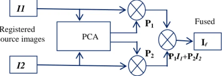
B. Principal component analysis (PCA) One of the pixel level fusion techniques, PCA, is widely used in image processing, machine learning, image fusion and many other applications. With PCA, the number of correlated variables are transformed into uncorrelated variables, which reduces the multidimensional data sets into lower dimensions for analysis. The technique calculates the weights for each source image according to an eigenvector. The eigenvector is produced by the largest eigenvalue of the covariance matrix of each source image. By choosing the highest eigenvalue vector to be the principle component the number of dimensions is reduced, thus leading to faster computation. Figure (1) shows the flow diagram for the PCA technique [11].
Figure 1. Flow diagram for the PCA technique I1 I2 If PCA P1I1+P2I2 Registered source images P1 P2 Fused image
The steps of PCA analysis are as follows [12]:
- calculate the column vector based on the source image;
- create covariance 𝐶𝑣𝑎𝑟 and correlation
matrix A based on the data set of the input images x1 and x2, as in equations 3 and 4.
𝐴 = [ 𝑣1 𝑐𝑣𝑎𝑟(1,2)
𝑐𝑣𝑎𝑟(1,2) 𝑣2 ] (3)
𝐶𝑣𝑎𝑟=
(∑(𝑥1−𝑥̅1)×(𝑥2−𝑥̅2))
𝑁−1 (4)
where v1, and v2, denote the variance, Cvar
(1,2) represents the covariance and N is the number of terms.
The eigenvalues can be calculated by solving:
𝐷𝑒𝑡|𝐴 − 𝜆𝐼| = 0 (5)
where λ is the eigenvalue.
[ 𝑣1 𝑐𝑣𝑎𝑟(1,2)
𝑐𝑣𝑎𝑟(1,2) 𝑣2 ] − 𝜆𝐼= 0 (6)
((v1- 𝜆)×(v2-𝜆)) × Cvar(1, 2) 2
=0 (7)
The eigenvectors are calculated as follows: ⌈𝐴 − 𝜆𝐼⌉ × [𝑋] = 0 (8)
The co-ordinates for each point in the direction of the principal component are given by:
Pcj= ai1 y1 + ai2 y2 ………. ain yn (9)
where, a1 is the coefficient of factor i , pcj is
the jth principle component and y1, y2, ….. yn
represent the coordinates of each data point. C. Stationary Wavelet Transform
A discrete wavelet transform is time-variant and to reduce the poor directionality and translation variation, an undecimated approach has to be used, called a stationary wavelet transform (SWT). This has the properties of shift invariance and redundancy such that it is more efficient when compared to the traditional wavelet transform used for multi-scale transform methods and it is a non-redundant decomposition algorithm. The sub-image size in SWT does not decrease because it applies up-sampling filter instead of the down-up-sampling operation for that the most information of source
images can be kept in the decomposed sub-images. SWT uses multi scale decomposition that can extract the small features in fine scales and the large ones in coarse scales. The presentation of images at each scale with SWT retains the native number of pixels throughout and it does not down sample the coefficients, which is why SWT was selected over DWT [13], [14]. The decomposition of the image in the SWT domain involves an approximation sub-band (LL) and detail sub-sub-bands (LH, HL and HH), as shown in Figure 2 [15].
Figure 2. The decomposition of the image in the SWT domain
IV.
T
HEP
ROPOSEDM
ETHODWith the proposed method the source images are converted to YCbCr color spaces and then, a two-level SWT is applied to the Y channel of each image. Different fusion rules are used to fuse the SWT sub-band decomposition to get better results. The average rule is used to fuse the approximation sub-band (LL), while the detail sub-bands (LH, HL, and HH) are fused under another rule, PCA is used to fuse the Cb and Cr channels. Figure (3) shows the block diagram of the proposed method.
The steps of the proposed algorithm with fusion rules equations are shown in algorithm (1)
Algorithm (1): the proposed fusion
Input: two source multi focus images (A and B) Output: fused image
Start
Step 1: transform source images from RGB to YCbCr color space.
Step 2: apply two-level stationary wavelet transform to the Y channel of A and B.
Step 3: fuse the approximation sub-band LL by the average rule as follows:
FLL= (ALL+BLL)/2 (11)
Fuse the detail sub-bands LH, HL and HH as follows:
WLH=absolute (ALH)-absolute (BLH) (12) FLH= (WLH) (ALH) + not (WLH) (BLH) (13)
WHL=absolute (AHL)-absolute (BHL) (14)
FLH= (WHL) (AHL) + not (WHL) (BHL) (15)
WHH=absolute (AHH)-absolute (BHH) (16)
FHH= (WHH)(AHH) + not (WHH)(BHH) (17)
Step 4: apply inverse SWT to FLL, FLH, FHL and FHH to get FY . Step 5: fuse the Cb channels of images A and B by PCA to get FCb. Step 6: fuse the Cr channels of images A and B by PCA to get FCr. Step7: convert FY, FCb, and FCr into RGB color space to get the fused image. End. Figure 3. Block diagram of the proposed method
V.
R
ESULTS ANDD
ISCUSSION A. Parametric evaluation There are several quantitative assessment metrics used to compare various fusion algorithms depending on the reference image. One of them is Root Mean Squared Error (RMSE), which is usually found between the fused image and the original. The smaller the value, then the better the fusion method [16]. 𝑅𝑀𝑆𝐸√𝑀×𝑁1 ∑ ∑𝑁 (𝑅(𝑖, 𝑗) − 𝐹(𝑖, 𝑗))2 𝑗=1 𝑀 𝑖=1 (18) Peak Signal to Noise Ratio (PSNR) is another parametric deployed for fused image quality assessment, which is calculated as: 𝑃𝑆𝑁𝑅 = 10𝑙𝑜𝑔10 (𝑀×𝑁)2 ∑ ∑𝑁 [𝑅(𝑖,𝑗)−𝐹(𝑖,𝑗)]2 𝑗=1 𝑀 𝑖=1 (19)SSIM is used to calculate the structure similarity between the fused image and the reference one. A better fusion result is indicated by a higher value of PSNR and SSIM [17]. The latter is defined as: 𝑆𝑆𝐼𝑀(𝑅, 𝐹) = ( 2𝜇𝑟𝜇𝑓+𝑐1 𝜇2 𝑟+𝜇2𝑓+𝑐1) 𝛼. ( 2𝜎𝑟𝜎𝑓+𝑐2 𝜎2 𝑟+𝜎2𝑓+𝑐2) 𝛽. (𝜎𝑟𝑓+𝑐3 𝜎𝑟𝜎𝑓+𝑐3) 𝛾 (20)
where, R(i, j) are the pixel values of the reference image, and F(i, j) are those of the fused one. The image size is M x N, whilst 𝜇𝑟, 𝜇𝑓, 𝜎2𝑟, 𝜎2𝑓, 𝜎𝑟𝑓 are the mean, variance, and
covariance, respectively. 𝑐1, 𝑐2, 𝑐3 are constants
closing to zero.
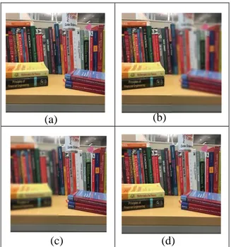
B. The results of the proposed method The proposed method has been implemented on multi focus color images in YCbCr color space. The pixel level image fusion technique is implemented in the spectral and transform domains. Firstly, two levels of SWT were applied on the Y channel of two source images, this being undertaken after many experiments with different levels. A different fuse rule was used to fuse the coefficients of the four sub-bands to reach for appropriate fused rule, while the Cb and Cr channels were fused using PCA. The proposed algorithm was applied on many images of size 256 x 256 , including cars, books and a tree. The reference, source images with right and left focus and the fused images after applying the proposed algorithm are presented in figure (4), figure (5) and figure (6).
(a) (b) (c) (d) Fusion with different rules Source image B Source image A Convert RGB to YCbCr Convert RGB to YCbCr Two level SWT Two level SWT PCA PCA ISWT Convert to RGB Fused to YCbCr Cb Y Y Cr
Figure 4. Car images. (a) Reference image, (b) image blurred on the right (c) image blurred on the left (d) fused
image obtained by the proposed algorithm.
(a) (b) (c) (d)
Figure 5. Book images. (a) Reference image, (b) image blurred on the right (c) image blurred on the left (d) fused
image obtained by the proposed algorithm.
(a) (b)
(c)
(d)
Figure 6. Tree images. (a) Reference image, (b) image blurred on the right (c) image blurred on the left (d) fused
image obtained by the proposed algorithm. In this proposed algorithm the terms of RMSE, PSNR, and SSIM were used to evaluate the performance with respect to reference images. The results were compared to those for other algorithms like fusion by PCA transform applied on YCbCr and RGB color spaces, and fusion with SWT. The results are shown in Tables 1-3.
Table 1.
Performance of fusion methods for the car image
Fusion method PSNR RMSE SSIM SWT 33.7300 5.2485 0.9626 YCbCr-PCA 33.7417 5.2414 0.9866 RGB-PCA 35.7091 4.1790 0.9920 Proposed method 38.4651 3.0425 0.9948 Table 2.
Performance of fusion methods for the book image
Fusion method PSNR RMSE SSIM
SWT 32.4733 6.0655 0.9474 YCbCr- PCA 32.9661 5.7310 0.9844 RGB-PCA 34.7795 4.6511 0.9903 Proposed method 39.9168 2.5745 0.9960 Table 3.
Performance of fusion methods for the tree image
Fusion method PSNR RMSE SSIM SWT 32.4733 6.0655 0.9474 YCbCr- PCA 32.9661 5.7310 0.9844 RGB-PCA 34.7795 4.6511 0.9903 Proposed method 39.9168 2.5745 0.9960
The proposed method provides a good visual fused image. It combines the advantages of both the spatial and transform domains. The fused method with the appropriate fuse rules in each sub-band and using PCA for the fused Cb and Cr delivers better performance than the other tested methods.
VI. C
ONCLUSIONSIn this paper, a fusion method has been proposed in spectral and transform domains at the pixel level. Multi focus source images are converted from RGB into YCbCr color space. The Y channel is decomposed to high frequency and low frequency information by using two level SWT, which was found to be the optimal level after experimentation with others.
To get better results the same fuse rule for approximation sub-band and detail sub-bands is not deployed, i.e., with the proposed algorithm the four sub-bands are fused with a different fusion rule. Moreover, PCA is used to fuse the Cb and Cr channels. It is clear that the proposed
method delivers the best results depending on many referenced measurement criteria. Also the results were compared to the other fusion methods, including PCA transform applied on YCbCr, PCA transform on RGB color space and SWT, to prove higher performance of the proposed algorithm.