PLC 命令列を論理回路に変換するツールの実装と評価
6
0
0
全文
(2) plc .. PLC. condition. process. 2. Fig. 1. .. Adamski. Input phase. Overview of ladder diagram. Execution phase. Output phase. £EU A-F")i7IB^Hfg PALASM ^&&bT PLD (Pro grammable Logic Device) £^£"3" S #$#&tif b fc. Wegrzyn. £ [3] [4] It, ±^O;I/-;I/^—Xffffi*^ VHDL ££&•*■§ *>X7\k*IR£bfc. ffiT6 [5] tt, SFC (Sequential Function. Chart) %M<D PLC ^n^7A^ Verilog-HDL JC Fig. 2. . VHDL. 2006 ¥, PLC. Overview of batch refresh method. 3.2. VHDL. . X001, X002. . 0 3(a) T\ XOOl *s ON, X002 # OFF. fc, Levelized Design (3.. ft if. Y001 ^ ON -VtiZfctb, XOOl. 3.. , YOOUiOFFfCftS.. 3.1. ti. H^S^GX Developer[10]. —H*. GX. Converterfll] "C FX2N PLC ^^^J(C. i).. t H 3(c). (a) ^x(b) 3.3. bT, VHDL V-X3-F Hgtt« FX2N PLC [9] "?&.. UU-. -44-. X, Y, M. . tti^J..
(3) X001. X002 X002 X001. Y0. (b) PLC fifri^i]. Fig. 3. An example of PLC program: self-holding logic. LD(LD=), LDI, LDP, LDF, AND(AND=), ANI, OR(OR=), ORI, ANDP, ANDF, ORP, ORF, ANB, ORB, MPS, MRD, MPP, MC, MCR, INV, OUT, SET, RST, PLS, PLF, NOP, END MOV(DMOV), ADD(DADD), SUB(DSUB), MUL(DMUL), DIV(DDIV), TO(DTO), FROM(DFROM) BMOV, WAND, ROL, ZRST, HEX, INC. -T"/ stdJogic-vector t Dti 16 IT7. @ 5 Fig. 5. RST. ,. Levelized Design ©M-S Overview of Levelized Design. FPGA. (D> tc. (M8000) tbM (M8001) , MM. or,. (INV). (M8002) Rtf bftjS (M8OO3) , 1 ^ (M8013). 32 If u- (y). 3.4. Sequential Design. /- (m). Sequential Design (SD). .. sdt. 3.5. Levelized Design. (TO, FROM) t, Levelized Design (LD). sd. -45-.
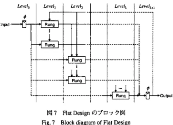
(4) X001. 11. ;. n! v")02 |. ,. |. ( Y002. j. Y002. 1|. | X001. ( Y003 )—I. I. 1|. ,. ,. < Y003 )—|. %. X001. |—11. |. j. j X002 |. ( Y002 )—|. 1|. ,. ( Y001 )—|. I. j. ( Y001 )—|. (a)r—. Fig. 4. Three dependences to be considered. Input. ■■■. |*l 6 Fig. 6. h ^""9 n~** •|j. ••. — H Rung |- nLg-Uoutput. Levelized Design <D"/ O -v ^7 gj. W}7. Block diagram of Levelized Design. Fig. 7. Flat Design (D7n y tW Block diagram of Flat Design. \ LD. 4(a)). (H 4(b)). t S.. C. Flat Design (FD) t ^ (H 7) .. Levelj ^(DXtlte Level{{0 £ i < j). (H4(c)).. mi2) 1 fray. > Levelized Compiled Code simulation [12] t± <. T5.. 1 x. 3.7. Leve/i, Leveljt .... Levelx. 3.6. Flat Design. LD •fttt. -46-.
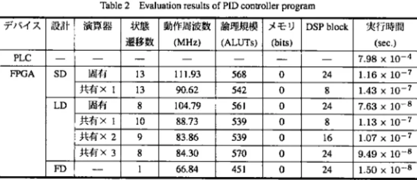
(5) M2 Table 2. Evaluation results of PID controller program. .. U X hX. 32. VIZ SD(H^) (C^LT 5.7. tz. £ — ^ y h f* > W X & StratixII EP2S60F672C5ES (48,352. ,. FD. .1. ALUT, memory 2,544,192 bit, DSP block 288 elements) t U. Altera Quartus II 6.0SP1 T*mWmtnttmfflk*fl»t> i ft.. (S^7 84%M/».. WM, %W, ffcW) <DM±£.f£%L% n £L. SSOTil&fcJtffll LT DSP Block tfffli'PtZ) ££&l£, ALUTs. xn" tTjkLfc. FPGA±O^ff^F^ (X. l£ SD(gppf) icMLX SD(^±^" xl) X 51%, LD(IIW) KlfcfLT. (worstcase) fc Lft. . PID f|9j. /^5. FX2NPLC-e©^fT^K«798MaccT*. 1303 ^^r. 16. 508^sectiAW^^a*ft5 END^^{Cck^. SD(H^). tT^ffflfCW LT 6879 ^^ ALUT T 1%,. DSP block T. *. .. FD T(J:. 1.5 fe%. L.. ,. T DSP Block &«'>f5 tf. siSM+I (ALUT) (i SD(@^) \Z xl) T 5%, LD(@^) (C^fLT LD(£W xl). ,. zfitf DSp Block. 5.. tt (a *±). plc. -47-. ALUTs (i. xl).
(6) IgVHDL £. Table 3. Evaluation results of sample ladder program. Table 4. Evaluation results of sample ladder program. 7—. [2]. M. A. Adamski and J. L. Monteiro: "From interpreted petri net spec ification to reprogrammable logic controller design," in Proc. IEEE Int'l Symp. Industrial Electronics (ISIE 2000), vol. 1, 2000, pp. 13-. Altera StratixII FPGA ±fc*. 19.. [3]. M. Wegrzyn, M. A. Adamski, and J. L. Monteiro: "The application of reconfigurable logic to controller design," Control Engineering Prac-. &, Sequential Design (SD)T& PLC £J±tfcLT$J 1800 f&. Flat. tice, vol. 6, pp. 879-887, 1998.. Design (FD) Ttt SD CD 5.6 ^ (PLC 0$ 10000 *B) ©iffiW bb*. [4]. A. Wegrzyn and M. Wegrzyn: "Petri net-based specification, anal ysis and synthesis of logic controllers," in Proc. IEEE Int'l Symp.. SD tf 3554 ALUT. FD ^ 2643 ALUT. Industrial Electronics (ISIE 2000), vol. 1, 2000, pp. 20-26. [5]. £ fd «:.. M. Ikeshita,. Y. Takeda,. H. Murakoshi,. N. Funakubo,. and I.. Miyazawa: "An application of FPGA to high-speed programmable controller, development of the conversion program from SFC to Verilog," in Proc. IEEE Int'l Conf. Emerging Technologies and Factory Automation (ETFA '99), vol. 2, 1999, pp. 1386-1390.. .. FD. [6]. I. Miyazawa, T. Nagao, M. Fukagawa, Y. Itoh, T. Mizuya, and T. Sekiguchi: "Implementation of ladder diagram for programmable controller using FPGA," in Proc. 7th IEEE Int'l Conf. Emerging Technologies and Factory Automation (ETFA '99), vol. 2, 1999, pp. 1381-1385.. [7]. S. Ichikawa, M. Akinaka, R. Ikeda, and H. Yamamoto: "Converting PLC instruction sequence into logic circuit: A preliminary study," in. Proc. IEEE Int'l Symp. Industrial Electronics (ISIE '06), 2006, pp. 2930-2935.. [8] [9] [10]. «F^ (0(2)16500029 ©. A^NM^^x^zstt, http://www.yashima-ne.co.jp. HMM$l$ixK.£tt, FX1S/FX1N/FX2N/FX1NC/FX2NC i/ U — X ■fin >?^ ^ yy7-i7;l/, 2006/11, JY992D62001 ver. L. HH^fKfc^zxft:, GX Developer Version8 ' — a T)l, 2006/10, SH080356 ver. S.. [11]. =.?£Mti&$ixK.'kti, GX Converter Version 2t^\ U— i -a7/K 2005/12, SH080122 ver. H.. [12] [1]. M. A. Adamski and J. L. Monteiro: "PLD implementation of logic controllers," in Proc. IEEE Int'l Symp. Industrial Electronics (ISIE '95), vol. 2, 1995, pp. 706-711.. -48-. M. Chiang and R. Palkovic, "LCC simulators speed development of. synchronous hardware," Computer Design, vol. 25, no. 5, pp. 87-92, 1986..
(7)
図


+2

関連したドキュメント
Those of us in the social sciences in general, and the human spatial sciences in specific, who choose to use nonlinear dynamics in modeling and interpreting socio-spatial events in
The object of the present paper is to give applications of the Nunokawa Theorem [Proc.. Our results have some interesting examples as
LLVM から Haskell への変換は、各 LLVM 命令をそれと 同等な処理を行う Haskell のプログラムに変換することに より、実現される。
Polarity, Girard’s test from Linear Logic Hypersequent calculus from Fuzzy Logic DM completion from Substructural Logic. to establish uniform cut-elimination for extensions of
Keywords: continuous time random walk, Brownian motion, collision time, skew Young tableaux, tandem queue.. AMS 2000 Subject Classification: Primary:
in [Notes on an Integral Inequality, JIPAM, 7(4) (2006), Art.120] and give some answers which extend the results of Boukerrioua-Guezane-Lakoud [On an open question regarding an
Variational iteration method is a powerful and efficient technique in finding exact and approximate solutions for one-dimensional fractional hyperbolic partial differential equations..
This paper presents an investigation into the mechanics of this specific problem and develops an analytical approach that accounts for the effects of geometrical and material data on
