• 検索結果がありません。

Investigation of Nanoparticles and Interface Effects on Organometal Halide Perovskite Solar Cells Fabricated by Wet Process

N/A
N/A
Protected

Academic year: 2021

シェア "Investigation of Nanoparticles and Interface Effects on Organometal Halide Perovskite Solar Cells Fabricated by Wet Process"

Copied!
12
0
0

読み込み中.... (全文を見る)

全文

(1)

Investigation of Nanoparticles and Interface Effects on Organometal Halide Perovskite Solar Cells Fabricated by Wet Process

著者 モハマド シャヒドゥザマン

著者別表示 MD Shahiduzzaman journal or

publication title

博士論文要旨Abstract 学位授与番号 13301甲第4480号

学位名 博士(学術)

学位授与年月日 2016‑09‑26

URL http://hdl.handle.net/2297/46582

Creative Commons : 表示 ‑ 非営利 ‑ 改変禁止 http://creativecommons.org/licenses/by‑nc‑nd/3.0/deed.ja

(2)

INVESTIGATION OF NANOPARTICLES AND INTERFACE EFFECTS ON ORGANOMETAL HALIDE PEROVSKITE SOLAR CELLS

FABRICATED BY WET PROCESS

A DISSERTATION

SUBMITTED TO THE DIVISION OF MATERIAL SCIENCE IN PARTIAL FULFILLMENT OF THE REQUIREMENTS FOR THE

DEGREE OF DOCTORATE IN PHILOSOPHY

by

MD. SHAHIDUZZAMAN REGISTRATION NO.: 1323132008 ADVISOR: DR. TETSUYA TAIMA

GRADUATE SCHOOL OF NATURAL SCIENCE & TECHNOLOGY KANAZAWA UNIVERSITY

KAKUMA, KANAZAWA, JAPAN

SEPTEMBER, 2016

(3)

Abstract

Hybrid organometal halide perovskites such as methylammonium lead iodide (CH

3

NH

3

PbI

3

) are attracting considerable attention as energy-efficient light absorber materials for photovoltaic applications owing to their solution processability, tunable bandgap, strong absorption coefficients and cost effectiveness. We, (Dr. Taima research group) developed nano-structured, and interlayer controlled method. This interlayer method, I applied to planar heterojunction (PHJ) perovskite solar cells. My thesis presented two different approaches that are aimed at contributing to the development of PHJ perovskite solar cells.

We prepared CH

3

NH

3

PbI

3

nanoparticles (NPs) for the first time using a simple spin- coating method by incorporating a small amount (1~10 wt %) of an ionic liquid (IL) 1- hexyl-3-methylimidazolium chloride in 25 wt % solution of CH

3

NH

3

PbI

3

in N,N- dimethylformamide (DMF) onto the compact-TiO

x

/ITO substrates to control size and shape of NPs. Compact-TiO

x

films were prepared by chemical bath deposition (CBD) according to the procedure described by Kuwabara et al. (Organic electronics 11, 2010, 1136). The CH

3

NH

3

PbI

3

NP thin films were uniform and free of pin holes, and the excellent morphology was due to the addition of IL. The small-sized CH

3

NH

3

PbI

3

NPs (~350 nm) with superior optical absorption properties have been obtained with 3 wt % of IL in the medium, as compared to the other compositions with wt % of 1, 7 and 10. As a result, a maximum power conversion efficiency (PCE) of 2.81% was obtained with the solar cell using 3 wt % of IL in a solution. The effect of viscosity of varying ILs have also been investigated. Low viscosity of ILs together with completely dissolve in CH

3

NH

3

PbI

3

solution were playing a significant role in controlling the morphology of resulting NPs.

The preliminary results are promising for the fabrication of solar cells based on CH

3

NH

3

PbI

3

NPs using a device configuration of ITO/TiO

x

/ CH

3

NH

3

PbI

3

NPs/ spiro- OMeTAD/Ag. We also expect that the results will open a pathway towards a better understanding for the fabrication, modification and enhancement of the performance of solar cells with CH

3

NH

3

PbI

3

NPs. In the present case, we assume a hindering effect followed by impact on charge dissociation, transport, and/or recombination on the device performances due to the residual IL content remained on the CH

3

NH

3

PbI

3

NP films.

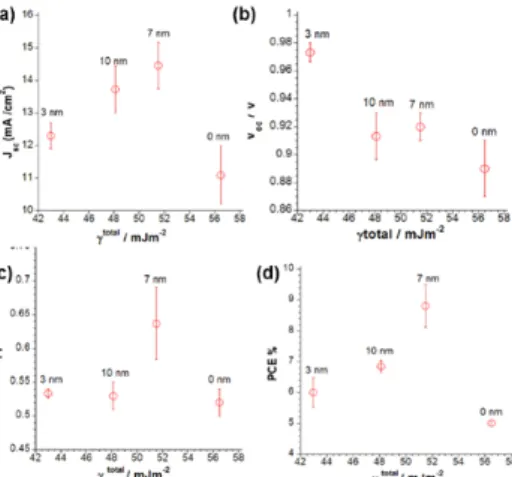
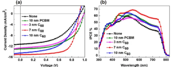
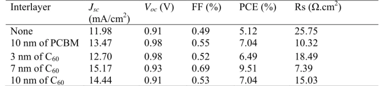
And, we fabricated PHJ type perovskite solar cells with enhanced efficiency by introducing fullerene (C

60

) interlayers with thicknesses of 0, 3, 7 and 10 nm between air- stable amorphous compact TiO

x

and CH

3

NH

3

PbI

3

layers. The modified morphology obtained by inclusion of C

60

improved the surface energy properties of the cells in terms of enhanced photocurrent. Atomic force microscopy verified the correlation between the surface energy and phase morphology of the PHJ solar cells. The introduction of a C

60

interlayer between CH

3

NH

3

PbI

3

and TiO

x

layers increased the content of photogenerated charge carrier sites, as well as lowering the accumulation and trapping of photogenerated charges at the TiO

x

interface. The optimum thickness of C

60

interlayer was 7 nm, for which a maximum PCE of 9.51% was obtained.

Keywords: Nanoparticles; Ionic liquid; Spin-coating method; Organometal halide

perovskite; CH

3

NH

3

PbI

3

; Interlayer; Fullerene (C

60

).

(4)

Results and discussion

We introduced varying wt % of IL (chemical structure: Fig. 1a) as a morphology controlling additive with CH

3

NH

3

PbI

3

in the DMF solution. We obtained a clear yellow- orange colored homogeneous solution having no aggregate or NPs (Fig. 1b).

Figure 1.1. (a) Chemical structure of 1-hexyl-3-methylimidazolium chloride (HMImCl), (b) Homogeneous mixture solution of CH

3

NH

3

PbI

3

and IL.

CH

3

NH

3

PbI

3

NPs having spherical morphology, was formed as shown in Fig. 1.2 (a, b and c), in the presence of 1, 3 and 7 wt % IL with respective diameters of 540, 350 and 600 nm. In contrary, the addition of high concentration of 10 wt % IL has resulted in irregular aggregation of CH

3

NH

3

PbI

3

blocks as shown in Fig. 1.2d. We observed unchanged shapes but changed morphology of NPs with varying wt % of IL to the solution.

The observation was similar to a previous report by Duan et al.

1

which confirms that the sizes and morphologies of the crystals depended on the concentration of the ionic liquid.

The observation was further confirmed by the AFM analysis. The AFM image (Fig.

1.3e-f), showed the aggregated morphology of NPs with non-uniform distribution for 7 and 10 wt % IL in solution, while the morphology was well developed for 1 and 3 wt % IL in solution as shown in Fig. 1.3c-d, respectively. The root-mean-square (RMS) roughness of the CH

3

NH

3

PbI

3

films were respectively 21.19, 17.83, 71.25 and 121.29 nm at 1, 3, 7 and 10 wt % of IL. The RMS roughness was smoother with 3 wt % IL in solution as compared to the other compositions. Air stable amorphous compact-TiO

x

layer having smooth morphology of 30 nm thickness was achieved in one-time operation as shown in the AFM analysis (Fig. 1.3a). The RMS roughness value of the resulting film was 4.13 nm.

Figure 1.2. The SEM images of the CH

3

NH

3

PbI

3

NPs prepared in the presence of varying

concentration of IL: (a) 1 wt %, (b) 3 wt %, (c) 7 wt %, and (d) 10 wt %.

(5)

Figure 1.3. The AFM images of (a) TiO

x

film; (b) As-deposited CH

3

NH

3

PbI

3

small clusters prepared at RT and CH

3

NH

3

PbI

3

NPs with varying concentration of IL: (c) 1 wt %, (d) 3 wt %, (e) 7 wt %, and (f) 10 wt %.

The UV-Vis spectra of CH

3

NH

3

PbI

3

films with varying wt % of IL cast on glass/ITO/

compact-TiO

x

substrates are shown in Fig. 1.4. The absorption spectrum of DMF was discovered at around 263 nm (not shown in Figure), while it was at 340 nm for only IL.

The optical properties of CH

3

NH

3

PbI

3

NPs depend on the size and the shape of the particles.

The absorption peaks were observed at around 493, 550, 520 and 525 nm in the system with 1, 3, 7 and 10 wt % IL, respectively, which corresponded to NPs, in accordance with the observation from Ayi, et al.

2

The sharp absorption peaks for the spherical NPs also indicated a fairly uniform shape and size of NPs.

Figure 1.4. The UV-Vis spectra of the CH

3

NH

3

PbI

3

films processed with varying wt % of IL as well as only IL. Inset photographs show CH

3

NH

3

PbI

3

films prepared with varying concentration of IL: (a) 1 wt %, (b) 3 wt %, (c) 7 wt %, and (d) 10 wt %.

It was clear that the concentration of IL played a vital role on the sizes, shapes and

morphologies of the CH

3

NH

3

PbI

3

NPs. A uniform CH

3

NH

3

PbI

3

NPs with well-defined

morphologies have been obtained in the presence of a small amount of IL as additive

(Figure 1.2a-d). When the amount of the IL increased to 7 wt %, we obtained spherical

CH

3

NH

3

PbI

3

NPs (Fig. 3.2c) having approximately 600 nm diameter. In contrast, 3 wt % of

(6)

IL was the optimum condition leading to the formation of uniform CH

3

NH

3

PbI

3

NPs with a well-controlled spherical NPs with approximate diameter of 350 nm (Fig. 3.2b). However, when the amount of IL was increased to 10 wt %, we obtained amorphous CH

3

NH

3

PbI

3

blocks formed by irregular aggregation of small particles (Fig. 1.2d). We attributed it to the viscosity of the IL-DMF medium. A similar observation for IL-water medium was reported by Wu et al.

3

and the exponential expression used to express such characteristics were modified to fit into our system:

exp (1)

In Eq (1), is the mole fraction of DMF, is a characteristic constant of the mixture, and is the viscosity of the pure IL. The empirical equation point out that the viscosity of IL-DMF mixtures is increased exponentially when the mole fraction of DMF ( ) is decreased. When the amount of IL is increased, the viscosity of the system increases and the diffusion of the resulting complexes hindered. The resulting uniform thin film with good morphology was due to the presence of the IL.

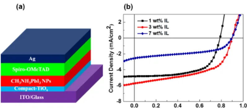
Figure 1.5a showed the device configuration of solar cells based on CH

3

NH

3

PbI

3

NPs.

The current density versus voltage (J-V) characteristics of CH

3

NH

3

PbI

3

NPs based solar cells as obtained by using the varying concentration of IL (1, 3 and 7 wt %) and were measured at AM 1.5G illuminations are shown in Figure 1.5b. The photovoltaic devices prepared with 1 wt % IL-doped CH

3

NH

3

PbI

3

NPs showed a short-circuit current density (J

sc

) of 4.84 mA/cm

2

. An increase in the J

sc

value to 5.74 mA/cm

2

was observed for the photovoltaic device prepared using 3 wt % IL-doped CH

3

NH

3

PbI

3

NPs, while the J

sc

value is decreased to 2.56 mA/cm

2

for 7 wt % doping of IL. The power conversion efficiency (PCE) is also followed the similar trend of the J

sc

values, showing a higher PCE of 2.81%

for the photovoltaic device of 3 wt % IL-doped CH

3

NH

3

PbI

3

NPs. All the parameters measured to study the performances of solar cells are summarized in Table 1. Optimization of the concentration with the 3 wt % of IL, we achieved CH

3

NH

3

PbI

3

NPs having more uniform shape, size, morphology which showed maximum PCE. Currently, we assume a hindering effect followed by the impact on charge dissociation, transport, and/or recombination on the device performances due to the residual IL content within the CH

3

NH

3

PbI

3

NPs. Hence, performance improvement experiments are underway to ensure the complete removal of IL-contents from the CH

3

NH

3

PbI

3

NPs films.

Table 1. Summary of cell performances of ITO/Compact-TiO

x

/CH

3

NH

3

PbI

3

NPs/Spiro- OMeTAD/Ag

Wt % of

IL J

sc

/mAcm

-

2

V

oc

/V FF PCE %

1 4.84 0.78 0.64 2.44

3 5.74 0.89 0.55 2.81

7 2.56 0.89 0.50 1.14

(7)

Figure 1.5. (a) Device configuration of solar cells based on CH

3

NH

3

PbI

3

NPs; (b) The J-V characteristics obtained for the solar cells based on CH

3

NH

3

PbI

3

NPs.

And, in this work, we modify the surface characteristics of air-stable amorphous TiO

x

layers by inserting fullerene (C

60

) as an interlayer in PHJ solar cells and investigate the effect of the thickness of the C

60

interlayer on the morphology and power conversion efficiency (PCE) of the resulting devices. Varying the thickness of the C

60

interlayer between 0 and 10 nm allows us to control the surface energy of the cells over a wide range of values. A correlation between the surface energy and PCE in PHJ solar cells is established, offering the possibility to enhance device performance. PCE is enhanced by the increased photocurrent that is obtained by tuning surface energy through optimization of morphology.

The AFM image in Fig. 1.6(a) reveals that a uniformly distributed, compact-TiO

x

amorphous layer with a thickness of 60 nm was obtained from two deposition cycles. The root-mean-square (RMS) roughness of this film was 4.21 nm. Fig. 1.6(b), (c) and (d) show the uniformly distributed morphologies of the C

60

interlayers with thicknesses of 3, 7 and 10 nm, respectively, which have respective RMS roughness values of 4.12, 3.31 and 8.28 nm. The RMS roughness was smoother with 7 nm C

60

film as compare to the other film thickness. The better morphology of 7 nm C

60

interlayer can be collected electrons more efficiently at the CH

3

NH

3

PbI

3

/compact-TiO

x

interface, thus degrading the interfacial barrier.

As compared to other conditions, the morphology becomes more rough (Figure 1.6 b and d),

which is expected to reduce the interfacial area. The resultant reduction of charge

generation then will degrade the J

SC

(and hence also the PCE). The variation of the device

performance with respect to the surface energy observed in Figure 1.6 and 1.7 can be

explained in terms of morphology. The films without C

60

showed incomplete surface

coverage and were composed of non-uniform large ribbon-like crystals (Fig. 1.6(e)).

(8)

Figure 1.6. AFM images of (a) a TiO

x

film; C

60

layers with a thickness of (b) 3, (c) 7, and (d) 10 nm; (e) TiO

x

/CH

3

NH

3

PbI

3

film and (f) TiO

x

/C

60

(7 nm)/CH

3

NH

3

PbI

3

film

RMS roughness values of the CH

3

NH

3

PbI

3

films with and without a 7-nm-thick C

60

layer were 71.78 and 101.78 nm, respectively, so the 7-nm-thick C

60

interlayer decreased the roughness of the overlying CH

3

NH

3

PbI

3

film. To produce highly efficient PHJ perovskite solar cells, it has been shown that uniform morphology and high crystallinity are very important.

4, 5

In this respect, both the morphology and crystallinity of perovskite solar cells have been improved by inclusion of a C

60

interlayer. The enhanced crystallization facilitates the more charge transfer efficiency between interlayer and the CH

3

NH

3

PbI

3

.

Figure 1.7 (a), (b) and (d) show J

sc

, FF and PCE of the cells, respectively, as a function of TiO

x

surface energy in the range from 43 to 51.5 mJ m

-2

. J

sc

, FF and PCE all exhibited the same overall trend with respect to surface energy, with maximum values at an intermediate surface energy. The highest PCE (9.51%), J

sc

(15.17 mA/cm

2

) and FF (0.69) were observed for the device with a surface energy of 51.5 mJ m

-2

containing a 7-nm-thick C

60

interlayer. The optimized morphology obtained by surface-energy modification enhanced the photocurrent of the corresponding solar cell. In contrast, the open circuit voltage (V

oc

) did not show any significant changes with respect to the surface energy, as shown in Figure 5.5b. AFM analysis verified the correlation between the surface energy and phase morphology of the PHJ solar cells.

Figure 1.7. Characteristics of CH

3

NH

3

PbI

3

solar cells as a function of the surface energy of

the C

60

layer: (a) short-circuit current density, J

sc

, (b) open-circuit voltage, V

oc

, (c) fill

factor, FF, and (d) power conversion efficiency, PCE. Error bars show plus-or-minus one

standard deviation from the mean.

(9)

Figure 1.8(a) further compares the device characteristics of the PHJ CH

3

NH

3

PbI

3

solar cells by showing J-V curves measured for cells with and without a C

60

interlayer. A solar cell with similar architecture fabricated using PCBM as the interlayer instead of C

60

was used as a reference. The device without a C

60

interlayer exhibited a J

sc

of 11.98 mA/cm

2

, V

oc

of 0.91 V, FF of 0.49, and PCE of 5.12%. Such poor device performance was caused by a contact barrier that prevented efficient electron injection at the interface between CH

3

NH

3

PbI

3

and TiO

x

, which led to a large leakage current and the recombination of charge carriers. Conversely, incorporation of a 7-nm-thick C

60

interlayer caused J

sc

to increase to 15.17 mA/cm

2

, while it was 13.47 mA/cm

2

for the device with a 10-nm-thick PCBM interlayer. The FF was enhanced from 0.49 to 0.69 and 0.55 upon the inclusion of 7-nm-thick C

60

and 10-nm-thick PCBM layers, respectively. The enhancement of J

sc

and FF induced by the 7-nm-thick C

60

interlayer was attributed to the lowering of the injection barrier at the interface between CH

3

NH

3

PbI

3

and compact TiO

x

, which decreased the series resistance from 25.75 to 7.39 Ωcm

2

. This result indicates that the incorporation of a C

60

interlayer on the TiO

x

/ITO glass substrate enhanced charge carrier extraction from the perovskite layer to the ITO electrode, which led to the improvement of J

sc

and PCE of the resulting films. PCE increased considerably from 5.12% to 9.51% upon the insertion of a 7- nm-thick C

60

interlayer between the CH

3

NH

3

PbI

3

and TiO

x

layers.

Incident photon-to-current conversion efficiency (IPCE) curves of devices with and without interlayers are presented in Fig. 1.8(b). The enhanced PCEs of the devices with a C

60

or PCBM layer are consistent with the higher IPCE values of these devices than that of the cell without an interlayer. The photocurrents determined from the IPCE data were 11.02, 13.12 and 15.17 mA/cm

2

for cells without an interlayer, and with an interlayer of PCBM (10 nm) and C

60

(7 nm), respectively. The PHJ CH

3

NH

3

PbI

3

solar cells exhibited a spectral response that extended from the visible to the near-infrared region with a broad, flat peak intensity of absorption around 60%–70% at approximately 380–750 nm. The higher IPCE

value of the

Figure 1.8. (a) Current density–voltage (J-V) characteristics and (b) incident photon-to- current conversion efficiency (IPCE) spectra of devices without and with C

60

interlayers of different thicknesses.

device with a 7-nm-thick C

60

layer in the visible-to-near-infrared wavelength region than

those of the other devices suggests that the 7-nm-thick C

60

interlayer collect electrons more

(10)

efficiently at the CH

3

NH

3

PbI

3

/TiO

x

interface because it successfully lowers the interfacial energy barrier.

Table 2. Performance of cells with the structure ITO/compact-TiO

x

/C

60

or CH

3

NH

3

PbI

3

/Spiro-OMeTAD/Ag.

The effect of incorporation of a C

60

interlayer on the performance enhancement of PHJ perovskite solar cells was clarified by including C

60

interlayers of different thickness.

The parameters of these solar cells are summarized in Table 2. The results from these measurements strongly supported our concept that manipulating the surface energy of the C

60

interlayer can enhance device performance. The above discussion indicates a clear relationship between surface energy, perovskite film morphology and PCE.

Conclusions

We succeeded to prepare CH

3

NH

3

PbI

3

NPs with better morphology by introducing an ILs of varying wt % by using a simple spin-coating method. The results showed that the size and shape of NPs can be controlled or modified by using varying wt % of IL as additive in the DMF solvent medium. The small-sized CH

3

NH

3

PbI

3

NPs (~350 nm) with superior optical absorption properties have been obtained with 3 wt % of IL in the medium, as compared to the other compositions with wt % of 1, 7 and 10. As a result, a maximum PCE of 2.81% was obtained with the solar cell using 3wt % of IL in a solution.

We tuned the surface energy of TiO

x

films by introducing C

60

interlayers of varying thickness into PHJ perovskite solar cells to enhance their PCE. The surface energy of the C

60

interlayer strongly affected the resulting device performance. The highest PCE was observed for the device fabricated with a 7-nm-thick C

60

interlayer, which had a surface energy of 51.5 mJ m

-2

. The C

60

interlayer between the perovskite and TiO

x

layers increased the content of photogenerated charge carrier sites and lowered the accumulation and trapping of photogenerated charges at the TiO

x

interface. These effects increased J

sc

, FF and PCE of the cells containing a C

60

interlayer compared with those of solar cells without an interlayer. The maximum PCE of 9.51% for the device with a 7-nm-thick C

60

interlayer can be attributed to its low series resistance caused by better energy level alignment with the contacts, which lowered the interfacial barrier.

Interlayer J

sc

(mA/cm

2

)

V

oc

(V) FF (%) PCE (%) Rs (Ω.cm

2

)

None 11.98 0.91 0.49 5.12 25.75

10 nm of PCBM 13.47 0.98 0.55 7.04 10.32

3 nm of C

60

12.70 0.98 0.52 6.49 18.49

7 nm of C

60

15.17 0.93 0.69 9.51 7.39

10 nm of C

60

14.44 0.91 0.53 7.04 15.03

(11)

References

1.  X. Duan, J. Lian, J. Ma, T. Kim and W. Zheng, Cryst. Growth Des., 2010, 10, 4449‐4455. 

2.  A. A. Ayi, C. A. Anyama and S. S. Etuk, J. Appl. Chem., 2014, 2, 26–32. 

3.  L. Wu, J. Lian, G. Sun, X. Kong and W. Zheng, Eur. J. Inorg. Chem., 2009, 2009, 2897‐2900. 

4.  M. Liu, M. B. Johnston and H. J. Snaith, Nature, 2013, 501, 395‐398. 

5.  N. J. Jeon, J. H. Noh, Y. C. Kim, W. S. Yang, S. Ryu and S. I. Seok, Nat. Mater., 2014, 13, 897‐

903. 

(12)

Figure 1.2. The SEM images of the CH 3 NH 3 PbI 3  NPs prepared in the presence of varying  concentration of IL: (a) 1 wt %, (b) 3 wt %, (c) 7 wt %, and (d) 10 wt %
Figure 1.3. The AFM images of (a) TiO x  film; (b) As-deposited CH 3 NH 3 PbI 3  small clusters  prepared at RT and CH 3 NH 3 PbI 3  NPs with varying concentration of IL: (c) 1 wt %, (d) 3  wt %, (e) 7 wt %, and (f) 10 wt %
Figure 1.5. (a) Device configuration of solar cells based on CH 3 NH 3 PbI 3  NPs; (b) The J-V  characteristics obtained for the solar cells based on CH 3 NH 3 PbI 3  NPs
Figure 1.7  (a), (b) and (d) show J sc , FF and PCE of the cells, respectively, as a  function of TiO x  surface energy in the range from 43 to 51.5 mJ m -2
+3

参照

関連したドキュメント

• Transplantation model systems were established in the zebrafish and clonal ginbuna carp to evaluate the activity of hematopoietic cells. • Hematopoietic stem cells

Two grid diagrams of the same link can be obtained from each other by a finite sequence of the following elementary moves.. • stabilization

Standard domino tableaux have already been considered by many authors [33], [6], [34], [8], [1], but, to the best of our knowledge, the expression of the

In this section we generalize some of the results of Sommers [16] on bounded dominant regions of Cat and positive filters in + to bounded dominant regions of A m and

q-series, which are also called basic hypergeometric series, plays a very important role in many fields, such as affine root systems, Lie algebras and groups, number theory,

Comparing the Gauss-Jordan-based algorithm and the algorithm presented in [5], which is based on the LU factorization of the Laplacian matrix, we note that despite the fact that

Recently, Velin [44, 45], employing the fibering method, proved the existence of multiple positive solutions for a class of (p, q)-gradient elliptic systems including systems

Atherosclerosis is a disease of the vasculature that is characterized by an accumulation of lipid-laden immune cells and apoptotic cells in the arterial wall.. Recently, the