Single-Pole-Type head showing a large recording field suitable for 1 Tbpsi with discrete track media
Y. Kanai
a,*, H. Watanabe
a, H. Muraoka
band Y. Nakamura
ba Niigata Insititute of Technology, 1719 Fujihashi, Kashiwazaki 945-1195, Japan
b Tohoku University, 2-1-1 Katahira, Aoba-ku, Sendai 980-8577, Japan
--- --- Abstract
Cusp-field Single-Pole-Type (CF-SPT) head that has a main pole with double-sided tapers that generates a large field ( > 20 kOe) is described. An FEM analysis of the head with a discrete-track media has been carried out to realize a higher track density recording. DC stray field for various combinations of recording layer and non-magnetic layer widths are derived. It is found that the recording field at the track center becomes larger as the magnetic layer width gets smaller, however, the stray field to the adjacent tracks can not be reduced by introducing the discrete-track media.
Keywords: Perpendicular magnetic recording; Recording write heads; Finite-Element methods; Magnetic field calculations
--- ---
1. Introduction
Perpendicular recording with an areal density of 170 Gb/in2 (876 kbpi x 194 ktpi) has been reported using the combination of a single-pole-type (SPT) head and a double-layered medium [1]. Conceptual studies for areal densities of 1 Terabits/in2 have also been shown [2]. We have shown previously using an FEM model [3] that the cusp-field single-pole-type (CF-SPT) head [4] with a tapered main pole [5], tapered return path on the trailing side, and side shield yokes [6] generates a large recording field, a large recording field gradient [7] and a small stray field at the adjacent tracks as well as a recording field distribution robust for skew.
This paper describes an SPT head that has a main pole with double-sided tapers that generates a large field.
An FEM analysis of the head with a discrete track media to realize a higher track density recording is also shown. It is noted that the recording field becomes larger for narrower recording track width. It is also shown that the stray field to the adjacent tracks can not
be reduced by introducing the discrete-track media
2. FEM model calculations 2.1. Analysis method
Throughout this paper the commercial FEM software JMAG-Studio [8] has been used to analyze the head field. Material nonlinearity is considered in the calculations, while dynamic phenomena and micromagnetics are neglected.
2.2. Analysis of SPT head with continuous medium
We have previously proposed that the SPT head with a tapered main pole, tapered return path on the trailing side, and side shield yokes for terabit condition as shown in Figs. 1. The track width was assumed to be 37 nm. The main pole thickness at ABS, magnetic spacing, andrecording layer thickness were 50 nm, 6.5 nm, and 9 nm respectively [2]. The saturation flux density of the soft materials and the initial permeability were assumed to be 24 kG and 1000, respectively, while the recording layer was assumed as a linear material with permeability of 2 [9]. FEM calculations has shown that the proposed Paper number: 01aB-03
---
*Corresponding author. Tel.: +81-257-22-8127; fax: +81- 257-22-82266.
E-mail address: [email protected] (Y. Kanai).
head generates recording field strength of 18.0 kOe, field gradient of > 400 Oe/nm at 11 nm from ABS, and a field distribution robust for skew as shown in Fig. 3. In the figure, the outermost boundary corresponds to 2 kOe and the head structure at ABS is shown. Note that the width of the frame of the figure is 400 nm. In addition to this structure, various tapered main poles can be assumed. The main pole with taper on leading side as shown in Fig. 4 generates larger field (19.4 kOe), however, stray field is also larger due to the absence of
Fig. 1. Schematic structure of CF-SPT head with side shields.
Main pole – side shield spacing was 20 nm.
Fig. 2. Cross sectional view of CF-SPT head with tapered main pole on trailing side.
Leading side return path
Trailing side return path Side shield
Main pole Side shield Leading side return path
Trailing side return path Side shield
Main pole Side shield
Fig. 3. Calculated field distribution at the medium surface for conventional continuous medium with head structures having a trailing tapered main pole.
side shields at leading side as shown in Fig. 5. To obtain larger field and the field distribution robust for skew, a main pole with double-sided taper as shown in Fig. 6 can be assumed. Note that, when D = 0, 10, 20, and 30, throat height in Fig. 1 are 20, 30, 40, and 50 nm, respectively.Among the parameters shown in Fig. 6, the throat height, D is most critical. Fig. 7 shows the DC recording field vs. magnetomotive force for various D’s.
The strong dependency of field strength on D is found, therefore, the optimization of structure which is robust for variation of D is necessary. In table 1, the calculated recording field strengths are shown for various structures. Increasing the size of the gaps, GT and GL, gives a larger field, but it causes the field gradient to deteriorate. For the calculation we used the values D = 0, GT = GL = 50 nm (model d), and magnetomotive force (MMF) = 0.1 AT, and have obtained a maximum recording field of 22.5 kOe, in association with an excellent recording field gradient of > 400 Oe/nm.
Despite the strong field, the side-writing field at the adjacent track center was only 21 % of that at the home track center. The small pole area at ABS gives a very narrow recording pulse width, so that there is only a small skew effect as shown in Fig. 8.
Fig. 4. Schematic structure of CF-SPT head with tapered main pole on leading side.
Leading side return path
Side shield Side shield
Trailing side return path Main pole
Leading side return path
Side shield Side shield
Trailing side return path Main pole
Fig. 5. Calculated field distribution at the medium surface for conventional continuous medium with head structures having a leading tapered main pole.
Fig. 6. Cross sectional view of CF-SPT head with tapered main pole on both sides with various parameters.
0 5 10 15 20 25
0 0.1 0.2 0.3
Magnetmotive force [AT]
DC recording field [kOe]
D = 0 nm 10 nm 20 nm 30 nm
Fig. 7. DC recording field vs. magetomotive force for various throat height D.
Table 1
DC recording field strength for various head structures with double-tapered main pole.
model GT GL taper angle leading shield trailing shield recording field
a 25 nm 25 nm 45 deg. no yes 22.6 kOe
b 25 nm 25 nm 45 deg. yes yes 21.4 kOe
c 25 nm 25 nm 30 deg. yes yes 20.2 kOe
d 50 nm 50 nm 45 deg. yes yes 22.5 kOe
Leading side return path
Side shield Side shield
Trailing side return path Main pole Leading side return path
Side shield Side shield
Trailing side return path Main pole
Fig. 8. Calculated field distribution at the medium surface for conventional continuous medium with head structures having a leading tapered main pole (model d).
2.3. Introduction of discrete track media
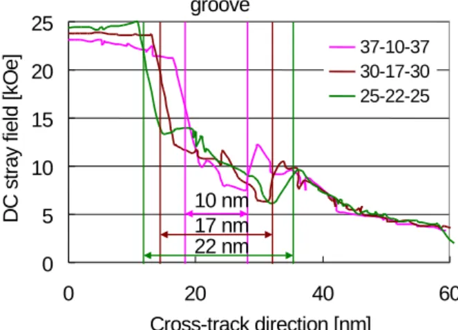
In order to realize a higher track density as well as the strong head field, a discrete track medium is one of the most promising solutions [10]. In Fig. 9, an FEM model of SPT head and discrete-track medium is shown, where the widths of the recording layer and non-magnetic layer (groove) are 37 nm and 10 nm, respectively. In Fig. 10, the variation of the DC stray field along the cross track direction is compared for continuous and discrete-track media. As has been pointed out in [10], the field strength on the discrete track is approximately5% larger than that of continuous medium by removal of neighboring magnetization due to the groove. Note that a larger stray field is observed at the adjacent discrete-track edges. In Fig. 11, DC Stray field for various combinations of recording layer/groove widths (37 nm + 10 nm + 37 nm; 30 nm + 17 nm + 30 nm; 25 nm + 22 nm + 25 nm) are shown, while the track pitch is set at constant, 47 nm. This shows that the recording field strength becomes larger as the width of the recording layer becomes narrower, and that the stray field at the edge of the adjacent track can not reduced.
In Fig. 12, the recording field distribution at the medium surface is shown, where the outermost boundary is H = 2 kOe. The combination of the double-tapered model and the discrete-track medium has advantage with regard to recording field strength
37 nm 10 nm Recording layer
Main pole Groove Side shield
37 nm SUL 10 nm Recording layer
Main pole Groove Side shield
SUL
Fig. 9. Pole tip region with discrete track medium.
0 5 10 15 20 25
0 20 40 60 80 100
Cross track direction [nm]
DC stray field [kOe]
Continuous
Discrete-track
Adjacent track Groove
Recording track
0 5 10 15 20 25
0 20 40 60 80 100
Cross track direction [nm]
DC stray field [kOe]
Continuous
Discrete-track
Adjacent track Groove
Recording track
Continuous
Discrete-track
Adjacent track Groove
Recording track
Fig. 10. DC stray field along cross-track direction for continuous and discrete-track media.
and sharp field distribution at the recording track edges, leading to higher track density recording. It is also seen that the discrete-track medium does not reduce the stray field and that the side shields are indispensable at the narrow track pitch. To improve the field distribution, an SPT head design reducing the stray field as well as arranging the recording layer and groove widths are necessary.
0 5 10 15 20 25
0 20 40 60
Cross-track direction [nm]
DC stray field [kOe] 37-10-37
30-17-30 25-22-25
10 nm 17 nm 22 nm groove
0 5 10 15 20 25
0 20 40 60
Cross-track direction [nm]
DC stray field [kOe] 37-10-37
30-17-30 25-22-25
10 nm 17 nm 22 nm 0
5 10 15 20 25
0 20 40 60
Cross-track direction [nm]
DC stray field [kOe] 37-10-37
30-17-30 25-22-25
10 nm 17 nm 22 nm groove
Fig. 11. DC stray field along cross-track direction for discrete-track media; various combinations of recording layer/
non-magnetic layer (groove) widths, where track pitch is fixed at 47 nm.
Leading side return path
Side shield Side shield
Trailing side return path Main pole Leading side return path
Side shield Side shield
Trailing side return path Main pole
Fig. 12. Calculated fielddistribution at the medium surface for discrete-track medium with head structures having a trailing tapered main pole. Recording layer and non-magnetic layer (groove) widths are 37 nm and 10 nm, respectively.
3. Conclusion
Cusp-field Single-Pole-Type (CF-SPT) head that has a main pole with double-sided tapers has been described.
An FEM analysis has shown that the proposed head generates a large field of 22.5 kOe. The recording field becomes larger as the recording layer width becomes narrower by the combination of proposed head with a discrete-track medium, while the stray field can not be reduced by the discrete-track media.
Acknowledgements
The authors wish to thank Drs. K. Yamakawa and K.
Ise, Akita Institute of Advanced Technology, Japan for their useful discussions, and appreciate the kind support by SRC, Japan. The authors also would like to acknowledge use of JMAG-Studio from The Japan Research Institute, Limited.
This work was supported in part by a Grant in Aid for the Japan Society for the Promotion of Science (#15,560,311) and Storage Research Consortium (SRC), Japan.
References
[1] S. Li, G. Loscheider, K. Gao, J. Putman, W. Zhu, S. Chen, G. Li, and S. Mao, “Transport Characteristics in some TMR recording heads with ultra-thin barriers,” 9th Joint MMM-Intermag Conf. (2004) FP-08.
[2] R. Wood, “The feasibility of magnetic recording at 1 terabit per square inch,” IEEE Trans. on Magn., 36 (2000) 36.
[3] Y. Kanai, R. Matsubara, H. Watanabe, H. Muraoka, and Y. Nakamura, “Recording field analysis of narrow-track SPT head with side shields, tapered main pole, and tapered return path for 1 Tb/in2,” IEEE Trans. on Magn.
39 (2003) 1955.
[4] K. Ise, K. Yamakawa, N. Honda, K. Ouchi, H. Muraoka, and Y. Nakamura, “CUSP field single pole head with high recording resolution,” INTERMAG EUROPE 2002 (2002) FB-03.
[5] M. Mochizuki, Y. Nishida, Y. Kawato, T. Okada, T.
Kawabe, and H. Takano, “Study on the write-head profile and intensity of narrow-track-width SPT head,” Journal of Magnetism and Magnetic Materials 235 (2001) 191.
[6] M. Mallary, A. Torabi, and M. Benakli, “One terabit per square inch perpendicular recording conceptual design,”
IEEE Trans. on Magn. 38 (2002) 1719.
[7] W. Xia, H. Muraoka, and Y. Nakamura, “High field gradient single pole head with a novel pole structure,”
IEEE Trans. on Magn. 38 (2002) 2216.
[8] JMAG-Works, Commercial software, The Japan
Research Institute, Ltd.
(http://www.jri.co.jp/pro-eng/jmag/e/jmg/index.html).
[9] R. H. Victora, J. Xue, and M. Patwari, “Areal density limit for perpendicular magnetic recording,” IEEE Trans.
Magn. 38 (2002) 1886.
[10] Y. Soeno, M. Moriya, K. Ito, K. Hattori, A. Kaizu, T.
Aoyama, M. Matsuzaki, and H. Sakai, “Feasibility of discrete track perpendicular media for high track density recording,” IEEE Trans. on Magn. 39 (2003) 1967.