INSTALLATION GUIDE
TB-2606 Terminal Block
This installation guide describes how to install and connect signals to the TB-2606 terminal block for use with the NI 2501 and NI 2503 PXI switch cards.
Contents
Introduction ... 1
What You Need to Get Started ... 2
Signal Names ... 2
Signal Connection ... 3
Installing Your Terminal Block ... 5
Installing the Analog Bus Plug ... 6
Specifications ... 8
Introduction
The TB-2606 consists of a printed circuit board with screw terminals. The terminal block connects directly to the front panel I/O connector of the NI 2501 or NI 2503.
The TB-2606 provides the necessary routing to configure the NI 2501 or NI 2503 as a 6× 4 two-wire matrix. The NI 2501 and NI 2503 have four 6× 1 two-wire multiplexers. The modules can internally connect the four 6× 1 multiplexers to create a 24 × 1 two-wire multiplexer. However, the TB-2606 is needed to provide the necessary wiring so the four 6× 1 multiplexers are configured as a 6 × 4 two-wire crosspoint matrix.
The TB-2606 provides screw terminal connections to the column and row inputs of the matrix. The front side of the terminal block has two additional connectors for connecting to the analog bus. You can use the low-voltage AB plug to connect the analog bus of adjacent switch cards.
Type Title Here 2 ni.com
What You Need to Get Started
You need the following to set up and use your terminal block:
❑
One of the following PXI switch cards:– NI 2501
– NI 2503
❑
NI 2501/2503 User Manual❑
TB-2606 terminal block❑
0.10 in. slotted screwdriver❑
No. 1 Phillips screwdriver❑
Wire cutters❑
Wire insulation stripper❑
Analog bus connectors (to connect to multiple cards)Signal Names
The TB-2606 provides the following screw terminal connections.
Name Pin Number Name Pin Number
R0- 27 C3- 30, 21, 13, 3 R0+ 61 C3+ 64, 55, 47, 37 R1- 26 C4- 29, 20, 12, 2 R1+ 60 C4+ 63, 54, 46, 36 R2- 10 C5- 28, 19, 11, 1 R2+ 44 C5+ 62, 53, 45, 35 R3- 9 AB0- 18 R3+ 43 AB0+ 52 C0- 33, 25, 16, 6 AB1- 17 C0- 67, 59, 50, 40 AB1+ 51 C1- 32, 24, 15, 5 EXTERNAL TRIGGER 41 C1+ 66, 58, 49, 39 SCAN ADVANCED 42 C2- 31, 23, 14, 4 GND 7, 56 C2+ 65, 57, 48, 38 CHSGND CONNECTOR SHELL
© National Instruments Corporation 3 Type Title Here
Signal Connection
See your NI 2501/2503 User Manual for examples of how to connect your signals. Refer to Figure 1 as you perform the following steps to connect your signals to your terminal block (the numbers in parentheses refer to items in Figure 1).
1. Remove the terminal block cover (1) by unscrewing the two cover screws (2) using the 0.10 in. slotted screwdriver.
2. Loosen or remove the strain relief bar (3) by loosening the two strain relief screws (10).
3. Use wire cutters and wire insulation strippers to strip the wire ends as necessary to connect them to screw terminals.
4. Loosen the screws in the screw terminals with the 0.10 in. slotted screwdriver.
5. Insert the stripped wires into the screw terminals. Tighten the screws with the 0.10 in. slotted screwdriver.
6. Connect safety ground or shield wires to the chassis ground connection tab (7) using the provided solder lug (6).
7. Tighten or replace the strain relief screws (10).
Type Title Here 4 ni.com
Figure 1. TB-2606 Parts Locator Diagram
1 Cover
2 Cover Screws (captive) 3 Strain Relief Bar
4 Chassis Connection Screws
5 Ground Lug Screw 6 Ground Solder Lug 7 Chassis Ground Tab
8 Connection to Switch Card 9 Analog Bus Connectors 10 Strain Relief Screws 1 2 8 4 4 9 10 7 6 5 3
© National Instruments Corporation 5 Type Title Here
Installing Your Terminal Block
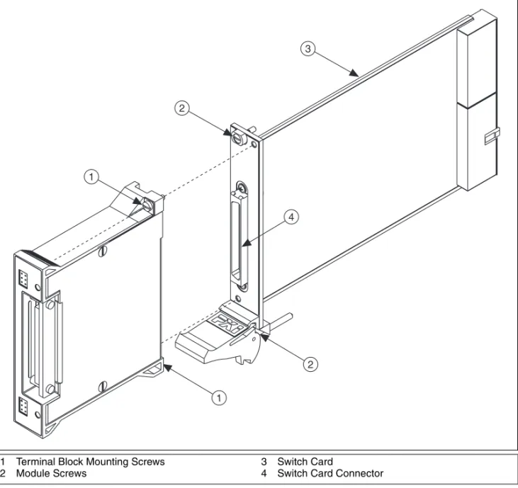
Refer to Figure 2 as you perform the following steps to connect the terminal block to the NI 2501 or NI 2503 connector (the numbers in parentheses refer to items in Figure 2).
Note The TB-2606 terminal block must be installed on the NI 2501/2503 switch card after the card is installed in the chassis.
1. Install the switch card (3) into the chassis and tighten the two module screws (2).
2. Guide the terminal block onto the switch card connector (4). 3. Tighten the two terminal block mounting screws (1).
Caution The connectors of both the switch card and the terminal block are polarized. You can attach them in only one way. Do not force the terminal block when inserting it into or removing it from the NI 2501 or NI 2503 connector.
Type Title Here 6 ni.com
Figure 2. Connecting the TB-2606 to the Switch Card
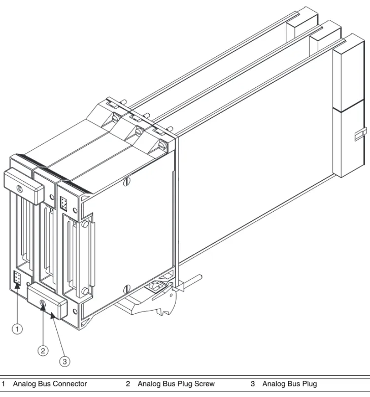
Installing the Analog Bus Plug
Refer to Figure 3 as you perform the following steps to install the analog bus plug. The cover should be attached to the terminal block before you connect the analog bus plug because the plug screws into the cover (the numbers in parentheses refer to items in Figure 3).
1. With two terminal blocks connected to boards in adjacent slots, connect the analog bus plug (3) into the analog bus connector (1) of each terminal block.
2. Tighten the screw (2) on the analog bus plug using the 0.10 in. slotted screwdriver.
1 Terminal Block Mounting Screws 2 Module Screws
3 Switch Card
4 Switch Card Connector
1 1 2 3 2 4
© National Instruments Corporation 7 Type Title Here
Figure 3. Installing the Analog Bus Plug
1 Analog Bus Connector 2 Analog Bus Plug Screw 3 Analog Bus Plug
1 2
National Instruments, NI, ni.com, and LabVIEW are trademarks of National Instruments Corporation. Refer to the Terms of Use section on ni.com/legal for more information about National Instruments trademarks. Other product and company names mentioned herein are trademarks or trade names of their respective companies. For patents covering National Instruments products, refer to the appropriate location:
Help»Patents in your software, the patents.txt file on your CD, or ni.com/patents.
© 1999–2007 National Instruments Corporation. All rights reserved. 372260B Nov07
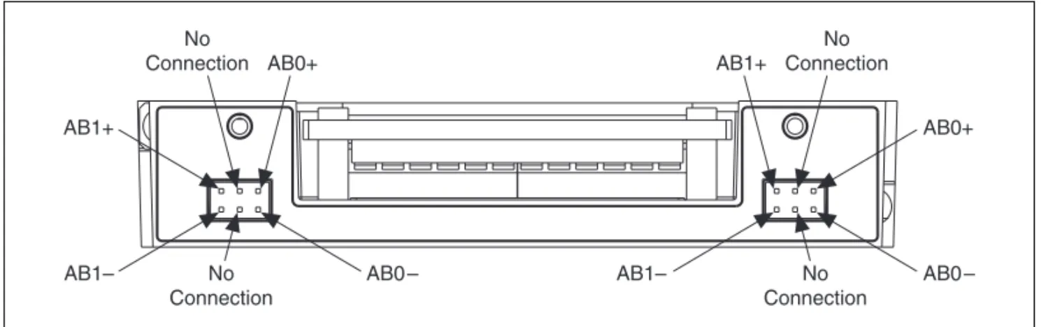
Analog Bus Connector
The front side of the terminal block has two connectors for connecting to the analog bus. The low-voltage analog bus plug can be used to connect the analog buses of adjacent switch cards, as shown in Figure 3. The signal connections for the analog bus are shown in Figure 4.
Figure 4. Analog Bus Connector
Specifications
Dimensions ...8.4 by 10.7 by 2.0 cm (3.3 by 4.2 by 0.80 in.) Max voltage
(signal + common mode) ...Each input should remain within 30 Vrms or 60 VDC of ground and
all other channels to eliminate the possibility of hazardous shock.
AB1+ AB0+ No Connection No Connection No Connection No Connection AB1+ AB1– AB1– AB0+ AB0 – AB0 –
取り付けガイド
TB-2606
端子台
この取り付けガイドでは、TB-2606端子台の取り付け方法、および NI 2501および NI 2503 PXIスイッチモジュールへの信号接続、使用する 方法について説明しています。目次
はじめに... 1 使用する前に... 2 信号名... 2 信号接続... 3 端子台を取り付ける... 5 アナログバス用プラグを取り付ける... 6 仕様... 8はじめに
TB-2606は、ネジ留め式端子を装備したプリント基板で構成されていま す。この端子台は、NI 2501またはNI 2503のフロントパネルI/Oコネク タに直接接続できます。 また、TB-2606はNI 2501およびNI 2503が 6 × 4の2線式マトリックス として構成される際に必要な接続経路を提供します。 NI 2501および NI 2503には、4つの2線式6 × 1マルチプレクサがあります。モジュー ルは4つの6 × 1マルチプレクサを内部的に接続し、2線式の24 × 1マル チプレクサを作成します。しかし、4つの6 × 1マルチプレクサを2線式 6 × 4クロスポイントマトリクスとして構成するには、TB-2606で必要な 配線を行う必要があります。 TB-2606ではマトリクスの列と行をネジ留め式端子で接続することができ ます。この端子台のフロント側には、アナログバスに接続できるコネクタ が2つあります。低電圧ABプラグを使用して隣接したスイッチカードの アナログバスに接続できます。TB-2606 端子台取り付けガイド 2 ni.com/jp
使用する前に
端子台の設定および使用には、以下が必要です。❑
次のPXIスイッチカードのいずれか1つ。 – NI 2501 – NI 2503❑
『NI 2501/2503ユーザマニュアル』❑
TB-2606 端子台❑
0.10 in. マイナスドライバー❑
No. 1 プラスドライバー❑
ワイヤカッター❑
ワイヤストリッパー❑
アナログバス用コネクタ(複数カードへの接続用)信号名
TB-2606のネジ留め式端子の接続は次のようになっています。 名前 ピン番号 名前 ピン番号 R0– 27 C3– 30, 21, 13, 3 R0+ 61 C3+ 64, 55, 47, 37 R1– 26 C4– 29, 20, 12, 2 R1+ 60 C4+ 63, 54, 46, 36 R2– 10 C5– 28, 19, 11, 1 R2+ 44 C5+ 62, 53, 45, 35 R3– 9 AB0– 18 R3+ 43 AB0+ 52 C0– 33, 25, 16, 6 AB1– 17 C0– 67, 59, 50, 40 AB1+ 51 C1– 32, 24, 15, 5 EXTERNAL TRIGGER 41 C1+ 66, 58, 49, 39 SCAN ADVANCED 42 C2– 31, 23, 14, 4 GND 7, 56 C2+ 65, 57, 48, 38 CHSGND CONNECTOR SHELL© National Instruments Corporation 3 TB-2606 端子台取り付けガイド
信号接続
信号接続の例については、『NI 2501/2503ユーザマニュアル』を参照し てください。次の手順に従って信号を端子台に接続する際には、図 1を参 照してください(括弧の中の番号は、図 1にあるアイテムを示す)。 1. 0.10 in.マイナスドライバーを使用して2つのネジ(2)を外し、端 子台のカバー(1)を取り外します。 2. 2つのストレインリリーフネジ(10)を緩めてストレインリリーフ バー(3)を緩める、または取り外します。 3. ワイヤカッターおよびワイヤストリッパーを使用して、ネジ留め式端 子に接続できるようにワイヤの両端の絶縁被覆を少し取り除きます。 4. ネジ留め式端子のネジを0.10 in. のマイナスドライバーで緩めます。 5. 裸線部分をネジ留め式端子に挿入します。 0.10 in. マイナスドライ バーでネジを締めます。 6. 付属の圧着端子(6)を使用して、接地ワイヤまたはシールドワイヤ をグランド接続用タブ(7)に接続します。 7. ストレインリリーフネジ(10)を締める、または取り付けます。 8. 端子カバー(1)を元のように取り付けて、ネジ(2)を締めます。TB-2606 端子台取り付けガイド 4 ni.com/jp 図 1 TB-2606部品位置のダイアグラム 1 カバー 2 カバー用ネジ(拘束) 3 ストレインリリーフバー 4 シャーシ接続用ネジ 5 接地端子用ネジ 6 接地用圧着端子 7 シャーシ接地用タブ 8 スイッチカードへの接続口 9 アナログバス用コネクタ 10 ストレインリリーフネジ 1 2 8 4 4 9 10 7 6 5 3
© National Instruments Corporation 5 TB-2606 端子台取り付けガイド
端子台を取り付ける
以下の手順を実行して端子台をNI 2501またはNI 2503コネクタに接続 する際は、図 2を参照してください(括弧の中の番号は、図 2にあるア イテムを示す)。 メモ NI 2501/2503スイッチカードをシャーシに取り付けた後に、TB-2606端子台を カードに取り付ける必要があります。 1. スイッチカード(3)をシャーシに取り付けて2つのモジュールネジ (2)を締めます。 2. 端子台をスイッチカードのコネクタ(4)に接続します。 3. 2つの端子台取り付けネジ(1)を締めます。 注意 スイッチカードと端子台の両コネクタには極性があります。そのため、一方向に のみ接続可能です。 NI 2501またはNI 2503コネクタに端子台を無理やり押し 込んだり力ずくで外したりしないでください。TB-2606 端子台取り付けガイド 6 ni.com/jp 図 2 TB-2606をスイッチカードに接続する
アナログバス用プラグを取り付ける
以下の手順に従ってアナログバス用プラグを取り付ける際は、図 3を参 照してください。アナログバス用プラグはカバーにネジ留めされるため、 プラグを接続する前にカバーを端子台に取り付けておく必要があります (括弧の中の番号は、図 3の中のアイテムを示す)。 1. 隣接するモジュールに取り付けられた2つの端子台において、 各端子台のアナログバス用プラグ(3)をアナログバス用コネクタ (1)に接続します。 2. アナログバス用プラグのネジ(2)を、0.10 in. マイナスドライバー で締めます。 1 端子台取り付けネジ 2 モジュールネジ 3 スイッチカード 4 スイッチカードコネクタ 1 1 2 3 2 4© National Instruments Corporation 7 TB-2606 端子台取り付けガイド 図 3 アナログバス用プラグを取り付ける 1 アナログバス用コネクタ 2 アナログバス用プラグのネジ 3 アナログバス用プラグ 1 2 3
National Instruments、NI、ni.com、およびLabVIEWはNational Instruments Corporation
(米国ナショナルインスツルメンツ社)の商標です。National Instrumentsの商標の詳細については、
ni.com/legal の「Terms of Use」セクションを参照してください。本文書中に記載されたその他の
製品名および企業名は、それぞれの企業の商標または商号です。National Instrumentsの製品を保護
する特許については、ソフトウェアに含まれている特許情報(ヘルプ→特許情報)、CDに含まれている
patents.txt ファイル、または ni.com/patents のうち、該当するリソースから参照してください。
©1999–2007 National Instruments Corporation. All rights reserved. 372260B-01 2007年11月