Translating OMT state diagrams with concurrency into SDL diagrams
Simona Vasilache and Jiro Tanaka
Institute of Information Sciences and Electronics University of Tsukuba, Tennodai 1-1-1,
Tsukuba, JAPAN Tel. (+81)-298-535165
^VLPRQDMLUR`#LSODELVWVXNXEDDFMS
ABSTRACT
Defining a complete methodology for the developing of an application is a challenge for many software engineering specialists. Although many such methodologies have been developed, few of them take into consideration all the aspects that can come up while developing complex applications. Many times, although a general outline for the methodology is being defined, for some important features, like concurrency, no handling solution is given. Our paper proposes a methodology that takes into consideration the concurrency while integrating the object-oriented analysis and specification design, by using the OMT methodology for the requirements analysis, an extension of OMT*, OMT*+, for system design and the formal description technique SDL for detailed design. We propose the translation of OMT state diagrams with concurrency into SDL diagrams with concurrent processes.
KEYWORDS
object-oriented methodology, OMT, object-oriented analysis, OMT*, SDL, concurrency
INTRODUCTION
Many object-oriented methodologies covering the development life cycle of an application have been proposed
during the last years. D. Sinclair et. al. integrated the object-oriented methodology OMT with the formal description technique SDL (Specification and Description Language) [6]. The methodology combines the strength of object-oriented analysis in the early phases and the strong back-end given by SDL.
Object Modeling Technique (OMT) is a popular methodology that focuses on creating a model of objects from the real world and then using this model to develop object-oriented software. SDL is a powerful specification language, based on an appealing graphical syntax, developed by CCITT-ITU. Because of its precise and complete definitions, it represents an efficient support for verification.
Since its version in 1992, SDL-92, it supports object-orientation, including also some features not seen in many other object-oriented languages (like specialization and redefinition of behaviour).
Involving OMT mainly in analysis and SDL in design, the methodology bridges the gap between these two important phases.
METHODOLOGY MILESTONES
The initial phase of the developing of the application is the requirements analysis. The fact that OMT is rigorous, but not formal makes it ideal for the initial system specification.
After the system requirements, we have to advance to system design. Since the system design will be translated into SDL,
which has a formally defined semantics, and considering that OMT is informal, we need a formally defined subset of OMT. Therefore, the model created in OMT is refined and transformed into OMT*. OMT* is a subset of OMT containing less, but well defined, syntactical constructs. The detailed design phase involves transforming the OMT*
description into SDL and developing the SDL description until it contains all the information needed to describe the functionality of the system.
OMT* AND ITS RESTRICTIONS
OMT is used for the requirements analysis. Because OMT does not have a defined semantics, it is not suited for design.
Only a small subset of OMT constructs have a clear and unambiguous representation in SDL. In order to meet the requirements of system design, a dialect of OMT, OMT*, has been introduced [6]. OMT* is a substantial subset of the most commonly used OMT constructs. The concepts in OMT* can be translated into SDL directly, according to certain transformation rules. The translation of an OMT*
specification into SDL is based on the definition of the transformational semantics given in [8]. OMT* represents a bridge between the informal description in OMT and the formal description in SDL.
The model created in OMT is refined through several iterations into OMT*. This involves, among other things, adding design details, removing classes which are part of the environment etc.
The syntax of OMT* contains a number of restrictions, compared to OMT. These restrictions are reflected both in the object model and dynamic model diagrams. The majority of these restrictions apply to the object model (e.g. the multiple inheritance is substituted with simple inheritance with aggregation). As for the dynamic model, the OMT*
state diagrams are restricted to state diagrams that do not contain concurrent substate diagrams. Since we consider concurrency a very important aspect, almost inherent in most of the dynamic model state diagrams, we propose the possibility to use and translate concurrent substate diagrams from OMT into SDL.
OMT’S DYNAMIC MODEL
In OMT, the dynamic model is the guide to concurrency.
State transition diagrams are used here; they are graphs with states represented as nodes and transition between states represented as arcs. State diagrams in OMT are refined into state diagrams in OMT*, but, as we have mentioned, OMT*
is restricted not to contain diagrams with concurrent substates. We propose the refinement of OMT diagrams into what we will call OMT*+ diagrams (OMT* diagrams with concurrency). The OMT state diagrams with concurrency are therefore refined and transformed into OMT*+ diagrams.
The same rules for transforming OMT* into SDL apply in the case of OMT*+.
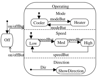
To make our idea more understandable, let us consider the example of a simple air conditioning system, operated with a remote control device (Fig. 1).
Fig.1. Remote control for an air conditioning system
The remote control device contains several buttons for mode (heater mode or cooler mode), speed (low, medium or high), direction of the air stream and On/Off. We consider a Controller as keeping control of the entire system. The OMT*+ state diagram of the Controller is represented in Fig.
2 [1].
Speed -Heater
-Cooler
2 4 1 3 -Low
-Med -High
Mode
On/Off
Fig. 2. State diagram of the Controller
A state diagram may contain several concurrent states that become active simultaneously whenever their superstate becomes active. Any transition into a state where concurrent subdiagrams are involved activates each one of the existing subdiagrams.
In our example, we have two possible states: Off and Operating. These states are activated alternatively whenever the On/Off button is activated.
Concurrency occurs within the Operating state, which is a combination of 3 concurrent substates: Mode, Speed and Direction. They all become active at the same time whenever the Operating state gets activated. Each of the concurrent states has a number of (non-concurrent) substates (Cooler, Heater for Mode, respectively Medium, High for Speed; for Direction, we have 4 possibilities: 1, 2, 3 or 4). Concurrency within a single composite state of an object is shown, just like in OMT, by partitioning the composite state into subdiagrams with dotted lines [5].
SDL REPRESENTATION
When representing a system in SDL, we have 3 hierarchical levels: system level (where the whole system is represented), block level (where the system is divided into smaller parts called blocks - each block contains a number of processes) and process level (the lowest level - each process contains a number of states).
Our air conditioning system contains 1 block (ACRemote) with 3 processes: one process for mode selection (SelectMode) , one for speed selection (SelectSpeed) and a
third one for direction selection (SelectDir).
The block level representation is shown in Fig. 3.
Speed
High speedBut
Low speedBut Med speedBut Heater Cooler modeBut
modeBut Mode Operating
ShowDirection Dir
Direction Off
on/offBut on/offBut
[ChgDir1, ChgDir2, ChgDir3 ChgDir4]
Fig.3 Block diagram representation
[SetSpeed]
SelectMode
[ChgMdHeat, ChgMdCool]
Block ACRemote
SelectSpeed
[ChgSpdLow, ChgSpdMed, ChgSpdHigh]
[SetDir]
SelectDir [SetMode]
Processes describe the dynamic behaviour of the system in SDL. The SelectMode, SelectSpeed and SelectDir processes correspond to the Mode substate, Speed substate and Direction substate, respectively, in the OMT*+ state transition diagram.
Processes in the system and the environment communicate with each other by sending signals through the signal routes and channels. Signals can be of two types: input signals and output signals. All the input and output signals have to be declared at the highest level they are going to be used.
Input signals result from the events that trigger the transition from a state into another state. In our case, what determines the transitions is the pressing of mode button, speed button and direction button. We will have, therefore, setMode, setSpeed and setDir as input signals.
The SetMode signal corresponds to the activation of the mode button (modeBut in the state transition diagram), SetSpeed corresponds to the activation of the speed button (speedBut), while SetDir corresponds to the pressing of the Direction button (Dir).
The output signals in our system are the ones sent to the environment, resulting from changing the state into Cooler or Heater (for the mode), Low, Med and High (for the speed) and 1,2,3,4 for the direction. In the SelectMode process, we have ChgMdHeat, ChgMdCool as output signals. For the SelectSpeed process, the output signals involved are:
ChgSpdLow, ChgSpdMed, ChgSpdHigh, while for the SelectDir process, the output signals are SetDir1, SetDir2, SetDir3 and SetDir4.
In the block level representation, the signals travel on signal routes and are transferred concurrently. We have no relative ordering of different processes except the ordering implied by the sending and the reception of signals. This implies that anytime any of the input signals mentioned can be sent and this has as effect the activation of the corresponding process, having no effect on the other processes. The processes involved are acting in this way concurrently.
In our example, any of the signals mentioned can be sent anytime; for instance, if the SetSpeed signal is sent (speedBut is pressed), the SelectSpeed process will be activated, while this will have no effect on the SelectMode and SelectDir processes.
CONCURRENCY IN SDL
The model of concurrency used in SDL assumes that processes behave independently, that is the status in one process is not known by other processes in the system.
The problem we are trying to solve is finding an implementation method for concurrent processes.
Let us consider how we could implement two independent concurrent processes, P1 (with n1 states) and P2 (with n2
states). In a description, we can choose either to describe the resulting behaviour as one process or as two concurrent processes.
If we consider describing the behaviour as one process, we can obtain a process graph which will represent the cross-product behaviour P1*P2 of the independent behaviours [3].
Some aspects need to be considered here, like:
- size: P1*P2 (n1 x n2) is larger than the sum of P1 and P2 (n1 + n2) – this is often referred to as “state explosion” [3];
- clarity: hard to overview;
- modularity: adding a new process to the behaviour product is much more complex than adding a concurrent process described separately.
We conclude here that describing the resulting behaviour of the concurrent processes as only one process (considering the cross-product behaviour of the processes) becomes extremely difficult, especially when more than 2 such concurrent processes are involved. Therefore, we should partition the system such that independent behaviours are expressed by separate concurrent processes.
IMPLEMENTATION
We propose as a solution for handling the concurrency the implementation of SDL processes in modules that communicate with each other. Each signal may be represented as a submodule belonging to the receiving process. The receiving SDL process is implemented with one such submodule for each input signal.
The communication between the modules can follow a manner similar to the procedure calls [3].
In our example, we are interested in the representation of SDL at the block level (Fig. 3 - ACRemote block).
We propose the implementation of each process as a module, with each signal as a submodule belonging to its process . The implementation scheme is represented in Fig. 4.
We will have this way one module for SelectMode , one for SelectSpeed and one other module for SelectDirection.
In the SelectMode module we will have, therefore, submodules for SetMode, ChgMdHeat and ChgMdCool. In the same way, we will have SetSpeed, ChgSpdLow, ChgSpdMed and ChgSpdHigh implemented by submodules with the same names, respectively, and SetDir, ChgDir1, ChgDir2, ChgDir3, ChgDir4 as submodules of the SelectDir module.
The modules we use imply a transfer of control from the calling to the called module.
The activation of each process is based on the classical procedure calls. When a signal is sent, the receiver will take
priority over the sender and finish its transitions before control is returned to the sender. In our example, when the
signal SetSpeed is sent, for instance, the receiving SelectSpeed process will finish its transitions before control is returned to the SetSpeed signal.
For each process, there may be one submodule for each input
signal or there may be one common submodule with the signal type encoded as a parameter (like a parameter in a procedure).
We chose this approach because this way we can communicate both information and transfer control at the same time. We implement the asynchronous communication of SDL by means of synchronous communication.
Correspondence between the OMT*+ diagrams and our representation
In our method we proposed the implementation of each SDL process and its signals as separate modules (submodules). In the OMT*+ state diagrams with concurrency, each substate out of the concurrent ones is implemented as one module (one process in the classical SDL representation). This means that for each of the concurrent substates in Fig.2, Mode, Speed and Direction we will have one module – SelectMode, SelecSpeed and SelectDir
The events in the state transition diagrams, in turn, are becoming signals in SDL and are implemented, in our approach, as submodules of the receiving module (process).
Concretely, the SetMode submodule corresponds to the modeBut event, the SetSpeed submodule corresponds to speedBut event, while SetDir submodule corresponds to Dir event.
Process SelectMode
ChgMdHeat
ChgMdCool
[SetMode]
Fig.4.Signals and processes implemented as separate modules
ChgSpdLow ChgSpdMed ChgSpdHigh
[SetSpeed]
Process SelectSpeed Process SelectDir
[SetDir]
ChgDir2 ChgDir3 ChgDir4 ChgDir1
This mechanism has the advantage that the modules communicating in this manner offer the possibility of easy implementation in almost any programming language of the SDL specifications with concurrency problems. The implementation phase is actually the phase following design and, through our approach, it becomes straightforward and easy to perform.
CONCLUSIONS AND FUTURE WORK
Our method is based on combining an object-oriented based analysis with a specification based design. Since in the previous methodology [6] OMT* does not support concurrent substate diagrams, OMT*+, an extension of OMT*, has been introduced. OMT*+ contains mainly the same constructs as OMT*, but, in addition, it supports representation of concurrency. We use OMT for requirements analysis, OMT*+ for system level design and SDL for detailed design. As for the implementation, we have proposed that SDL concurrent processes be implemented through modules communicating with each other. We have explained the correspondence between the OMT*+ state transition diagrams with concurrency and our representation In conclusion, we have a method of translating the OMT state transition diagrams with concurrency into SDL diagrams with concurrent processes, with a method of implementation for these processes.
Problems to be solved still remain, like the ones occurring from the restrictions imposed in OMT*. Not all the concepts in OMT can be translated into OMT*, and research can be carried out in finding solutions for these.
Also, we have in mind looking for solutions for the validation, other than the one given in [7], which consists of simulation of the SDL design using Message Sequence
Charts.
REFERENCES
1. Ali, J., Tanaka, J. An Object Oriented Approach to Generate Executable Code from the OMT-based Dynamic Model. Journal of Integrated Design and Process Science , Vol.2, No.4 (1998), 65-77.
2. Ali, J. Automatic Code generation for Object Oriented Models, Ph.D. Dissertation, University of Tsukuba (1998).
3. Braek, R., Haugen, O. Engineering Real-Time Systems, Prentice-Hall (1993).
4. Clyde, S. W. Notes on object-oriented modeling and design, Brigham Young University (1992).
5. Rumbaugh, J., Blaha, M., Premerlani, W., Eddy, F., Lorensen, W. Object-Oriented Modeling and Design, Prentice-Hall (1991).
6. SDL Forum Society: http://www.sdl-forum.org/.
7. Synclair, D., Clynch, G., Stone, B. An Object-Oriented Methodology from Requirements to Validation.
International Conference on Object Oriented Information Systems, 18-20 December 1995, Dublin, Ireland, Proceedings, 265-286.
Wasowski, M., Witaszek, D., Verschaeve, K., Wydaeghe, B., Holz, E., Jonckers, V. Methodology (The Complete OMT*), HUB Report (1995).