長崎丸が装備するスラスターの旋回性能
内田 淳,清水健一,八木光晴,下田真子,青島 隆,兼原壽生
Turning Performance of Bow and Stern Thrusters Equipped on the Training Ship Nagasaki Maru
Jun U
CHIDA, Kenichi S
HIMIZU, Mitsuharu Y
AGI, Masako S
HIMODA, Takashi A
OSHIMAand Hisao K
ANEHARAAbstract
Instruments for determining ship position (e.g., DGPS) have been made progress on precision of positioning and measurement. Due to these improvements, accurate ship handling more requires. In this study, moving distance and turning rate by thruster drive equipped on the training ship
“Nagasaki Maru”, Faculty of Fisheries, Nagasaki University, Japan, were determined. Maximum moving distance was recorded with stern thruster, and increased threefold as compared to that with both thrusters. Minimum turning rate was also recorded with stern thruster, and halved as compared to that with both thrusters. Among levorotation and dextrorotation, there were no differences in turning rate, but differences in moving distance owing to directions of wind and discharge of thrusters. These information should lead to improve watermanship skills of crews.
Key Words:スラスター Thruster,旋回角速度 Turning rate,移動量 Moving distance
海洋観測では,目的とする調査点に調査船を位置させた り,観測目的や多様な観測機器類の使用特性に応じて調査船 の向きを変更あるいは維持するなど緻密な操船が求められる こと が多い。また 船舶に搭載さ れている船位 測定機 器
(DGPS等)は技術の進歩により測位精度,計測精度が格段 に向上している。1,2)このように必要とされる緻密な操船と それを検証する測位精度の向上は,調査船の船舶としての性 能とこれを操船する者の技量の向上を要求している。これら の背景より,船舶の挙動に関する基礎的な情報,特に調査船 においては目標とする位置に定位するための移動や旋回など の運動性能は,操船者の操船技術に影響を与えるので,把握 しておくことが望ましい。また,こうした運動性能は調査・
航海計画の立案と使用する観測機器性能の選定と設置位置の 決定などにおいて不可欠なものと考えられる。
そこで本研究では,長崎大学水産学部附属練習船「長崎 丸」(以下,長崎丸と記載)において,船首と船尾に装備す るスラスターだけを作動させた場合における船体の挙動を計
測し,視覚化することにより,今後操船の際に必要とされる 船舶性能について検討するとともに,操船者の操船技術の向 上への一助となる情報の収集を目的とした。
材料と方法
長崎丸の船体,前部及び後部スラスターの諸元をTable1 に,船体構造及びスラスター設置位置をFig.1に示した。前 部スラスターは船体中央から23.0m,喫水線から2.5mの位置 に装備されており,前部スラスターの出力は200kWで最大 推力は3トンである。同様に後部スラスターは船体中央から 23.3m,喫水線から1.8mの位置に装備されており,出力165 kW,最大推力2.5トンと前部スラスターよりも推力が小さい ものが装備されている。3)静水域でこの前部と後部のスラス ターをいくつかの条件で作動させ,長崎丸の旋回性能と定点 を保持する特性を計測・評価した。
計測海域はできる限り波浪や潮流及び風の影響が少なくな 長崎大学水産学部
Faculty of Fisheries, Nagasaki University
Fig. 1 Placement of thrusters and DGPS antennae on Nagasaki Maru Table 1 Principal particulars of Nagasaki Maru
ることを考慮し,航海途中の山口県油谷湾近海の静穏な海域 とした。計測海域をFig.2に示す。
計測条件は,船体が静止した状態から,前部スラスターの みを利用した左旋回(以下,Bow-P),右旋回(以下,Bow- S),後部スラスターのみを利用した左旋回(以下,Stern- P),右旋回(以下,Stern-S),前後スラスターを同時に作 動させた左旋回(以下,Both-P),そして同様に前後スラス ターを作動させた右旋回(以下,Both-S)とした。さら に,これらの旋回を行う際のプロペラ翼角は前部及び後部ス
ラスターのみを利用した計測では15°,前後スラスターを同 時に利用した計測においては15°及び10°に設定した。すな わち本研究における計測条件は8種類であった。翼角の設定 を10°または15°とした理由は,本船操船時において最も利 用頻度が高く,常用の翼角であることから採用した。ここ で,左右の旋回方向を計測条件とした理由は,船体が受ける 主な外力である風の影響を評価するためである。また,プロ ペラ翼角はスラスターの吐出流量に影響し,その結果,旋回 性能に影響を与えることが知られている。
各計測条件において船体が810°(2旋回+90°)旋回する 間に船首と船尾に設置したDGPS装置(古野電気株式会社 製;測位誤差1〜5m,日本無線株式会社製;測位誤差1〜
5m)を用いて1秒毎に記録するとともに,船体の挙動に影 響を与えると考えられる潮流,風向・風速を10秒毎に記録し た。なお,潮流は古野電株式会社製(CI-30)のドップラー 流向・流速計,風向・風速は光進電気工業株式会社製(KA- 101型)により計測した。そして船首と船尾の位置データか ら船体の旋回時の位置と方向を求めた。ここで,DGPS装置 は,船体の長さ方向の中心線上では無く,Fig.1に示すよう に左舷方向に1m離れた位置に設置したが,船体の最大幅 11.4mと比較すると船体の中心線からそれほど離れていない と考えた。また,船体前後のDGPSアンテナを結ぶ直線は船 体の中心線と平行なので,これらのアンテナを結ぶ直線の方 向を船体の旋回方向とした。アンテナの位置は,船首端およ び船尾端であったので,アンテナを結ぶ線長を船体の長さと した。
本研究では計測条件ごとに,船体の位置と向きを上記の船 体を近似する直線により視覚化して示すこととした。時刻ご との船体の位置は,船首のDGPSにより測位された緯度と経 度とした。また,船体の向きは船首と船尾,両方のDGPSに より測位された緯度と経度の情報に基づき漸長緯度航法に従 い求めた。海洋観測においては,定められた点において船体 が旋回することだけを求められる場合もある。そこで本研究 では,旋回の開始時と終了時,すなわち810°回転したとき の船体の位置が移動した距離を算出して,この距離を移動量 と定義した。また,スラスターを作動させた後,船体が旋回 をはじめ,一定時間が経過した後に旋回角速度が一定となっ た状態を定常旋回状態とした。また,5秒毎の船首方位の変 化から船体の平均旋回角速度を求めた。
Particulars Items Length over all
Length register
Length between perpendiculars Breadth (molded)
Depth (molded)
Draft designed (molded) Gross tonnage
Main engine Bow thruster Stern thruster
62.87m 58.03m 56.00m 11.40m 7.10m 4.50m 842ton 2,800PS ( 2059.4KW )
3.0t×200KW 2.5t×165KW
DGPS antenna (FURUNO Co.Ltd.) DGPS antenna (JRC Co.Ltd.)
Stern thruster Bow thruster
Fig. 2 Map of the bay Yuyawan at Yamaguchi Prefecture, Japan for the trial experiment. Arrow indicates the bay.
Honshu
Kyushu Fukuoka Pref.
Yamaguchi Pref.
Sea of Japan
Seto Inland Sea
Start
Bow
Stern
(mile)
Turning direction
Bow
Stern
Ship Moved to NNE’ly direction
Finish
N
Start
Bow
Stern
Finish Moving to
NNE’ly direction
Bow
Stern
(mile)
Turning direction
N
Start
Bow
Stern
Finish
Turning direction
Bow
Stern
Ship Moved to NNE’ly direction
(mile) N
Start
Bow
Stern Bow
Stern
Finish
Turning direction
(mile) N Moving to
NNE’ly direction 結果と考察
移動傾向
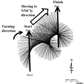
旋回運動に伴う船体の移動を視覚化するため,各スラスタ ーの使用状態での定常旋回状態での船首方位000°~000°ま での1旋回分の船体の動きをFigs.3~10に示した。旋回中 の回転中心位置は,全てのスラスター使用状態で船体の中心 位置に近かった。両スラスターを同時に使用すると北北東方 向へと移動していた(Figs.3-6)。一方,船首と船尾のス ラスターのどちらか一方を作動させた場合には,船体が西側 に向かって回頭するときよりも東側に向かって回頭するとき の方がより東方向に引き延ばされたような形状の軌跡となっ
た(Figs.7-10)。これらの軌跡はスラスターの水流吐出方 向(Fig.11)と実験時の風向が影響していると考えられる。
すなわち,計測時の風向は西南西方向で風速は8ノット(風 力3)であり,両スラスターを使用した場合には船体はこの 風のため北北東方向への移動が顕著になったと考えられる。
一方,BowとSternのスラスターのどちらかのみを作動させ た場合では,スラスターによる推力が船を回頭させる以外 に,水流吐出方向と反対方向に横移動させたと考えられた。
このため,片方のスラスターのみを使用すると西寄りの風が 強いため水流吐出方向が西方向になると風の外力が加わるこ とにより船体の東側への横移動量が増加したものと考えられ る。
Fig. 3 Tuning motion per second of the hull during 360 ° left side turning by using both thrusters with propeller pitch both 10° (referred as “ Both-P10° ” in the text)
Fig. 5 Tuning motion per second of the hull during 360 ° left side turning by using both thrusters with propeller pitch both 15° (referred as “ Both-P15° ” in the text)
Fig. 4 Tuning motion per second of the hull during 360 ° right side turning by using both thrusters with propeller pitch both 10° (referred as “ Both-S10° ” in the text)
Fig. 6 Tuning motion per second of the hull during 360 ° right side turning by using both thrusters with propeller pitch both 15° (referred as “ Both-S15° ” in the text)
Fig. 7 Tuning motion per second of the hull during 360 ° left side turning by using bow thruster with propeller pitch both 15° (referred as “ Bow-P15° ” in the text)
Fig. 9 Tuning motion per second of the hull during 360 ° left side turning by using stern thruster with propeller pitch both 15° (referred as “ Stern-P15° ” in the text)
Fig.11 Relationships between direction of turning and discharge flow by thrusters. Allows indicate direction of discharge flow.
Fig. 8 Tuning motion per second of the hull during 360°
left side turning by using bow thruster with propeller pitch both 15° (referred as “ Bow-S15° ” in the text)
Fig.10 Tuning motion per second of the hull during 360 ° right side turning by using stern thruster with propeller pitch both 15° (referred as “ Stern-S15° ” in the text)
移動量
各スラスターの使用状態における船首方位000°~000°ま での1旋回分の開始点から旋回終了点までの移動量をFig.12 に示した。Both-P及びSで旋回を行った場合,プロペラ翼角
Fig.12 Moving distances under various conditions Start
Bow
Stern
Finish Turning
direction
Bow
Stern Ship Moved to SE’ly direction
(mile) N
Stern
Finish Turning
direction
Moving to SE’ly direction
Bow
Stern Start
Bow
(mile) N
Start Bow
Stern
Finish
Turning direction
Bow
Stern Ship Moved
to ENE’ly direction
(mile) N
Start Bow
Stern
(mile) Finish
Moving to ENE’ly direction
Bow
Stern Turning direction
N
Using bow thruster
Using stern thruster
Using both thrusters
Both-P15㫦and Both-P10㫦 Both-S15㫦and Both-S10㫦
Stern-P15㫦 Stern-S15㫦
Bow-P15㫦 Bow-S15㫦
P10㫦 S10㫦 P15㫦 S15㫦 P15㫦 S15㫦 P15㫦 S15㫦
Both Bow Stern
により,約30~55mであった(Fig.12)。一方,Bow-Pと S,及びStern-PとSの旋回では53m~87mとなり,両スラス ターを同時に使用したときと比較するとその移動量は大きか った ( Fig.12 )。 移 動 量 の 最 小 はBoth-S15°の と き で約 30m,そして最大はStern-P15°のときで約90mとおよそ3倍 であった(Fig.12)。こうした船体の旋回に伴う移動をより 詳細に明らかにするためには,今後,各スラスターの推力と 風などの外力に対する船体の運動について力学的な検討を行 う必要があろう。
旋回角速度
各スラスターの使用状態での定常旋回時の平均旋回角速度
(Degree/Second)をFig.13に,1旋回に要した時間(s)を Table2に示した。旋回開始から定常旋回状態となるまでに 要する時間は,各スラスターの使用状態で異なり150~300秒 程度であった。例えば,Bow-P15°ではおよそ200秒程度で 定常旋回状態となった(Fig.14)。Both-P及びSのどちらか を使用するとプロペラ翼角に関わらず150~200秒程度で定常 旋回状態に達した。しかし,Bow-P及びSは200~300秒前後 かかり,Stern-P及びSでは,はっきりと定常旋回状態に達 したかは不明であった。一方,Stern-P及びSでは定常旋回 状態に達したかは不明であったが,旋回中の平均旋回角速度 はBoth-P15°及びS15°の約1/2程度と小さかった(Fig.13)。
また,Both-P10°とBoth-S10°の旋回角速度は,Bow-P15°
とBow-S15°の時とほぼ同じであった(Fig.13)。これは,
Sternスラスターの推力がBowスラスターの推力と比較して
Fig.13 Mean turning rates (Deg./Sec.) during turning under various setting conditions
Table 2 Time required for a turning with thrusters under various conditions
Fig.14 Example for mean of turning rate in the course of the trial “Bow-P15°”
小さいためだと考えられる。後部スラスターのみで旋回を行 うことは,明らかに他の旋回に比べて不向きであろう。
まとめ
本研究では,長崎丸において,船首と船尾のスラスターを さまざまに作動させ,DGPSの軌跡から船体の挙動を視覚化 することにより,回頭性能の把握と操船者へ操船の目安とな る情報の提供を目的とした。その結果,BowもしくはStern スラスターのみを使用すると旋回方向の違いで移動量に大き な差が生じること,両スラスターを使用すると短い時間で旋 回し移動量も小さくなることがわかった。スラスターは出入 港時や海洋観測時に多く利用される。特に出入港時は着岸岸 壁と対岸までとの距離が200~300m程度という港は少なくな い。こうした狭い港では,旋回に要する移動量は小さい方が 望ましいことから,両スラスターの同時利用が安全上望まし いと考えられた。また,海洋観測の場面でも同様であろう。
さらに,長崎丸くらいの規模の船舶では,スラスター室と乗 組員居住区とを大きく隔離することは物理的に困難である。
スラスターの稼働に伴う船内騒音や振動は,スラスターの翼 角が大きくなるのに伴い大きくなる傾向にある。この点から も片方のみのスラスターを大きな翼角で使用するのではな く,両スラスターを使用し小さな翼角で利用することが望ま しい。今回の結果でも操船への一助になるデータは収集でき たと考えられるが,船体挙動に関するさらなる計測を行うこ とが必要である。
要 旨
近年,船舶に搭載されているDGPSなどの船位測定機器の 性能は技術の進歩により測位・計測精度が格段に向上してい る。この精度向上に伴い船舶は,緻密な操船が求められてい る。本研究は,長崎大学水産学部付属練習船「長崎丸」に装 備されているスラスターを使用した時の船体の挙動を明らか にした。その結果,移動量は後部スラスターのみを利用した 時に最大となり,両スラスターを同時に使用した時と比べて Setting condition Time (Sec.)
Both-P10 Both-S10 Both-P15 Both-S15 Bow-P15 Bow-S15 Stern-P15 Stern-S15
439 450 300 293 423 435 557 561
P10㫦 S10㫦 P15㫦 S15㫦 P15㫦 S15㫦 P15㫦 S15㫦
Both Bow Stern
3倍程度大きくなった。旋回角速度は,後部スラスターを利 用した時に最少になり,前後スラスターを同時に使用した時 と比べ約半分になっていた。左旋回と右旋回では旋回角速度 に差はみられなかったものの移動量は異なり,風向きとスラ スターの水流の吐出方向との関連性が示唆された。これらの 知見は,操船者の操船技術の向上への一助となる。
謝 辞
本研究において,データの収集および解析に於きまして附 属練習船長崎丸の乗組員の方々には多大なご助力をいただき ました。ここに記して謝意を表します。
参考文献
1) 山中有一,松野保久:鹿児島大学水産学部紀要,39,
pp.13-19,1990.
2) 奥田邦晴:航海,94,pp.39-43,1987.
3) 矢田殖朗,高木保昌,兼原壽生,久野俊行,山路光徽,
西ノ首英之,古山裕喜:航海,96,pp.26-38,1987.