円弧翼の後流特性に基づくファン騒音のスペクトル解析
佐々木壮一
*
・林秀千人*
・佐藤大輔**
・奈須秀太朗**
Analysis of Fan Noise Spectrum Based onWake Characteristics of an Arc Blade
by
Souichi SASAKI * , Hidechito HAYASHI * , Daisuke SATOH ** and Shutaro NASU
In this study, the wake characteristics of an arc blade were measured by means of a wind tunnel experiment; the characteristics were defined as the width of the wake, diameter of the vortex, ratio of the vortex structure, and local lift. The influence of the angle of attack on the aerodynamic noise of the blade was quantitatively predicted by using these characteristics. It was experimentally clarified that the ratio of the vortex structure was closely associated with the noise characteristics at a certain angle of attack. The wake characteristics were applied to the prediction of the broadband noise generated from a multiblade fan; the fan noise-level distribution was estimated with high accuracy to be in the range from 1000–3000 Hz and was used to analyze the broadband noise of the fan. From the comparison of the fan noise level, it was found that the difference in the relative velocity caused by the biased internal flow was related to the noise levels.
Key words : Aerodynamic Noise, Wake, Vortex, Blade, Fan
1.はじめに
多翼ファンは人の生活に密 着した環境で使用され ることが多く,その騒音を低減することが送風機を開 発する上での課題となっている.羽根の入口角,出口 角およびその内外径比によって設計することが可能 な円弧翼は,多翼ファンの羽根車に用いられることが ある.この翼の設計形状はファンの空力特性だけでな く,その騒音特性にも影響を及ぼす.
Maruta
ら(1)
は,風洞実験で一様な流れの中に置かれた平板翼の後流とその翼から発生する空力騒音の関 係を研究した.その研究では,翼の迎え角が大きくな るとその離散周波数騒音が小さくなることが明らか にされている.このような騒音特性はファンの設計条 件と密接に関係するにもかかわらず,その騒音と迎え 角の理論的な関係については不明な点も多い.従って,
この空力騒音に関係する後流の基本特性を予め客観 的な方法で理論的に解析することは重要である.また,
翼の設計条件に基づくファン騒音の予測理論はこれ まで幾つか提案されているが
(2)(3)
,その予測式が翼の 後流特性のみで表された事例は少ない.本研究では,一様流中に設置された円弧翼の後流特 性が風洞実験によって測定され,その後流特性が多翼 ファンから発生する空力騒音の解析に応用されている.
翼の後流特性には,後流の幅,渦の直径,渦構造の比 および局所揚力が定義されている.円弧翼の空力騒音 に及ぼす迎え角の影響が,これらの後流特性を利用し て定量的に解析されている.さらに,これらの後流特 性を多翼ファンの広帯域騒音の予測へ応用した結果が 議論されている.
平成19年6月22日受理
* 機械システム工学講座(Department of Mechanical Systems Engineering)
** 生産科学研究科博士前期課程(Graduated Student, Graduated School of Science and Technology)
2.おもな記号
a 0
:音速(m/s)C L
:揚力係数D:後流の幅(m)
d:渦の直径(m)
L S
:スパン方向相関長さ(m)p:音圧(Pa)
p 0
:基準音圧(20μPa)r:音源から観測点までの距離(m)
S t
:ストロハル数U:主流速度(m/s)
u’:速度変動( m/s)
α:迎え角(°)
Γ:循環(m 2 /s)
ε:渦構造の比
κ:間欠率
λ:渦のアスペクト比
 ̄:自乗平均
3.実験装置および実験方法
図
1
は風洞実験に用いられた円弧翼の形状を示した ものである.その主要寸法が表1にまとめられている.この翼の二次元の形状は,後述の多翼ファンの翼のお よそ4倍である.
図
2
は風洞実験における流れと騒音の測定方法を示 したものである.一様な流れは一辺1 0 0 m m
の正方形 ノズルから噴出される.ノズル一辺を代表寸法とした レイノルズ数が約2 . 0
×1 05
のとき,測定部での主流 の乱れ度は0 . 2% 未満である.円弧翼は,その前縁が
ノズルの出口から1 0 0 m m
後方へ位置するように設置 されている.熱線プローブのサポートは,プログラム された座標データに基づいて,トラバース装置により 三成分の方向へ自動的に移動することができる.I 型 の熱線プローブで測定された後流の速度と速度変動は 熱線流速計で電圧信号へ変換され,その信号がA D
コ ンバーターを介して計算機へ入力される.空力騒音を 計測するための1/2
インチコンデンサマイクロホンは 主流と垂直方向に翼の後縁から1 . 0 m
離れた位置に設 置されている. 精密騒音計 で計測された騒音信号 はF F T
アナライザへ入力され,騒音の周波数特性がスペクトル解析される.
図
3
は多翼ファンの羽根車の外観写真を示したもの である.表2
にはそれらの主要寸法がまとめられてい る.この羽根車は前傾翼の遠心型に分類される.以下 の説明では,羽根枚数40
枚の羽根車による多翼ファンが
MF40, 120
枚のファンがMF120
と表記されている.図
4
には多翼ファンの内部流動と騒音の測定方法が 示されている.ファンの騒音は無響室で測定され,こTable 1 Main dimensions
C
t
ψ
R
32 mm Chord , C
100 ° Angle , ψ
2 mm Thickness , t
100 mm Span , b
20 mm Radius , R
32 mm Chord , C
100 ° Angle , ψ
2 mm Thickness , t
100 mm Span , b
20 mm Radius , R
Fig.1 Arc blade
0.1 m 1.0 m
Nozzle (□ 100mm) Arc Blade
Hot-Wire Anemometer
Traverse Machine
Hot Wire Probe Plenum
Box
Plenum Box
(a) Side view
(b) Top view
FFT Analyzer
Noise Level Meter
Fig.2 Experimental apparatus on wind tunnel
(a) MF40 (b) MF120
Fig.3 Impeller of multiblade fan
の無響室での暗騒音の
A
特性の全帯域騒音レベルは25dB
程度である.ファンの流量は,予め測定されたフ ァンのP-Q
特性の静圧に基づいて調整されている.騒 音の観測点は,送風機の回転軸上のベルマウス入口か ら1.0m
上流側の点である.騒音の測定では,モータ ーの回転数が2800rpm
に保たれている.ファンの内部 流動は,図4
に示される羽根車の外径より1 0 m m
外 側の位置で,5 孔球形ピトー管によって計測されてい る.羽根幅方向の測定位置として,前面シュラウドと 後面シュラウドの間を5 m m
間隔に分割した9
点が採 用されている.4.空力騒音の予測理論 4.1 円弧翼の後流特性
図
5
は一様な流れ場に設置された円弧翼の後流に形 成されるカルマン渦列とその圧力の関係を示したもの である.この研究では,渦の直径と後流の幅の比が一 つの後流特性として整理され,これが式(1)の渦構造の比と定義されている.
D d /
=
ε (1)
翼の後流にカルマン渦列が形成されるときには,その 後流の幅と渦の間隔は理論的に
D/L=0.2806
となる.従 って,1周期中の渦放出に伴う周期的変動現象の間欠 率κは式(2)として与えられる.ε κ = = 0 . 2806
D d L
D (2)
直径
d
の渦が図6
に示されるように速度変動u’で回
転するときには,その渦の循環は式(3)となる.) ( ' )
( t π d u t
Γ = (3)
後流中に渦が放出されるときには,翼の後縁近傍には この渦のポテンシャルによって局部的に上向きの揚力 が誘起される.このとき,一つの渦によって誘起され る局所的な揚力は,式(4)のマグナス効果によって見積 もられている.
Table 2 Main dimensions of the impeller
120 40
Number of blades , B
1 50 152.6
64.7 8 125 110 MF40
Thickness , t (mm)
MF120
Outer diameter , D 2 (mm) Chord length , C (mm) Inner diameter , D 1 (mm)
Span length , b 2 (mm) Inlet angle , β b1 (°) Outlet angle , β b2 (°)
Impeller
120 40
Number of blades , B
1 50 152.6
64.7 8 125 110 MF40
Thickness , t (mm)
MF120
Outer diameter , D 2 (mm) Chord length , C (mm) Inner diameter , D 1 (mm)
Span length , b 2 (mm) Inlet angle , β b1 (°) Outlet angle , β b2 (°)
Impeller
Microphone
Damper Chamber
Motor
Impeller Bellmouth
Static Pressure Tap 1.0 m
Scroll Casing D
2A
Fig.4 Experimental apparatus on the fan
-2.0 0 2.0 4.0 6.0
-1.0 0 1.0
x
p ( x ) L
-5.0 0 5.0 10.0
-1.0 0 1.0
p ( t ) T
t
D L
α
d (a)
(b)
Fig.5 Karman vortex street in the wake and the pressure fluctuation
SS PS
r d
Vortex of PS side d
u’
u’
Fig.6 Schematic diagram of local lift induced by vortex
L S
t U t
F ( ) = ρ Γ ( ) (4)
ここで,L
S
は渦のスパン方向相関長さである.このと き,渦の規模によって無次元化された局所的な揚力係 数は式(5)となる.U t u L
U d t t F
C
S L
) ( ' 2 2
) ) (
( 2 π
ρ
= κ
= (5)
この渦が後流へ角速度ωで周期的に放出されるとき,
この揚力係数の微分は式(6)によって与えられる.
D t C U t S
t C t
C t L
L
L 2 ( )
) ) (
( π
ω =
∂ =
∂ (6)
ここで
S t
はストロハル数である( St = f D / U ).
4.2 ファン騒音の予測
Curle (4)
はLighthill
の音響波動方程式(5)
に対して固体 表面の影響を考慮し,その解を式(7)として与えている.t t F r
r t a
p i i
∂
= ∂ ( )
4 ) 1
( 2
π 0 (7)
揚力係数の微分が式(7)の右辺に置き換えられると,渦 放出に伴う離散周波数騒音の音圧は式(8)となる.
r a
C D U
p S t L
0 3
4 λ
= ερ (8)
ここで, ̄は自乗平均を意味する記号,λは後流の幅 とスパン方向相関長さからなる渦のアスペクト比であ る.ここでは,スパン方向相関長さがカルマン渦列の 波長であると仮定し,そのアスペクト比が式(9)によっ て理論的に与えられている.
2806 . , 0
564 .
3 D
L S =
≅ Q
λ (9)
羽根車の後 流に形成 される カルマン渦 列の概 略 図 が図
7
に示されている.カルマン渦列の後流の幅が翼 後縁から近距離場でストロハル数を一定に保つように 拡散するときには,その後流の幅をn
個に離散化する ことができる.n f j
w D S
j t
j = 2 , = 2 〜 (10)
ここで, f は渦放出周波数,S
t
はストロハル数(S t =
0.2 ),w 2
は羽根車出口での相対速度である.羽根車の後流中にカルマン渦列が存在するときには,隣接する 翼の固体表面上に局所揚力が誘起される(Fig.7参照).
従って,多翼ファンの広帯域騒音は,式(8)の離散周波 数騒音を重畳することによって予測することができる.
n r j
a
C D w
p j ερ S t λ j L 〜
2 4 0 ,
3
2 =
= (11)
さらに,その音圧レベルのスペクトル密度は,式
(12)
によって見積もることができる.
= 2
0 2
log 10
10
p
L p j
p j (12)
ここで,p
0
は基準音圧である.5.結果および考察
図
8
は円弧翼の後流の速度と速度変動の等高線を示 したものである.翼の迎え角は10deg.である.図 8(a)
では,翼後縁近傍に死水領域が形成されている.図8(b)
では,強い速度変動の領域がその死水領域の正圧面側 と負圧面側で対称に形成されていることがわかる.以 下の解析では,速度変動が最も強い断面でその後流特 性が解析されている.図
9
はその断面での速度と速度変動の分布が示され ている.図9(a)において,その速度分布の半値幅が後
流の幅と定義されている.この後流の幅が代表寸法に 用いられると,ストロハル数が0.2
となることが実験 的に明らかにされている(6)
.一方,速度変動は渦放出 に伴ってその分布が形成される.このため,図9(b)の
速度変動の半値幅が渦の直径と定義されている(図5 参照).また,渦の回転速度は,その渦直径での速度変 動で規定されている.図
10
には迎え角と後流特性の関係が示されている.図
10(a)では,後流の幅と渦の直径がその迎え角ととも
PS SS
D j x
F j
Fig.7 Karman vortex street in the wake of the impeller
に増加した.図
10(b)の場合,例えその迎え角が変更さ
れても,速度変動はある一定の値となった.図10(c)
では,迎え角が10°よりも大きくなると,渦構造の比
が小さくなることがわかる.図
11
は円弧翼の迎え角と離散周波数騒音の関係を 示したものである.○が実測値の騒音レベルであり,●が予測値の騒音レベルである.実測値の騒音には暗
騒音が含まれているために,予測値の騒音レベルには 暗騒音が加えられている.予測値の騒音レベルは実測 値の騒音レベルの傾向を定量的に表すことができた.
図
10
の後流特性と比較すると,渦構造の比が翼から発 生する騒音に影響を及ぼすことがわかる.これは,渦 放出周波数がその循環の強さよりも,その騒音レベル に影響を及ぼすことを示唆するものである.図
12
は羽根車出口での相対速度の分布を示したも のである.図12(a)の横軸のθは,図4の A
の位置をPS SS
-1.0 0.0 1.0
0.0 1.0 2.0 3.0 4.0
x/C
0 0.4 0.8 1.2
0.4 0.6 0.8 0.8 1.0
1.0
Dead Air Region
U
0= 29.8 m/s , α = 10 °
Fig. (a) Velocity
PS SS
-1.0 0.0 1.0
0.0 1.0 2.0 3.0 4.0
x/C
0 0.2 0.4
U
0= 29.8 m/s , α = 10 ° Section of
Higher-Velocity-fluctuation
Fig. (b) Velocity fluctuation
Fig.8 Contour of the velocity and the velocity fluctuation of the arc blade in the wake
0 0.5 1 1.5
-0.5 0 0.5
( u − u
min) / ( U
0− u
min)
y / C
D U
0= 29.8 m/s Re = 6.3×10
4α = 10 °
0 0.1 0.2 0.3 0.4 -0.5
0 0.5
u' / U
0y / C y
*= 0
U
0= 27.7 m/s R
e= 6.3 × 10
4α = 10 °
−
d / 2
Rotating Velocity
Fig. (a) Width of wake Fig. (b) Diameter of vortex
Fig.9 Analysis of the wake characteristics in the wake
0 0.5 1.0 1.5
D/C , d/C
U
0= 29.8 m/s Re = 6.3×10
4D / C d / C
(a)
0 10 20 30 40 50
0 0.2 0.4 0.6 0.8 1.0
ε = d / D
U
0= 29.8 m/s Re = 6.3×10
4(c)
α ° 0
0.1 0.2 0.3
u' / U 0
U
0= 29.8 m/s Re = 6.3×10
4Measurement u' / U
0= 0.14
(b)
Fig.10 Relation between the angle of attack and the wake characteristics
0 10 20 30 40 50 60
60 70 80 90
α ° L A dB
U
0= 29.8 m/s Re = 6.3×10
41/3 Oct. Band
A-weight
Back Ground Noise ( 68.3 dB ) Measurement
Prediction
Fig.11 Relation between the angle of attack and the
aerodynamic noise level
基準とした反時計回りの回転角度である.相対速度の 分布は,羽根車の周方向へ非一様になった.図
12(b)
のスパン方向の速度分布は,この速度が最大になる位 置で測定されている.図12(b)では,MF40
の後面側の 相対速度がMF120
よりも大きくなった.図
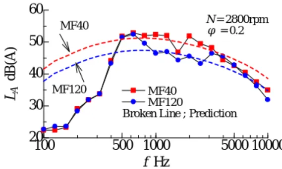
13
には,各ファン騒音のスペクトル分布が示され ている.図中の記号が実測値の騒音レベルであり,破 線がその予測値である.表3には,騒音の予測に用い られたパラメータが整理されている.予測値のファン 騒音のスペクトル分布(図中の破線)は,1000 から3000Hz
に分布するファン騒音のスペクトル分布を予測することができた.この周波数帯域の騒音レベルは 比較的高い.従って,被試験送風機の場合,この周波 数帯域の騒音レベルがファン騒音の支配的因子になる ことがわかる.一方,
1000Hz
よりも低周波側の騒音レ ベルが同程度であることから,この領域の騒音レベル は異なる流動現象によって発生するものであると考え られる.また,MF40の相対速度がMF120
よりも偏流 の影響で高速になるため,1000Hz
よりも高周波側でのMF40
の騒音レベルはMF120
よりも大きくなったと考 えられる.6.おわりに
この論文では,空力騒音の予測式が提案され,その 予測式に関係する後流特性が風洞実験で解析された.
この研究で提案された後流特性は,後流の幅,渦の直 径,渦構造の比および局所揚力である.さらに,これ らの後流特性を多翼ファンから発生する騒音のスペク トル解析に応用した結果,以下の結論が得られた.
(1)
後流の幅と渦の直径は円弧翼の迎え角とともに増 加した.一方,その局所揚力は一定であった.これら の後流特性は,定性的には空力騒音に及ぼす迎え角の 影響とは異なった.(2)
渦構造の比は迎え角10°からその角度とともに減
少した.この後流特性と離散周波数騒音の騒音レベル には定性的な関係が見られた.(3)
多翼ファンから発生する広帯域騒音はこれらの後 流特性を用いることで予測され,その後流特性に関係 するファン騒音は1000
から3000Hz
に分布することが わかった.(4)
異なる羽根枚数の多翼ファンの騒音レベルの比較 から,偏流した内部流動によって引き起こされる相対 速度の違いがその騒音レベルに関係することがわかっ た.100 150 200 250 300
0 0.2 0.4 0.6 0.8 1.0
θ ° w 2 / u 2
N = 2800rpm φ = 0.2 MF40 MF120
125 ° 260 °
Fig. (a) Circumferential direction
0.2 0.4 0.6 0.8 1.0
0.2 0.4 0.6 0.8 1.0
0 w 2 / u 2
z/b 2
φ = 0.2 N = 2800 rpm
Rear Side Front Side
MF40 MF120
Fig. (b) Span direction
Fig.12 Distribution of the relative velocity in the fan
100 500 1000 5000 10000
20 30 40 50 60
MF40 MF120
Broken Line ; Prediction
f Hz L A dB(A)
N = 2800rpm φ = 0.2 MF40
MF120
Fig.13 Spectrum distribution of the fan noise
Table 3 Summary of the wake characteristics and noise levels
0.140 Velocity Fluctuation , w
2’/w
20.685 Ratio of Vortex Scale , ε
54.4 58.3
Measured Noise Level , L
AdB
54.7 58.8
Predicted Noise Level , L
AdB
12.0 13.4
Relative Velocity , w
2m/s
MF120 MF40
0.140 Velocity Fluctuation , w
2’/w
20.685 Ratio of Vortex Scale , ε
54.4 58.3
Measured Noise Level , L
AdB
54.7 58.8
Predicted Noise Level , L
AdB
12.0 13.4
Relative Velocity , w
2m/s
MF120
MF40
参考文献