Articles
Computational Fluid Dynamics Analysis of the Optimal Shape for Side Holes in Indwelling Needles for Hemodialysis
Comparisons of analytical and experimental results obtained for each side hole shape
O
kuTomoko
1, S
himazakiNaoya
2, Y
amauchiShinobu
3, M
otohashiYuka
3, S
atoToshio
*and A
gishiTetsuzo
4(Received Date: March 13, 2019)
Key words: Indwelling needle, Computational fluid dynamics
I. Introduction
In recent years, blood purification therapy has consisted primarily of methods that focus on im- proving purification efficiency, such as long-du- ration dialysis, frequent dialysis, and online he- modiafiltration1). Ensuring an ample rate of blood removal during hemodialysis is an issue common to all of these forms of treatment, and it is also important to maintain purification efficiency.
In general, indwelling hemodialysis needles with an outer diameter of 15G to 17G are used in blood purification therapy2). Considering puncture pain and deterioration of vascular access during puncture, as well as hemostasis time, an indwell- ing needle with a narrow diameter is desirable3). With a narrow-diameter indwelling needle, how- ever, reports have described divergences between the set blood removal rate and the actual flow rate, and this divergence reduces purification efficien-
cy4). It is thought that providing side holes is an effective means of increasing the actual flow rate without changing the gauge or effective length of the indwelling needle. In reports on drainage catheters, the flow rate of the catheter is not pro- portional to the number of side holes, and the flow rate of catheters with side holes is said to be 13%
to 18% lower than of those without side holes5). The explanation for this is that the flow coming into the catheter through the side holes obstructs the flow through the hole at the tip. What we can presume from these reports is that, with indwell- ing needles as well, the design of side holes needs to take the flow from the tip into consideration, and that simply increasing the number of side holes may not increase the actual flow rate.
Providing side holes at the tip of the indwell- ing needle disperses the suction force acting on the hole at the tip and reduces the shear stress acting on the blood cells. Other advantages are that side holes at the tip can make it less likely that the in-
* Sato Toshio: Professor, Graduate School of Engineering; Faculty of Biomedical Engineering, Toin University of Yokohama. 1614, Kurogane-cho, Aoba-ku, Yokohama 225–8503, Japan
1 Oku Tomoko: Department of Medical Engineering, Graduate School of Engineering, Toin University of Yokohama
2 Shimazaki Naoya: Assistant professor, Faculty of Health Science, Gunma Paz University
3 Yamauchi Shinobu and Motohashi Yuka: Lecture, Faculty of Biomedical Engineering, Toin University of Yokohama
4 Agishi Tetsuzo: Faculty of Biomedical Engineering, Toin University of Yokohama
dwelling needle will adhere to the blood vessel wall, and side holes can also suppress increases in venous pressure, so that side holes can be consid- ered necessary at the tip of an indwelling needle with a narrow gauge.
With the aim of developing an indwelling nee- dle that has a small divergence between the set flow rate and the actual flow rate even at a narrow gauge, by changing aspects such as the number of side holes provided at the tip, as well as the shape and positioning of the holes, the authors used computational fluid dynamics (CFD) and conduct- ed a theoretical study on side holes in indwelling needles.
In a preceding study, the authors reported on the establishment of a CFD analysis method re- lating to blood removal properties of indwelling needles, and on the results of an analysis targeting the application of this method using commercially available indwelling needles. In the present study, the previously established method of analysis was used, and a CFD analysis was conducted, chang- ing the number and shape of the side holes in the analysis model of the indwelling needle. A proto- type needle with the same shape as the analysis model was also created, and the actual flow rate was measured to ascertain the usefulness of the CFD analysis.
II. Experimental method
1. Fabrication of the prototype indwelling needle It was difficult to create prototype indwell- ing needles with side holes of varying sizes and shapes using the same polypropylene from which commercially available indwelling needles are made. For the experiment described here, stainless steel pipe with an inner diameter of 1.3 mm and an outer diameter of 1.7 mm, which is the same size as the 16G indwelling needle, was used. Two types of needles that were the same as commer-
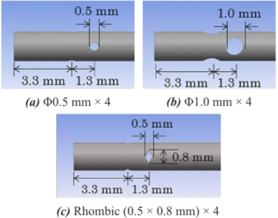
cially available needles were created: (1) indwell- ing needles without side holes, and (2) indwelling needles with four side holes in a round shape, with a diameter of 0.5 mm. In addition, two types of needles that were fabricated as newly proposed types were also created: (3) indwelling needles with four side holes in a round shape, with the diameter enlarged to 1.0 mm, and (4) indwelling needles with four side holes in a rhombic shape, with the lengths of the two sides being 0.8 mm and 0.5 mm.
First, the stainless steel pipe was cut to a length of 30 mm. The round side holes were drilled at the specified diameters using a drill. The rhombic side holes were made by first using the drill to make a hole and then using a wire-cutting machine and using electrospark machining to cre- ate rhombus-shaped holes. The tip of a very fine needle was then used to remove any burrs left in the side holes after they had been drilled, under microscopic inspection. The stainless steel pipe with the side holes in it is shown in Figure 1.
Fig. 1 Stainless steel pipe with side holes
Fig. 2 Prototype indwelling needle
Next, a 16G indwelling needle for hemodial- ysis made by Covidien Japan Inc. was taken, and the polypropylene outer cylinder needle was cut off, leaving only the adapter. The stainless steel pipe was inserted into the adapter and secured with adhesive to fabricate the prototype indwell- ing needle (Figure 2).
2. Method for measurement of actual flow rates and blood removal pressures
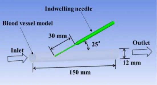
A vinyl chloride tube with an inner diameter of 12 mm was used as an artificial blood vessel, and a roller pump designed for an artificial heart-lung machine was used to circulate water at a tempera- ture of 25°C, with a flow velocity of 700 ml/min.
The indwelling needle was inserted into the artifi- cial blood vessel at an angle of 25 degrees, placing the needle so that the tip was positioned in the cen- ter of the artificial blood vessel. A T-shaped tube was then connected to the indwelling needle, and the arterial blood circuit and a digital manometer were then attached. The arterial line of the blood circuit was set on the roller pump of a monitoring apparatus for dialysis and connected to the blood circuit on the vein side with a connector.
After the indwelling needle and the all cir-
cuit had been filled with water, circulation was stopped, and the zero point of the digital manome- ter was calibrated with no water flowing. Next, the flow rate of the monitoring apparatus for dialysis was set in increments of 50 ml/min within a range of 50 to 500 ml/min, and the actual flow rate from the access on the vein side was measured for one minute at each flow rate setting, using a measuring cylinder. At the same time that the actual flow rate was measured, the blood removal pressure at the needle base end was measured at each of the set flow rates for 30 seconds at a sampling interval of 0.5 seconds. Both the actual flow rate and the blood removal pressure were measured 10 times at each set flow rate, and the mean values were cal- culated. Figure 3 shows the experiment system.
3. CFD analysis method
In the experiment described here, ANSYS CFX (Ver. 15, Cybernet Systems Co., Ltd. Japan) was used as the software for CFD analysis.
Figure 4 shows the CFD analysis model for an indwelling needle with an inner diameter of 1.3 mm, an outer diameter of 1.7 mm, an effective length of 30 mm, and no side holes. In the same way as for the experiment described in section 2-2, a model in which the indwelling needle was placed in an artificial blood vessel with an inner diameter of 12 mm, at an insertion angle of 25 de- grees, was used.
The analysis conditions were set to the same conditions as for the experiment: for the influx condition, water was set to flow into the artificial
Fig. 4 CFD analytical model Fig.3 Experiment system
blood vessel at a rate of 700 ml/min (density: 997 kg/m3, viscosity: 0.89 mPa·s, temperature: 25°C).
For the blood removal pressure, the value obtained in the experiment was set for the needle base end.
III. Experimental results
1. Results of actual flow rate measurements for the prototype indwelling needles and the commercially available indwelling needles (evaluation of the prototype indwelling needles)
For the prototype indwelling needles, stain- less steel pipe, which was different from the poly- propylene used for the commercially available indwelling needles, was used. Because of this, it was necessary to confirm whether the prototype indwelling needles had the same flow rate charac- teristics as the commercially available indwelling needles. For the indwelling needles, the stain-
less steel prototype indwelling needles and 16G polypropylene indwelling hemodialysis needles manufactured by Covidien Japan Inc. were used, and the indwelling needles without side holes and those with side holes were compared.
The measurement results are shown in Figure 5. For the flow rate characteristics, similar results were obtained with the stainless steel indwelling needles and the polypropylene indwelling needles.
Consequently, by conducting the experiment us- ing prototype indwelling needles made of stain- less steel pipe, it was possible to propose various shapes for the side holes.
2. Results of actual flow rates of the four types of prototype indwelling needles
The flow rate characteristics of prototype in- dwelling needles with varying side holes were confirmed. The results of actual flow rate mea- surements are shown in Figure 6. The actual flow rate decreased in the order of no side holes > side holes with a diameter of 1.0 mm > rhombic side holes > side holes with a diameter of 0.5 mm.
3. CFD analysis results
Table 1 shows the blood removal pressure and actual flow rate for the indwelling needle with no side holes, as well as the analysis-derived flow rates obtained by defining that blood removal pressure.
The results indicated that the analysis-derived (a) No side hole
Fig. 6 Results of actual flow rates of the four types of prototype indwelling needles
(b) Φ0.5 mm × 4 Fig. 5 Results of actual flow rates
flow rate exceeded the actual flow rate.
IV. Discussion
1. Calculation of fluid resistance
It was thought that the analysis-derived flow rate might have exceeded the actual flow rate be- cause of the effects of pressure loss that occurred in the blood circuit and roller pump that were not accounted for in the analysis model. To cite one example, when the set flow rate indicated in Table 1 was 200 ml/min, the blood removal pressure was -62.2 mmHg, and the actual flow rate was 203.9 ml. However, when this blood removal pressure of -62.2 mmHg was set, the analysis-derived flow rate was 218.4 ml, which was larger than the ac- tual flow rate. If the blood removal pressure in the analysis conditions was lowered, at a removal blood pressure of -55.3 mmHg, the analysis-de- rived flow rate was 203.9 ml, which is consistent with the actual flow rate. Consequently, it was found that, at a set flow rate of 200 ml/min, there is a pressure loss ΔP0 of 6.9 mmHg that is not ac- counted for in the CFD analysis. Using the above
method, it was possible to determine the pressure loss for each of the set flow rates. The pressure losses determined for each of the set flow rates are shown in Table 2.
In order to account for this pressure loss in the CFD analysis, a fluid resistance model was intro- duced at the needle base end. The fluid resistance S [Pa/m] in ANSYS CFX is defined using the fol- lowing equation:
... (1)
In order to set this as an analysis condition, it was necessary to determine the coefficient of permeability κperm and the pressure loss coefficient κloss.
If the length in the introduced fluid resistance model is set to L [m], the corrected pressure loss ΔP0 [Pa] can be determined from equation (1) us- ing the following equation:
... (2) The cross-sectional mean velocity v was cal- culated from the actual flow rate results for the indwelling needles without side holes. Figure 7 shows the approximation curve results determined Table 1 Blood removal pressure and actual flow rate
Set flow rate
[ml/min] 50 100 150 200 250 300 350 400 450 500
Removal pres-
sure [mmHg] -6.2 -19.0 -38.5 -62.2 -89.5 -125.4 -162.2 -196.7 -230.3 -259.2 Actual flow
rate [ml/min] 51.4 102.5 153.3 203.9 254.2 301.5 347.1 385.7 418.4 446.5 Analytical flow
rate [ml/min] 53.0 108.1 164.2 218.4 269.4 322.2 369.7 416.0 449.8 476.0 Table 2 The pressure losses determined for each of the set flow rates
Set flow rate
[ml/min] 50 100 150 200 250 300 350 400 450 500
Set pressure
[mmHg] -5.9 -17.4 -34.4 -55.3 -81.0 -111.1 -144.0 -174.5 -200.1 -224.8 Analytical flow
rate [ml/min] 51.3 102.5 153.2 203.9 254.3 301.4 347.2 385.7 418.3 446.4
ΔP [mmHg] 0.3 1.6 4.1 6.9 8.5 14.3 18.2 22.2 30.2 34.4
when v was plotted as the horizontal axis and ΔP as the vertical axis.
The approximation curve is expressed by equation (3).
... (3)
κperm and κloss are calculated by comparing the coefficients of v and v2 from equation (2) and equation (3).
The following values were substituted: L = 10 [mm], μ = 0.89 [mPa・s], ρ = 997 [kg/m3], and κperm
was determined to be 1.042×10⁻⁶ m2, while κloss
was determined to be 2.049 × 10³ m-1.
In order to account for the effects of the cal- culated pressure loss in the CFD analysis, a fluid resistance model with an inner diameter of 4 mm at the needle base end was provided (Figure 8).
The analysis conditions were the same as those for the experiment, and κperm and κloss were added.
Figure 9 shows the results of the actual flow rate and the analysis-derived flow rate. When a fluid resistance model was provided at the needle base end, the analysis-derived flow rate and the actual flow rate were consistent.
2. CFD analysis with fluid resistance added to models with side holes
Using the corrected blood removal pressure and fluid resistance, which was the analysis meth- od obtained using the indwelling needle with no side holes, CFD analysis was conducted on in- dwelling needles with side holes. For the CFD analysis models, the prototype indwelling needles (2), (3), and (4) were used. The shapes of the side holes in the models used for the CFD analysis are Fig. 7 The approximation curve results (Relationship
between v [m/s] and ΔP [Pa])
Fig. 8 CFD Analytical model with fluid resistance
Fig. 9 The results of the actual flow rate and the
analysis-derived flow rate Fig. 10 The shapes of the side holes (a) Φ0.5 mm × 4 (b) Φ1.0 mm × 4
(c) Rhombic (0.5 × 0.8 mm) × 4
shown in Figure 10.
The analysis results decreased in the order of no side holes > side holes with a diameter of 1.0 mm > rhombic side holes > side holes with a diameter of 0.5 mm. These results were highly consistent with the flow rates obtained in the ex- periment (Figure 11).
V. Conclusion
Based on the results of the experiment de- scribed here, it was possible to fabricate indwell- ing needles having the proposed side holes by machining stainless steel piping and to measure actual flow rates. With respect to CFD analysis, re- sults similar to the actual flow rates were obtained by adding fluid resistance, and an analysis method was successfully established.
In the future, we plan to create analysis mod- els of indwelling needles in which various design parameters relating to side holes have been further changed and conduct CFD analysis to propose the ideal shape for side holes in indwelling needles that will ensure the largest possible blood removal volume. If the side holes are too large, however, we believe that the mechanical strength of the indwelling needle will be lost, possibly causing fracturing of the needle inside the blood vessel in response to a very minor impact, and we intend to take parameters that could potentially cause prob-
lems in terms of practical application into account when proceeding with our investigation.
[References]
1) The Japanese society for dialysis therapy; https://docs.
jsdt.or.jp/overview/ (search and quote March 06, 2019) 2) Isabelle Chapdelaine, Camiel L. M. de Roji van Zujide- wjin, Ira M. Mostovaya, Renee Levesque, Andrew Dav- enport, Peter J. Blankestjin, Christoph Wanner, Menso J. Nube, Muriel P. C. Grooteman: Optimization of the convection volume in online post-dilution haemodiafil- tration: practical and technical Issues. Clinical Kidney Journal 2015; 8(2): pp. 191–198.
3) S. Osawa, H. Yamamoto, T. Saito, Y. Kohan, S. Kushi- ma: Study of penetration force of dialysis fistula needle (AVF needle), Kidney and dialysis, Separate volume Access 2004, pp.112–117.
4) Hitesh K. Metha, Diane Deabreu, James G. McDougall, Marc B. Goldstein: Correction of discrepancy between prescribed and actual blood flow rates in chronic hemo- dialysis patients with use of large gauge needles. Amer- ican Journal of Kidney Diseases; 39(6): pp.1231–1235.
5) J. Y. Park, C. Y. Park, B. G. Min: A numerical study on the effect of side hole number and arrangement in ve- nous cannulae. Journal of Biomechanics 2007; 40: pp.
1153–1157.
6) S. Yamauchi, Y. Motohashi, T. Sato, T. Agishi: Effects of side holes on blood removal characteristics based on measurement of the pressure distribution inside di- alysis punvture needles, Toin Research Bulletin No.34 (2016.6), pp.91–96.
7) N. Shimazaki, N. Nakane, S. Yamauchi, Y. Motohashi, T. Sato, T. Agishi: A study of the effects of side holes in indwelling needle for hemosialysis using computational fluid dynamics, Toin Research Bulletin No.36 (2017.6), pp.175–180.
Fig. 11 The results of the analytical flow rate