Dynamically Extensible Policy Server and Agent
Yasusi Kanada
IP Network Research Center, Research & Development Group, Hitachi, Ltd.
E-mail: [email protected] Abstract: This paper proposes a method, called the policy-
extension-by-policy method, for quickly and dynamically adding policy classes with new functionality to policy servers and agents.
In this method, users can add a new policy class to the policy server by using policy-definition (PD) policies, and they can define a method to translate a policy of the new class and to send to net- work nodes of different vendors through various types of device interfaces, such as CLI, MIBs, PIBs, APIs or hardware tables, by using policy-embedding (PE) policies. A PE policy also enables translating a policy of an existing class and sending the result to a new type of network node. PE policies contain command templates and methods for filling the templates. A program interpreter is embedded in policy agents to make flexible policy-to-configuration translation possible. A prototype system and example policies, i.e., access control, Diffserv, and VPN policies, were developed.
Keywords: Policy-based networking, Open programmable Net- working, Extensible language, Macro processor.
1. Introduction
In computer networks, a network node function can be extended by adding or replacing software or hardware of the node. Software can be added or replaced by code injection by using active packets (or “capsules”) [Ale 98] or API [Bis 98], e.g., sending Java byte- code, and hardware can be added or replaced by inserting/replacing a network node or a board in a node with a new function. Both software and hardware may be added or replaced dynamically while the node is running. If the network is controlled/managed by policies and the network function is added or replaced, new classes of policies (new types of policy actions) must be added. Because a function can be dynamically added, the corresponding policy class also has to be added dynamically.
However, conventional policy-based systems do not allow dy- namic extension. For example, COPS-PR (Common Open Policy Service for PRovisioning) [Cha 01] is a widely-accepted IETF standard protocol for policy provisioning. Policies with a specific range of functionality can be stored in a PIB (policy information base) in this framework. Thus, if COPS-PR is used, a new PIB must be developed in order to add a novel function. If a standard- based approach is taken, the vendor has to wait for standardization of the new or modified PIB. Vendors can add novel functions more easily if they use a private PIB, but they still need some time to develop the PIB, so a function cannot be added dynamically.
To add new classes of policies (i.e., to add novel functions) rapidly by using current technologies, plug-in architectures are good candidates. A C++ plug-in can be dynamically linked to the network node software, or a Java plug-in can be dynamically in- jected into the network node. However, plugging-in a general- purpose code is not very safe and most network nodes do not allow this type of extension. It is also a laborious task to define policies by using a general-purpose language.
To solve these problems, we have developed a method called the policy-extension-by-policy (PXP) method, for adding new policy classes. In this method, a new policy class is defined by using policy definition and embedding (PD/PE) policy rules. A PD policy rule contains a device-independent policy definition, and a PE policy rule contains a device-dependent method for translation of policies into device configurations.
2. Outline of the PXP Method
Dynamically extensible policies can be applied to both provision- ing and on-demand policies. Provisioning policies allow the net- work operators to deploy QoS or other policies according to their usage predictions, and on-demand policies allow the network users or applications to request bandwidth or other network resources just before they use the network. Both types of policies can be handled by using the PXP method. However, for simplicity, only provisioning policies are explained in this paper.
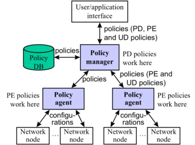
This system architecture for the PXP method consists of the
following software components (Figure 1): User interface (UI), Policy manager (PM), Policy database (DB), and Policy agents (PAs). All these components can be in a workstation or PC, or each component can be in a separate box. Especially, PAs can be embedded in network nodes. As a usual policy system, users, e.g., an administrator or operators, can input and edit policies using this system architecture, and can deploy them onto network nodes through the UI. The UI can send the policies and deployment commands to the PM, and can retrieve previously inputted policies from the PM. The PM can store the policies in the DB and retrieve them from the DB. The PM can deploy policies onto or undeploy policies from network nodes through PAs. Standardized interfaces can be used between these components. For example, LDAP can be used between PM and DB; COPS-PR can be used between the PM (PDP) and PAs (PEPs). However, the data formats, e.g., PIBs for COPS-PR, must be extensible.
Initially, at least the following policies exist: policy definition (PD) policies and policy embedding (PE) policies. Figure 2 illus- trates these policies and their relationship to user-defined policies.
A user or an application describes PD and PE policies. PD poli- cies define all user-defined (UD) policy classes; i.e., PD policies work as meta policies. Each PD policy rule defines a user-defined policy class, e.g., a QoS or a VPN policy class. Each PD policy rule introduces a novel management function into the PM. PE policies must define the method for translating the device- independent user-defined policies into device-dependent network node configurations. They introduce a novel management function into existing network nodes or they translate an existing policy for a new type of node. The PM may only know PD and PE policy classes, and PAs may only know PE policy classes; they initially might not know other classes of policies. These policies are to be defined and embedded by using PD and PE policy rules.
To define and to embed user-defined policy classes (i.e., QoS, etc.), the network administrator must input a PD policy that con- tains the definition of the user-defined policy classes, i.e., PD pol- icy rules; and must also input a PE policy that contains the translation method of the user-defined policy classes, i.e., PE pol- icy rules. The PD policy is deployed onto the policy manager it- self, so it will neither be distributed to policy agents nor network nodes.1 The PE policy is deployed onto the policy agents but it will not be distributed to network nodes.
The deployed PD policy in the PM takes effects when the user inputs or edits a user-defined policy (instance). The PM checks the validity of the user-defined policy using the information contained in the PD policy. The syntax and semantics of the user-defined
1 However, instead of deploying PD policies to the PM, they can be de- ployed onto PAs and the PAs can test the validity of the PD policies. This
User/application interface
Policy manager
Policy agent Policy
DB
Network node
Policy agent
Network
node Network
node Network
… … node
configu-
rations configu-
rations policies (PE and
UD policies) policies
policies
policies (PD, PE and UD policies) PD policies work here
PE policies work here PE policies
work here
Figure 1. A dynamically extensible policy system architecture
policy are checked, and error reports are returned to the UI if it contains errors.1 User-defined policies should be device- independent. So the information for the validity check (i.e., syntax and semantics descriptions) are usually also device-independent.
PD policies are, thus, also device-independent.
The deployed PE policy in a PA works when the PM installs the user-defined policy through the PA. The PA translates the user- defined policy into device-dependent configurations, e.g., a se- quence of commands by using the information contained in the PE policy. PAs for different devices translate a user-defined policy into different configurations. The node may be configured by us- ing a CLI (command-line interface), MIBs, PIBs, APIs, or hard- ware tables, so there may have to be two or more classes of PE policies that contain a rule corresponding to a PD policy rule (i.e., corresponding to a user-defined policy). A PE policy class is thus dependent on the configuration method and/or the device.
Policy translation methods can be described in PE policies in many ways. However, the following two means are used here:
command template and template fillers. A command template is a pattern. A command is generated from the pattern by filling the unfinished portions by using template fillers. For example, if the node interface is a CLI, the following template, which contains only one pattern, and four fillers can be used.
Template: access-list %s permit %s %s %s.
Fillers: N + 1, protocol || 'ip', source_address || 'any', destination_address || 'any'.
Here, “%s” in the template shows a place to be filled by a filler.
N, protocol, source_address and destination_address are variables, and 'ip' and 'any' are literals. Variables protocol, source_address, and destination_address can be specified in the condition part of user-defined policy rules. N is a work vari- able of the PA. If the value of N is 2, if protocol is 'tcp', and if source_address is 192.168.1.1 (but no destination_address is specified in the rule), then the following command is generated.
access-list 3 permit tcp 192.168.1.1 any
Filler “x || y” means that, if variable (or expression) x is valued (i.e., has a defined value) then the result is its value, but if x is not valued then the result is the value of y.
If the interface between a PA and nodes is different from a CLI, e.g., a MIB, hardware table, etc.; the syntax of template and fillers must be different. However, the same framework, i.e., the tem- plate-and-fillers framework, can be used.
A program interpreter is built into each PA and used for evalu- ating fillers. If the task of a filler is only to fetch a policy condition or action parameter value (e.g., source_address or scheduling_- priority) and to fill the template with the value, there is no elabo- rate algorithm required in PAs. However, if an expression such as
“N+1” is specified, this expression must be interpreted. An inter- method is used in the prototype system. (See Section 3.)
1 Instead of deploying the PD policy onto the PM, where the PM checks the validity, the policy can be deployed onto the UI, which can check the validity and return a more rapid response to the user.
preter is thus required. This interpreter is unnecessary if the ex- pression is compiled before sending it to a PA. However, if no native code can be dynamically linked to the PA and/or the inter- face between the PM and the PA is not suitable for sending a pro- gram, i.e., the only available interfaces are a CLI, MIBs, PIBs, or high-level APIs such as Java APIs (which no native code can be sent through), the interpreter is required. It enables policy exten- sion through preexisting device interfaces.
3. Prototype System
3.1 Outline
The author has developed a PXP-based prototype of a dynamically extensible policy system called DEPS. His purpose was not to develop a system that can be used in a real network but to develop a system for testing and refining the ideas about the extensible policy system architecture and methods. Three classes of PD/PE policies are predefined.
The components of DEPS are a UI, a PM, a DB, and PAs. The UI, PM, and PAs are implemented by Perl scripts. The UI is im- plemented by using a common gateway interface (CGI), a conven- tional Web technology. The DB is implemented by using a GNU Database Manager (GDBM). There are currently two types of PAs: the Hitachi router agent and the Cisco router agent. These PAs generate CLI commands.
3.2 Basic policy information-model
The grammar of the policies in DEPS follows the policy core in- formation-model extension (PCIMe) [Moo 01] developed by the IETF Policy Framework WG. In PCIMe, a policy rule consists of conditions and actions, and each condition or action contains variable-value pairs. Our model is a subset of PCIMe. For exam- ple, a rule that marks DSCP to a flow can be described as follows.2
if (source_address = 192.168.1.1 &&
protocol = 'tcp') { DSCP = 46 }
Here, source_address, protocol, and DSCP are policy vari- ables, and 192.168.1.1, 'tcp', and 46 are their values. Struc- tured values such as address range or list can also be used:
source_address = [192.168.1.1 ... 192.168.1.30], source_address = [192.168.1.1, 192.168.1.3].
Values have types; e.g., the type of 192.168.1.1 is IP address, that of 46 is integer, that of [192.168.1.1 ...
192.168.1.30] is IP address range, and so on.
A policy is a list of policy rules. Each policy belongs to a pol- icy class. The policy class name must be specified in each policy (instance). This means that a policy may not contain two or more different types of rules, i.e., all the rules in a policy must have the same type of functionality. For example, if a policy class is de- fined to have access-control functions, a policy of this class may not contain a rule that modifies the packet content. The translation method described in Section 3.3.2.3 demands this constraint.
2 The syntax used in this paper is different from that used in DEPS. Poli- cies can be inputted to DEPS by the GUI or by the Perl data syntax.
UD policy classes
QoS policy class
VPN policy class
…
… UD rule 11
…
UD rule 21 UD rule 22
…
QoS policy (UD policy 1)
VPN policy (UD policy 2) class-instance
relationship
PE policies for PA
class-instance relationship
deploy onto node
QoS commands (Command list 1)
…
PD policy for PM
Definition of QoS policy
class
Definition of VPN policy
class
… PD rule 1
PD rule 2
define
define
UD rule 21 UD rule 22
…
VPN policy (UD policy 3) class-
instance relationship
Translation method of VPN action
… PE rule 1
PE rule 2
Meta policy definition Policy definition
Meta policy deployment
Policy deployment
VPN commands (Command list 2)
VPN commands (Command list 3) UD rule 12 Translation method
of QoS action
User User
Network-node configurations
Figure 2. PD and PE policies and their relationship to UD policies
3.3 PD/PE policy design 3.3.1 Three policy classes
Three classes of PD/PE policies are predefined in DEPS: PolicyTo- Telnet, PolicyVariableDefinition, and PolicyValueTranslation.
User-defined policies are checked and translated in the following three steps (but not necessarily in this order).
1. Each variable-value pair is checked so an allowed type of value is assigned to the policy variable. A PolicyVariableDefinition policy rule is used for this purpose.
2. A value in each variable-value pair is checked and translated to a parameter value used in configuration commands. A Policy- ValueTranslation policy rule is used for this purpose.
3. A user-defined policy is translated to a sequence of commands by using a PolicyToTelnet policy rule. The translated command parameters are used here.
Each policy class is explained below.
3.3.2 PolicyToTelnet policy
PolicyToTelnet policy class, which is an amalgam of PD and PE policy classes, is the most important in DEPS. This policy is ap- plied when translating a user-defined policy. Each rule in this class of policy (instance) defines a user-defined policy class and the method of translating a policy of this class into telnet (CLI) commands. The abstract syntax of PolicyToTelnet policy rule is shown in Figure 3. This rule also consists of a condition and an action, which both consist of variable-value pairs.
3.3.2.1 Condition
The condition part of a PolicyToTelnet policy rule should contain only one variable-value pair on the policy class name: name and its value. (See the first line of Figure 3.) This name is used for se- lecting a rule from the PolicyToTelnet policy. This class of policy is applied when a user-defined policy is inputted to a PM or a PA.
The rule to be used is uniquely identified by using the policy class name specified in the user-defined policy.
3.3.2.2 Policy variable declarations
The variable-value pairs in the action part are classified as policy variable declarations, policy-prologue/epilogue translators, or pol- icy-rule translators. Each type of variable-value pairs are gathered
in Figure 3. However, the pairs can actually be de- scribed in an arbitrary order.
In part 1 (policy variable declaration), the value of the condition_variables variable is a list of pol- icy variable names that can appear in a condition of the user-defined policy. Options can be attached to each variable name. This allows the PM (or PA) to check the semantics of the user-defined policy rule conditions. The user cannot use any other policy variable names in rules of the user-defined policy.
The value of the action_variables variable is a list of policy variable names that can appear in an action of the user-defined policy. This allows the PM (or PA) to check the semantics of the user-defined policy rule actions. Options can be added too.
3.3.2.3 Outline of command generation
To explain the variable-value pairs in parts 2 and 3 in Figure 3, the process of command generation in DEPS is explained first. Fig- ure 4 shows the order of generating commands from a user-defined policy when deploying (or undeploying) it. First, the environment for this generation must be initialized by “Policy initialization”.
Next, a command list called prologue is generated. Then, com- mand lists that corresponds to rules are generated. “Rule initiali- zation” is done before generation of each command list for a rule.
Finally, the command list called epilogue is generated.
A prologue is not for a specific policy rule but for whole policy.
It may be required, for example, if the user-defined policy is a QoS packet queuing policy. In this case, the queues for all the queuing policy rules may have to be configured before generating the com- mands for the first rule. So the commands for queue configuration should be generated in the prologue. The commands to be gener- ated in a prologue depend on the type of the rule function. Thus, if rules that have different function types coexist in a policy, the prologue will be very complicated. This is the reason why the functionality of a policy is restricted by specifying a policy class.
An epilogue is for whole policy too. It may be required, for example, if the user-defined policy is an access-control policy. In this case, the access-control lists defined in the commands for each rule may have to be assigned to a network interface of the node after generating the commands for the last rule. This type of in- terface binding is required in Cisco routers. The commands to be generated in an epilogue also depends on the type of rule function.
3.3.2.4 Policy-rule translators
In part 3 (policy rule translators), the rule-command generation environment is initialized by using the value of the rule_- initialization variable. This policy variable contains work variable names of the PA and their initial values. The commands for installing a rule are generated by using the rule_deploy_- commands variable. This policy variable contains a template and fillers. They are organized in the form of “printf” in C; i.e., the first element of each value is the template, and the following ele- ments are fillers. An interpreter is required for evaluating the fill- ers such as “N+1”. A bytecode interpreter, which was function- ally much smaller than that of Java or Perl, was built into PAs.
A user-defined policy or policy rule is removed from the node when the user undeploys it. The commands for removing the configuration cannot be generated by using the template and fillers for policy deployment in general. Thus, ones for the rule, i.e., the values of the rule_undeploy_- commands variable, must also be specified in the rule.
3.3.2.5 Policy-prologue/epilogue translators
In part 2 (policy-prologue/epilogue translators), the method of generating prologue or epilogue is almost the same as that for policy rule translators.
The policy-command-generation environment is ini- tialized by using the value of the policy_initializa- tion variable. This policy variable contains work vari- able names of the PA (work_variable) and their initial values (initial_value) used in this command generation.
The prologue for a policy deployment is generated by using the policy_pre_deploy_commands variable.
This policy variable contains a template and fillers for the prologue. The epilogue is generated by using the pol- icy_post_deploy_commands variable. This policy
if (name = policy_class_name) {
# Action part 1: Policy variable declarations
condition_variables = {variable_name options, variable_name options, …}, action_variables = {variable_name options, variable_name options, …},
# Action part 2: Policy prologue/epilogue translators
policy_initialization = {work_variable = initial_value, …}, policy_pre_deploy_commands = [[template, filler, filler, …], …], policy_post_deploy_commands = [[template, filler, filler, …], …], policy_pre_undeploy_commands = [[template, filler, filler, …], …], policy_post_undeploy_commands = [[template, filler, filler, …], …],
# Action part 3: Policy rule translators
rule_initialization = {work_variable = policy_bytecode_program, …}, rule_deploy_commands = [[template, filler, filler, …], …],
rule_undeploy_commands = [[template, filler, filler, …], …] }
Figure 3. Abstract syntax of PolicyToTelnet policy
Generation order …
Prologue (generated from policy_pre_(un)deploy_commands)
Example: queue_size = 100, scheduling_algorithm = fair_queuing
Epilogue (generated from policy_post_(un)deploy_commands) Example: none (no epilogue)
Commands from the first rule (generated from rule_(un)deploy_commands) Example: bandwidth(first_queue) = 256 kbps
Commands from the second rule (generated from rule_(un)deploy_commands) Example: bandwidth(second_queue) = 128 kbps
…
Commands from the last rule (generated from rule_(un)deploy_commands) Example: bandwidth(last_queue) = 64 kbps
Policy initialization
Rule initialization Rule initialization
Rule initialization
Figure 4. Telnet command generation order in a PolicyToTelnet policy
variable also contains a template and fillers.
A prologue or epilogue may be required when a policy is un- deployed. Templates and fillers in the prologue and epilogue for policy undeployment, i.e., the values of the policy_pre_unde- ploy_commands and policy_post_undeploy_commands variables, also have to be specified in the rule if necessary.
3.3.3 PolicyVariableDefinition policy
A PolicyVariableDefinition policy is a PD policy, which is device- independent. This class of policy specifies the syntax and the se- mantics of variables used in user-defined policies. Each rule in this class of policy defines the set of allowed value types for a con- dition (or an action) variable. For example, value types ip_port and ip_port_range are allowed for condition variable source_- port. An example of a rule in this class of policy is given as:
if (name = 'source_port') {
value_type = ['ip_port', 'ip_port_range'] }.
The condition of a PolicyVariableDefinition policy rule contains only one variable-value pair under the condition (or action) vari- able name: name and its value, i.e., 'source_port' in the above example. This name is used for selecting a rule from the policy.
The action contains a variable-value pair on the set of allowed value types: value_type and its value, i.e., a list of 'ip_port' and 'ip_port_range' in the above example. The value types (their syntax and semantics) are specified in a PolicyValue- Translation policy described in the next subsection.
3.3.4 PolicyValueTranslation policy
A PolicyValueTranslation policy is an amalgame of PD and PE policies. So it may contain device-independent rules and device- dependent rules, and there may be a device-independent Policy- ValueTranslation policy. This class of policy checks the syntax and/or range of a policy variable value and specifies the method for translating the value into a configuration-command parameter, i.e., specifies the semantics operationally. For example, an IP address range can be defined as a value type and its syntax is specified in a rule of this class of policy, and an IP address range can be speci- fied in a user-defined policy rule and its syntax can be checked.
The bytecode interpreter is used for this translation.
An example of a PolicyValueTranslation policy rule is given:
if (name = 'ip_address_range') { mapping = '_',
syntax = ['\d+\.\d+\.\d+\.\d+', '\d+\.\d+\.\d+\.\d+'] }
This rule specifies the method of translating an IP address range value in a user-defined policy into a command parameter. The syntax variable specifies the syntax of the address-range value that consists of two addresses by using regular expressions. The mapping variable specifies the bytecode program that translates the parameter into hyphen-connected form.
3.4 Router agents
The three types of PD/PE policies explained in Section 3.3 are predefined both in the Hitachi and the Cisco router agents, and no other policies are predefined. The PM stores the policies received from the UI into the DB and sends them to the PAs. In DEPS, the PM does not check the validity of the policies, but PAs do it in- stead.
Usually, if the network nodes have different types of interfaces and/or different command systems or control data formats, such as MIBs or PIBs, different agents are required. For example, the following two differences may exist.
• Differences of command handling: Most routers have a CLI.
However, the command prompt and the method of error han- dling in these interfaces vary. The communication method should be customized for each device type.
• Network-interface information: Different devices have different methods for obtaining interface information, such as interface names or media types. Such information is used for handling the policy targets and for policy installation/removal.
Thus, initially, two separate agents for Cisco routers and Hi- tachi routers were developed. However, the functions of these agents were found to be very close, and they could share 85% of the program (i.e., Perl code).
4. Experiments Using the DEPS Prototype
Preliminary experimental results are summarized here. Three sets of user-defined policy classes, i.e., an access-control policy class, two Diffserv policy classes, and two VPN policy classes, were described by using Perl syntax, and sample policies of these classes were deployed to two small networks. One network consisted of Hitachi GR2000-20H routers, and the other consists of Cisco 7204VXR routers. The same set of user-defined policy classes were described for both Hitachi and Cisco routers. The number of rules and lines of the user-defined policies are measured. The number of lines required for generating a user-defined policy rule was 43 to 120, and approximately one third of rules are shared among Cisco and Hitachi agents.
5. Related Work
It takes much time to develop node-management interfaces for new functionality by using conventional types of interface. Kato and Shiba [Kat 00] developed a method for adding a new policy-based management interface by using active-networking technology.
New PDPs can be introduced to nodes and packets, and new manageable functions can be introduced much easier by their method. Their method and the PXP method can be combined to develop a rapidly extensible policy system.
DEPS can be regarded as a type of macro processor [Bro 74]. It expands a “macro”, i.e., a policy, into a command list. Macros were widely-used in assembly languages in 1950s and ’60s, and are still used in languages such as C. Assembly language macros and “macros” in DEPS are similar because both generate certain types of command sequence. However, “macros” in DEPS are specialized for a rule-based policy language. Although assembly languages have become less popular, Lassila [Las 96] used one for embedded special-purpose processors, in which they were still useful. The retargetable macro language in Lassila’s method was machine-independent, similar to the policy language in DEPS.
However, Lassila did not intend to use the macro for extending the high-level interface, i.e., the macro language.
6. Conclusion
In the proposed PXP method, preexisting interface types for policy deployment, such as CLI, MIBs, PIBs, APIs or hardware tables, can be reused for policy extension. Moreover, policy classes with new functionality can be defined by users or upper-layer applica- tions much easier than conventional methods by using templates and fillers in a form similar to “printf” in C. The amount of text required for describing user-defined policies can be significantly reduced compared with conventional methods. Our future work includes refinement of the policy design in the prototype system, introduction of means for managing the policy dependence or to avoid policy conflicts, finding a concise and sufficient set of inter- preter functions, and quantitative evaluation of the prototype.
References
[Ale 98] Alexander, S., et al.: “The SwitchWare Activenetwork Architecture”, IEEE Network, Vol. 12, No. 3, pp. 29–36, IEEE, July 1998.
[Bis 98] Biswas, J., et al.: “The IEEE P1520 Standards Initiative for Programmable Network Interfaces”, IEEE Communications Magazine, Vol. 36, pp. 64–72, IEEE, October 1998.
[Bro 74] Brown, P. J.: “Macro Processors and Techniques for Portable Software”, John Wiley & Sons, 1974.
[Cha 01] Chan, K. H., et al.: “COPS Usage for Policy Provisioning (COPS-PR)”, RFC 3084, IETF, March 2001.
[Kat 00] Kato, K., and Shiba, S.: “Designing Policy Networking System Using Active Networks”, 2nd International Working Conference on Active Networks (IWAN 2000), Lecture Notes in Computer Science, No. 1942, pp. 316–325, Springer, 2000.
[Las 96] Lassila, E.: “A Macro Expansion Approach to Embedded Processor Code Generation”, Workshop on Interaction between Compilers and Computer Architectures (EUROMICRO ’96), pp. 136–142, IEEE Computer Society Press, February 1996.
[Moo 01]Moore, B., et al.: “Policy Core Information Model Ex- tensions”, draft-ietf-policy-pcim-ext-05.txt, Internet Draft, IETF, October 2001.