図学研究日本図学会 ISSN 0387-5512
日本図学会
宮崎 興二 01 巻頭言
太田 高志,藤堂 英樹,加納 徹
徐 弘毅,兼松 祥央,茂木 龍太,鶴田 直也,三上 浩司,近藤 邦雄
安福 健祐,榎本 拓朗,阿部 浩和
竹之内 和樹,福田 幸一
森岡 陽介 03
11
19
27
35
研究論文
3 D プリンターを利用した自画像の多色刷版画用版木の作成 研究論文
ロボットアニメにおける戦闘シーンのための構図設計支援システム 研究論文
建築空間における色彩と肌理が空間認識に及ぼす影響 研究資料
Monge の図法幾何学における 3 次元問題と平面幾何定理に関する考察 作品紹介
既存転用を前提とした賃貸共同住宅のリノベーション
-玉川ビル702号を例として-
鈴木 広隆 安福 健祐 他
37 40 48
報告
第18回図学国際会議報告 プログラム
セッション報告
山口 泰 67 報告
日本図学会50周年記念事業収支報告
兼松 祥央 70
リレーエッセイ
照明設計とストーリーテリング
73 総目次
第52巻4号 通巻159号
2018年(平成30年)
12月
第52巻4号通巻159号
巻頭言 M E S S A G E
宮崎 興二 Koji MIYAZAKI
四次元ウォーズ
それは今から半世紀も前の遠い昔のこと.1970年の第 1 回図学会開始早々の研究発 表は,某私大に新設された図学教室の助手だった私(29歳)の生まれて初めての学会 報告「 4 次元空間における 2 , 3 の作図問題」だった.それ以来,私は, 4 次元の図 と形の宇宙で, 4 次元のフォースを使った八方破れのかたちの戦いをしてきた.その
4 次元ウォーズのいくつかの場面を紹介する.
エピソード1
田舎育ちの私には,共同研究者を集める力はなく,学界に通用する理論武装を学ぶ 機会もなかった.したがって生き延びるためには何もかも自分で工夫せざるを得ず,
その結果自ら開拓したのが 4 次元の図を描くというフォースだった.それを武器に,
生まれて初めての演壇に立ったことになる.そのためもあって,開口一番,「本研究 はすべて自分で考えたもので,参考にした書物はなく教えを受けた先達もいません」
と堂々と言ったことを覚えている.
そのあと,30分の持ち時間を使い切って,ふと会場を見渡した.と,一番後方に,
図学の大御所で図学会の生みの親の一人として知れ渡っていた神戸大学の小高司郎教 授がおられることに気が付いた.感動した私は,とっさに,「今回の私の考え方は小 高先生のご研究などにも役立つと思います」というコメントを添えて発表を終え,演 壇を降りて自席に向かって歩き始めた.すると同時に小高教授も後ろの席を立って,
私に向かって歩いて来られた.そして通路の中ごろで顔と顔を合わせるや,「近く神 戸大の図学の専任講師の席ができるから来ないか」といわれたのである.
こうして私は神戸大学教養部に移ることになった.
エピソード2
神大では,しばしば, 3 次元から類推した 4 次元のかたちの創作を課題にした. 3 次元の多面体や曲面の正確な作図が必要なため図学の訓練になると思われたからであ る.
生まれた作品の一つが,正 6 角形の 4 次元版としての菱形12面体をベースにした 4 次元の雪の結晶だった.これは,当時のスペースシャトルが宇宙で作った雪の結晶と よく似ていた.つまり重力の影響の少ない宇宙では,重力に支配される 3 次元の地球 上より動く自由度が一つ増えて 4 次元のかたちが実際に見られることになる.
それを知った朝日新聞では,大々的に報道すべく,私のところへインタビューに来 たあと,日本最高峰の雪の結晶の専門家数人の意見を求めた.ところが全員から,そ んないかがわしい話を相手にしてはいけない,と叱られて掲載できず,私は変人奇人 の欄で紹介されることになった.そのとき,変人奇人の特技として描いた,手と足が 3 本ずつ,目と耳が 3 個ずつある 4 次元のテニスギャルの図は,1984年11月のある日 の夕刊の半頁を飾っている.
こういうイグノーベル賞級の研究が実って,私は京都大学教養部へ移ることになっ た.
エピソード3
そのころ,京大教養部の教職員の間には,あるひそひそ話が広まっていた.物理学
1
図学研究 第52巻 4 号(通巻159号)平成30年12月
巻頭言 M E S S A G E
専門でアメリカの某有名大学での研究生活から帰られたW教授がまもなくノーベル 賞を貰うだろうというのである.それを聞いた私は,廊下などで教授を見かけたと きは最敬礼するようになった.ところが人事報告などで私のことをそれとなく知っ ていたらしい教授は,どこの馬の骨ともわからない私が挨拶しても露骨にそっぽを 向くばかりであった.
そんなあるとき,ゲバ学生対策のため,全教官が 2 名ずつペアになって 1 時間交 代で門番をすることになった.ところがW教授にとって不幸なことには,人員配置 の都合上,私とペアを組むことになったのである.仕方がない.やがて決められた 時間がきて私は門番に立った.予想通り,教授は少し遅れてそっぽを向きながら やってきた.気の毒と思った私は,自分一人でできますからお帰り下さい,とペコ ペコしながら申し出た.と,教授はそれには耳を貸さず,そっぽを向きながら,突 如ポケットから 1 枚の紙を取り出した.そしてそれを私にちらちら見せながら,こ こに描いてある図は間違っているだろう,という.ありがたさのあまり身震いしな がら見てみると, 4 次元の立方体の正確で有名な図が,英文の中に描かれていた.
それで私は,恐る恐る,これは正しいです,と反論した.そのとたん,何やて,そ れなら直交 4 直線があるはずなのに,そんなもんどこにもないやないか,と恐ろし い声が返ってきた.それで,いや,あの,これは投影です,と消え入るような声を 返した.そのとたん,すべてを悟った教授は,そうか投影か,投影だったんか,と 天を仰ぎながら独り言を言うや,そんならあとは頼みます,とやさしくいい残して その場を去った.
あくる日,廊下を歩いていると,何と教授がはるか向こうから足早に近寄ってき て,どうもどうも,お元気ですか,という.投影という図学用語にはこんなにもの すごい力がある.
エピソード4
W教授には結局ノーベル賞は回ってこなかったが,京大ではどこを歩いても,
ノーベル賞いいかえればイギリスの科学雑誌ネイチャーの面影にぶつかる.
そんな中の2003年10月のある日のこと,近くにあった出たばかりのネイチャーの 表紙を見てびっくりした. 3 次元の正12面体の 4 次元版である正120胞体(120個の 正12面体で構成される 4 次元多面体)のCGが大きくデザインされていたのである.
説明によると,フランスの天文学者がNASAの観測値に従って厳密に作図した最新 の宇宙像であるという.ところがじつは私は,昔プラトンが言った正12面体状の宇 宙の未来版のかたちはまさに正120胞体に違いない,と考えて,その正120胞体の宇 宙像を,1981年 8 月の数学セミナーの表紙に使ってもらっていたのである.さっそ くネイチャーの編集部に数セミの表紙写真を添えて申し出たところ,絶対に来ない といわれていた返事がすぐ届いた.ネイチャーはまじめな雑誌だからプラトン風の ふざけた考え方は紹介できない,という.またまたイグノーベル賞を逃がした一瞬 であった.
こうして実話の 4 次元ウォーズは,空想映画にはできないほど,まだまだ続く.
みやざき こうじ
京都大学名誉教授.大阪大学工学博士.京 都工芸繊維大学工芸学部建築工芸学科卒.
編著書『高次元図形サイエンス』,『多角形 百科』,『多面体百科』など.
Abstract
In this study, an attempt was made to create a multicolor print based on a digital portrait photo. Inspired by the trend of taking a self-portrait (selfie) or using a purikura (print club) machine, and the “Cool Japan” movement, it is thought that it might be an entertaining experience to have one’s “ukiyo-e”-nized portrait. The idea is extended further to have a woodcut print because it would be more entertaining and educational to experience the printing process by oneself. Image processing techniques were employed for modifying a photo so that it had a flat-colored ukiyo-e-like expression. These pictures were further converted to produce the three-dimensional (3D) geometric data for printing the woodblocks by a 3D printer. One can print a multicolor woodcut print on paper using ink and these woodblocks by following the same production process as that for a real multicolored woodblock print. The feasibility of the idea was demonstrated by producing the woodblocks and using them to print a real multicolor print work.
Keywords: 3D Printer/Digital fabrication/Image Processing/Multi- color Woodcut Print
概要
本研究はデジタル画像から多色刷り版画を作成することを 試みたものである.セルフィーやプリクラなど自分自身の画 像を工夫して撮ることの流行とクールジャパンと呼ばれるよ うな日本文化への注目に触発されて,筆者らは自身の画像が 浮世絵風に変換されると面白いのではないかと考えた.ま た,実際に多色刷りの版画として紙に印刷することができれ ばさらに面白く教育的な体験を与えることができるのではな いかと考えた.実現にあたって,基となる写真を画像処理に より浮世絵風な画像に変換し,さらに色別に分解することに よって版木の 3 Dデータを用意した.これを 3 Dプリンター によって印刷して版木を作成することができる.作成した版 木を使って実際に多色刷りの作品を紙に印刷することができ たことから,こうしたアプローチが可能であることを確認す ることができた.
キーワード: 3 Dプリンター/デジタルファブリケーション
/画像処理/多色刷り版画
Takashi OHTA1, Hideki TODO2 and Toru KANO3 太田 高志1 藤堂 英樹2 加納 徹3
3Dプリンターを利用した自画像の多色刷版画用版木の作成
Production of Woodblocks for Multi-Color Printing of a Self-Portrait Using 3D Printer
●研究論文
1. Introduction
In recent years, many camera applications and puriku- ra (print club) machines equipped with fascinating image processing filters have been developed to beautify or to add various entertaining effects to portrait pictures. Si- multaneously, Japanese culture is gathering a broad at- tention. These trends have inspired the author’s interest in having one’s own portrait picture converted into a
“ukiyo-e”-nized expression. It would be more entertain- ing to print it on paper as a real multicolor woodcut print by following the same production process as ukiyo-e.
Ukiyo-e is well-known as a genre of traditional Japa- nese pictorial art form representing contemporary life and cultures, mainly of the Edo era of Japan. Especially, the works produced by woodcut printing called “nishi- ki-e” are widely recognized among different ukiyo-e forms, and their artistry has been highly appreciated worldwide. Nishiki-e realizes multicolored representation by using multiple woodblocks, each of which corre- sponds to a different color. Its production process is com- plicated and should be performed by a team of artisans with different kinds of expertise. The production of woodblocks and the printing of multicolor prints could provide an interesting and educational experience to any- one who is not familiar with the creation process of the art. However, it would be difficult to implement the exact process of the printing. Especially, great expertise is needed to carve the woodblocks by using chisels. It takes a long time to prepare all the woodblocks for the neces- sary colors even if one could manage it.
The use of digital fabrication technologies could help to follow the production process more casually without losing the core idea of the process. Digital fabrication is widely recognized as a valuable tool for transforming digital data into real objects. It would be possible to pro-
3
図学研究 第52巻 4 号(通巻159号)平成30年12月 3
dealing with ukiyo-e for educational purposes[9]. The present work also includes an educational aspect by at- tempting to let people experience the process of produc- tion of a multicolored woodcut print.
Digital fabrication and 3D printers are used not only for the production of manufacturing parts, but also for creating artistic works[9]. There have also been attempts to use a 3D printer for reproducing lost ancient artifacts.
Among these works are the restoration of ancient Japa- nese mirrors[10] and Greek vases[11]. The present attempt does not aim to reproduce an art work completely but is similar to these works in that it uses new digital fabrica- tion tools for an ancient art form.
3. Ukiyo-e Production Process
The production process of ukiyo-e woodcut prints (ni- shiki-e) is described in this section for clarifying the task.
There are several steps involved in producing a printed work, each of which is performed by an artisan of specif- ic expertise. Therefore, the entire production is accom- plished by a group of such artisans.
The entire production process is roughly divided into the following steps.
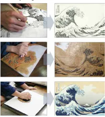
1. Drawing a sketch (Figure 1, top) 2. Engraving contour lines 3. Coloring
4. Engraving a woodblock for each color (Figure 1, middle)
5. Printing (Figure 1, bottom)
First, the painter draws an original drawing to be a base motif for the prints. Subsequently, a woodblock of outlines of the original paint is engraved by the engraver.
The painter fills the colors on the paper printed by that woodblock. Based on this colored painting, the engraver engraves multiple woodblocks, each of which is intended for printing a single color. Finally, the printer prints the work by spreading ink on the woodblocks and copying it by placing a paper on the block and rubbing it with a bar- en. The printing is repeated as many times as the number of colors used in the work. Therefore, special care is re- quired while placing paper on each block such that the accumulated colors are aligned properly in composing duce the woodblocks if one could prepare their 3D geo-
metric data and realize them by using a 3D printer. This was achieved by applying image processing techniques for converting an original portrait to a flat-colored pic- ture and then extracting the regions for each of the differ- ent-colored parts. One can obtain the 3D model of the woodblocks by means of the decomposed color regions.
The work mainly has two goals. The first is to examine whether producing a real multicolor woodblock print by using a 3D printer is feasible. The second is to demon- strate the use of a digital fabrication approach rather than constructing the parts for building an object. People use 3D printers for a variety of practical purposes, but they also can be used for creative works. The aim here is to present one such example.
2. Related Works
The computer graphics shading technique that renders a cartoonlike representation is called “toon-shading”[1]. The feature of toon-shading is the flattening of color gra- dation such that the subject appears to be painted in solid.
There have been attempts by using this technique to con- vert static images and videos into pictures to make them look as if they were hand-drawn[2–4].
There have been works that attempted to mimic a woodcut process by digital means in a virtual world[5,6]. Mizuno’s group applied this approach for archiving the woodblocks of existing ukiyo-e works by digitally re- trieving the geometric data from the printed works[7]. The group also elaborated on their research on image process- ing techniques for decomposing the colors of printed works[8]. While these works attempted to reflect the qual- ity of the printed works faithfully, the objective here is to convert a photo into a painted representation. The inputs to an image processing process in the aforementioned re- search were ukiyo-e works, which inherently possess the features of ukiyo-e representation. Therefore, the afore- mentioned approaches do not require a conversion pro- cess nor an analytical process. Such processes are neces- sary for our study but only simple methods are employed here for reducing and substituting colors yet. It is neces- sary to devise more-sophisticated conversion method in the future.
There has been an attempt to create interactive content
a digital photo. An image processing scheme is applied to flatten the colors of the photo and make it a picture to be printed. To produce a set of woodblocks, another im- age processing technique is used to decompose the pic- ture into separated images, each of which corresponds to a region of different color. The decomposed images are converted to 3D geometry data by adding a height attri- bute to the extracted region. The woodblocks are pro- duced from these geometry data by using a 3D printer.
The procedure for printing on paper is the same as the actual process, i.e., placing each color ink on the corre- sponding woodblock alternatively, and printing it on the same paper. The detailed procedures are described in the following sections.
4.1 Transformation of Portrait Picture
Instead of drawing a picture, a digital photo is used as an original source for creating woodblocks. Photos are taken in front of a monocolor screen for making the ap- plication of an image processing technique easier.
It was decided to flatten the colors of a photo and add distinct outlines, because these modifications were ex- pected to give the photo an ukiyo-e-like appearance. It is expected that such a conversion can be realized by apply- ing certain image processing functions: one for flattening the colors and the other for extracting the contour lines.
It is expected that deforming a person’s proportion can also contribute to adding a ukiyo-e look to a photo. The resulting pictures applying different deformation ratios are shown in Figure 3. The face size was magnified man- ually by a different magnitude in each picture. A defor- mation of a small ratio gave a good accent to the draw- ing, but the appearance became unappealing if the ratio becomes too large. This was not employed enough in this attempt, however. This effect should be pursued in future the original drawing.
All of these works are difficult in each way and require expertise. It is desirable to substitute the drawing and en- graving processes by digital means. The rest of the pro- cedures should be done manually because these are the very part that enables a person to appreciate what the multicolor printing task is like.
Figure 1: Production process of nishiki-e
(Courtesy of the Adachi Foundation for the Preservation of Woodcut Printing)
4. Production Process
There are three major steps in producing a multicolor print from an original digital photo, and they are repre- sented by the processes illustrated by different colors in Figure 2. These steps largely follow the processes per- formed for printing a nishiki-e described in the previous section.
Here, instead of drawing a sketch, the starting point is
Figure 2: Entire production process Figure 3: Effects of different magnification of the face size
5
図学研究 第52巻 4 号(通巻159号)平成30年12月
ors are used (Figure 4).
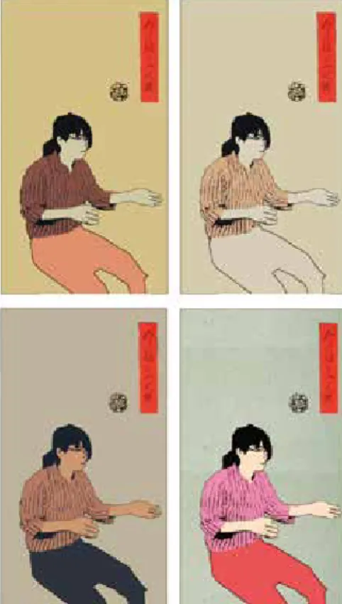
A color pallet was created for substituting the colors of the converted portrait picture. Thus, the converted picture was obtained after applying several image processing techniques. Figure 5 is an overview of the conversion process of a photo.
As for the final touch, a sign stamp was put onto the converted picture for mimicking nishiki-e works. An im- itation sign was prepared, and it was placed at an arbi- trary position (Figure 6).
4.2 Production of Woodblocks
To produce a woodblock using a 3D printer, the 3D geometric data for the blocks are needed. Furthermore, for realizing a multicolored woodcut print, there should be multiple woodblocks, because a different woodblock is needed for printing a different-colored region. It is easy to decompose a picture by colors because the pic- ture is already converted so that it is composed only by a few flat colors (Figure 7).
Each of the decomposed monocolor pictures was con- verted to a black-and-white bicolor image, and an identi- cal height to the black region was set to produce 3D geo- work.
The k-means smoothing method was used for reducing the colors. Reducing the colors results in eliminating the color gradation and realizes a flattened-color image. The parameters were set so that one could obtain a picture with four or five colors. Because it was necessary to pre- pare as many woodblocks as the used colors, the number had to be small for easing the preparation task. An at- tempt was also made to replace the colors of the original photo with those often used in real ukiyo-e works. This may also contribute to adding a ukiyo-e touch to a print.
The colors for substitution were obtained by performing a histogram analysis on these works, and the colors were selected in the order of the area size for which these col-
Figure 6: Pictures with stamps Figure 5: Portrait to ukiyo-e-like presentation
Figure 4: Extract colors from nishiki-e prints
Figure 8: Monochrome images and 3D geometry data Figure 7: Decomposing a picture into different color regions
To avoid the irregularity, one should also use an ap- propriate ink. Because the woodblocks produced by the 3D printer were made of plastic, and because plastic re- pulses water, it was slightly difficult to spread low-vis- cous ink on the surface uniformly. An attempt was made to use an oil ink for printing a woodcut print.
5. Discussion
In this work, an attempt was made to convert a por- trait photo to a ukiyo-e-nized picture and make it a real multicolor woodblock print. It is the author’s belief that the attempt was successful in demonstrating this is possi- ble. A set of woodblocks and purikura like stickers were produced from a self-portrait photo (Figure 11). It was also possible to produce a multicolor print on paper in the same way as by ukiyo-e production (Figure 12).
Figure 12: Variation of printed works Figure 11: Woodblock and purikura stickers
Although there was some success in producing wood- block prints, it was observed that there are other issues that should be pursued further for realizing the quality originally anticipated. First, because of the early stage in attempting this approach, only a simple image processing of smoothing colors was employed for converting an original photo to obtain an expression that has a ukiyo-e look. Only a simple assumption was made in defining the metric data (Figure 8). Woodblocks were obtained by
printing these data using a 3D printer.
4.3 Printing on Paper
Once the woodblocks were produced, they were used alternatively with different-colored ink on the same paper to obtain a multicolor print. After ink of a certain color was spread over a corresponding woodblock, a paper was placed on it, and a baren, which is a disk-shaped pad, was used to transfer the color to the paper (Figure 9).
Figure 9: Printing process on paper
In using the woodblocks produced by the 3D printer, it was observed that smoothing the surface of the block with fine sandpaper is required. Otherwise, ugly irregu- larity was observed in the printing. Figure 10 shows the difference between nonsmoothed and smoothed wood- block surfaces. The irregularity of spreading ink is ob- served in the nonsmoothed block (left image of Figure 10).
Figure 10: Difference between the surface conditions
7
図学研究 第52巻 4 号(通巻159号)平成30年12月
more precisely and would be more suitable for this pur- pose. We employed a 3D printer this time because it is the most convenient device for producing a real object from digital data, especially in terms of availability and usability. In terms of the quality of printing, the varia- tions in printing ink and paper may also influence the re- sults. Such aspects should also be examined in future study.
When considering the user experience in converting a picture from an original portrait, it is preferable not to re- quire many configurations on the parameters on the con- version. However, certain users would like to choose the colors and other options by themselves. It is necessary to examine the amount of controllability when systemizing this process.
6. Conclusion
Rendering one’s photo a ukiyo-e manner and produc- ing a woodblock print of that picture were considered.
One of the goals of this work was to examine whether creating a multicolor woodcut print from a digital photo is feasible, and a woodcut print was successfully created by producing the woodblocks using image processing techniques and a 3D printer. We consider that we were able to demonstrate an example of the use of digital fab- rication for an application other than practical fabrica- tion.
Because the study was in the early stage of this at- tempt, the focus was on the successful completion of the entire process, and we have not been able to pursue a good quality of the output. It was observed that there are issues for improving the quality, such as devising an im- age processing method for mimicking the style of uki- yo-e representation better.
The ukiyo-e look was sought as the motif in this work by considering that the experience of printing by follow- ing the traditional practice would be an educational and entertaining experience. However, because the whole process can be applied to pictures of any other design if they are flat-colored, it would be possible to produce printed works of a unique expression by employing a dif- ferent image processing effect. We would like to pursue a broader range of applications of the same approach in fu- ture.
features of ukiyo-e representation. We mainly considered a feature arising from woodcut prints i.e., the painted colors should be flattened. Other factors, such as deform- ing the representation, should be considered for making a portrait have the features of famous ukiyo-e works. We consider devising a more suitable image processing method that includes such a deformed representation.
The colors of the converted picture were replaced by those extracted from existing ukiyo-e works. Substitution of colors can be arbitrary, and a different selection of colors can produce variation in the output representations (Figure 13). It is also possible to use the combination of colors used for manga or animation characters. This would result in an interesting representation wherein the applied picture is reminiscent of the original work.
Because there were difficulties in printing on paper with ink, we feel a need to examine the suitability of ma- terials in printing the woodblocks. Wooden material can be used with a 3D printer. We anticipate that the use of wood material would facilitate spreading ink uniformly over the woodblock’s surface. The means of producing woodblocks should also be considered. A 3D printer was used for this purpose in this attempt. However, because the desired process is an engraving of wood, a computer numerical control router can imitate the original process
Figure 13: Variation of color combinations
Tech @MFA Boston, https://blog.adafruit.com/2016/07/06/
your-last-chance-to-catch-amazing-wearable-tech-mfa- boston-wearablewednesday/, last accessed June 10, 2017.
[11] Ancient Origins, The magic mirror of shaman Queen used in ancient Japanese rituals, http://www.ancient-origins.net/
news-history-archaeology/magic-mirror-shaman-queen-used- ancient-japanese-rituals-001291, last accessed June 10, 2017.
[12] Greek Reporter, 3D Printing Brings Replicas of Ancient Greek Art to the Classroom, http://usa.greekreporter.
com/2016/10/19/3d-printing-brings-replicas-of-ancient- greek-art-to-the-classroom/, last accessed Jun 10, 2017.
Acknowledgements
The authors thank to Ms. Misako Kobayashi of Joshibi University of Art and Design for her help in printing woodblock prints. The authors also thank to Mr. Wataru Noguchi, Ms. Ai Masuda and Mr. Kenji Muraoka, for- mer undergraduate students of Tokyo University of Tech- nology, for their contribution in carrying out the prelimi- nary studies.
References
[1] Gooch, A., Gooch, B., Shirley, P., and Cohen, E. A Non- Photorealistic Lighting Model for Automatic Technical Illustration, Proceedings of SIGGRAPH ’98, 447–452 (1998).
[2] DeCarlo, D. and Santella, A. Stylization and Abstraction of Photographs, Proceedings of ACM SIGGRAPH 2002, 769–
776 (2002).
[3] Lake, A., Marchall, C., Harris, M., and Blackstein, M.
Stylized Rendering Techniques For Scalable Real-Time 3D Animation, Proceedings of the 1st international symposium on Non-photorealistic animation and rendering (NPAR’00), 13–20 (2000).
[4] Winnenmöller, H., Olsen, S. C., and Gooch, B. Real-Time Video Abstraction, ACM Transactions on Graphics (TOG) - Proceedings of ACM SIGGRAPH 2006, 1221–1226 (2006).
[5] Mello, V. B., Jung, C. R., and Walter, M. Virtual Woodcuts from Images. In Proceedings of the 5th international conference on Computer graphics and interactive techniques in Australia and Southeast Asia (GRAPHITE ’07). 103–109 (2007).
[6] Mizuno, S., Okada, M., Toriwaki, J., and Yamamoto, S.
Improvement of the virtual printing scheme for synthesizing Ukiyo-e, Object recognition supported by user interaction for service robots, vol.3, 1043–1046 (2002).
[7] Okada, M., Mizuno, S., and Toriwaki, J. Digital Ukiyo-e Preserving Project: Intelligent Coding and Constructing Archives of Printing Blocks. in Proceedings of VSMM 2001, 209–217 (2001).
[8] Terai, T., Mizuno, S., and Okada, M. Color Decomposition of Overlapped Watercolors. in Proceedings of ICPR2004;
International Conference on Pattern Recognition, vol. 2, 919–
922 (2004).
[9] Tamaki, H., Sakai, T., Ota, Y., Egusa, R., Inagaki, S., Yamaguchi, E., Kusunoki, F., Namatame, M., Sugimoto, M., and Mizoguchi. H. Participatory Design of UKIYO-E Game for Children to Support Art Appreciation Based on Interacting with Pictures. In Proceedings of the 15th International Conference on Interaction Design and Children (IDC ‹16).
637–642 (2016).
[10] adafruit.com, Your Last Chance to Catch Amazing Wearable
●2018年 4 月15日受付
About the Authors
1. Takashi OHTA, Ph.D., is an associate professor at the School of Media Science, Tokyo University of Technology. He can be reached at: takashi@stf.
teu.ac.jp, 1404- 1 Katakura, Hachioji, Tokyo, Japan, 192-0982.
2. Hideki TODO, Ph.D., is an assistant professor at Chuo Gakuin University. He has focused on research and development of computer graphics techniques, including related image processing methods. His e-mail and postal address are as follows: [email protected], Chuo Gakuin University, Faculty of Liberal Arts, Room 708, Research bldg.,451, Kujike, Abiko, Chiba, Japan, 270-1196.
3. Toru KANO, Ph.D., is an assistant professor at the School of Media Science, Tokyo University of Technology. His e-mail address is: [email protected].
The postal address is the same with the author 1.
9
図学研究 第52巻 4 号(通巻159号)平成30年12月
Abstract
Japanese robot animation has a long history and many masterpieces have been produced. Robots in the anime have important roles for showing deep storytelling and unique drama. A
“battle scene” which visualize a combat against one or more opponents is one of the most important factors of modern robot anime. In this paper, we propose a support system for designing a camera blocking of a battle scene in the robot anime. We have extracted 2531 shots in battle scenes in 10 existing robot animation works and classified them by 17 items such as robot's action, camera movement and shot size. The users can browse classified scenes and their detailed information on camera work and camera blocking stored in our library system, and use desired one as a reference when they draw their original battle scene. Experimental results show that our system is useful for the user without production experience, and facilitates drawing a camera blocking of the battle scene.
Keywords: CG / Robot Animation / Battle scene design / Camera work and Composition
概要
日本のロボットアニメは長い歴史を持ち,多くの傑作が制 作されている.また,戦闘シーンはロボットアニメにとって 重要なシーンの 1 つである.本研究では,ロボットアニメ における戦闘シーン制作のための構図設計支援システムを提 案 する.そのため,既 存 のロボットアニメ10 作 品 から,
2531の戦闘シーンを抽出し,ロボットの行動,カメラの動き,
ショットサイズなどを分類した.また,これらの分類を用い てカメラワークや構図に関するデータのライブラリを開発し た.このライブラリを用いることで,ユーザーは戦闘シーン を制作する際に,演出意図に合わせたカメラワークを検索可 能である.開発したライブラリを用いた実験の結果,このラ イブラリは特に映像経験のないユーザーにとって有用である ことが分かった.このことから,ディレクターなど映像制作 ツールの取り扱いを専門としないユーザーでも容易に戦闘 シーンの構図設計が可能である.
キーワード:CG/ロボットアニメ/ 戦 闘 シーン/カメラ ワーク/構図
Hongyi XU1, Yoshihisa KANEMATSU2, Ryuta MOTEGI3, Naoya TSURUTA4, Koji MIKAMI5, Kunio KONDO6 徐 弘毅1 兼松 祥央2 茂木 龍太3 鶴田 直也4 三上 浩司5 近藤 邦雄6
ロボットアニメにおける戦闘シーンのための構図設計支援システム
A Support System for Designing Camera Blocking of Battle Scenes in Robot Anime
●研究論文
1. Introduction
Robot (mecha) anime which features robot in battle is one of the most popular genres in Japanese anime. The series of manned robot started in 1970s and many mas- terpieces gained great popularity around the world. In these robot anime, “battle scene” which usually features a fight against opponent robots is an important factor af- fecting the popularity of that anime. A battle scene is composed by large number of shots with complicated camera switching for producing the powerful actions of robots. Therefore, elaborate design based on the inten- sions of the director is necessary to build these scenes.
Previous research about camerawork and lighting tech- nique do not focus in camera blocking. Investigation about camera blocking is required for the battle scene which contains a lot of shots and special film transition such as wipe used to show a robot and its pilot at the same time.
The purpose of this study is to provide a support sys- tem for battle scene design. We extracted every battle scene and shot in 10 famous robot animation works.
Then extracted scenes and shots are classified based on the scene situation, the robot action, the information on camera work and composition. Finally, we build a sys- tem combined with a battle scenes library containing camera blocking that enables easy retrieval of the user desired scene by robot action.
2. Related Work
Kanematsu et al.[1] has analyzed existing 3D computer graphic animation works and proposed a retrieval system combined with a digital library of typical camera work and composition for the unit of shot. The shot stored in the library are tagged by the direction of camera move- ment, technical terms in cinematography such as pan and
3.2 Classification of Scene Information
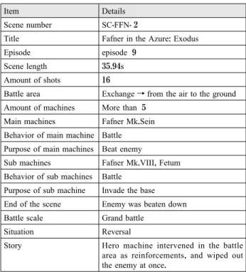
We created records consisting of the following 17 items for each extracted scene. Previous research on lighting technique[4] shows that using the keywords which describe the situation instead of technical terms in cinematography is helpful when the user searches the in- formation on directing. We achieve search without tech- nical terms by classifying the battle area, battle scale and the situation of the battle. Table 1 shows a record of the battle scene shown in Figure 1.
(1) Scene number (2) Title
(3) Episode (4) Scene length
(5) Amount of shots in this scene
(6) Battle area; the area where the battle takes place. We categorize areas into the ground, the air, the space and the indoors according to the robot anime which was chosen in this research. Furthermore, the battle area may change during one scene. For example, the battle area can be changed from the air to the ground.
In this case, we recorded it as “Exchange” within the details.
(7) Amount of machines (8) Main machines
(9) Behavior of main machines (10) Purpose of main machines (11) Sub machines
(12) Behavior of sub machines (13) Purpose of sub machines dolly, and other support information. Nakajima et al.[2]
extended the library using the match moving technique to numerically track the camera movement through a shot. These works convert animators’ tacit knowledge to explicit knowledge through classification of shots and making a digital library. Their proposed retrieval system enables users to find the desired shot and its directing in- formation and use them as a reference.
However, shot-by-shot analysis is not enough when considering the battle scene because one action may be composed of a sequence of shots. For example, the action of “shooting an opponent” can be divided into four shots;
“holding a gun”, “pulling the trigger”, “a bullet is fired”, and “the bullet hits the opponent”. Therefore, we made not only shot-by-shot analysis but scene-by-scene analy- sis. The information on camera blocking can be obtained from the result of scene-by-scene analysis.
3.Analysis of Existing Works
We analyzed 10 existing robot anime features manned robot with high sales such as “Mobile Suit Gundam SEED”, “Neon Genesis Evangelion” and “Fafner in the Azure: Exodus” to extract common directing techniques necessary to design the camera blocking of the battle scene. First, we extracted 73 battles scenes and made re- cords of scene information. Then, we analyzed 2531 shots extracted from battle scenes to obtain information on camera work. Both pieces of information are orga- nized and put into our battle scene library.
3.1 Extraction of Battle Scene
Based on Kaneko’s rule for scene transition[3], we de- fined the battle scenes as scenes contains robot’s attack- ing action. Switching of scenes occurs by jumping in time and shifting focus between characters.
With the above conditions, we have extracted the bat- tle scenes and made records of the scene information.
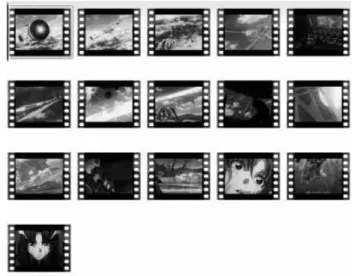
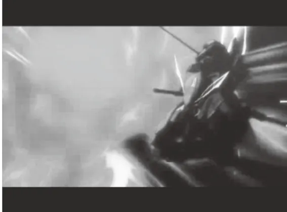
Figure 1 shows an example of a battle scene. The scene contains the information on battle areas, such as the ground or the air, the battle scale which indicates the magnitude of battle, battle situation, behavioral patterns of robots and characters, fighting abilities of robots and characters, and stories for showing what happened in this battle scene.
Figure 1. An example of a battle scene
©XEBECzwei, FAFNER EXODUS PROJECT, MBS
12 Journal of Graphic Science of Japan Vol. 52 No. 4 /Issue no. 159 December 2018
3.4 Classification of Shot Information
In this research, we focused on actions and poses of the characters, location of a battle scene in the shot and composition of shot with camera work. These three ele- ments are important for the shots constituting battle scene. Therefore, we created records consisting of the following 17 items for each extracted shot. Some items are classified into categories as the classification for scenes, so that the user can search using the keywords describes the situation to obtain a set of directing infor- mation.
(1) Shot number (2) Title (3) Shot length (4) Amount of robots
(5) Main object; a robot or a character the camera is fo- cusing on. We also defined his/her role in the story as the following six roles based on Kaneko’s defini- tion of character roles[5].
(a) Protagonist (b) Protagonist’s robot (c) Antagonist (d) Antagonist’s robot (e) Cooperator (f) Cooperator’s robot
(6) Action of main object; the action which robot or character are carrying out in a shot, classified into the following 11 actions.
(a) Standing (b) Move (c) Attack (d) Transform (e) Hutten (f) Evade (14) End of the scene
(15) Battle scale; magnitude of battle defined by the num- ber of robots participating in the battle scene, classi- fied into the following 4 types.
(a) 1 vs 1
(b) Limited battle; either of one party with 2-4 robots (c) Mass battle; either of one party with 4-9 robots (d) Grand battle; either of one party with over 10 ro-
bots
(16) Situation of the battle; the main object in the battle scene classified into the following 4 types.
(a) Superiority; when the main character has an advan- tage in the scene.
(b) Inferiority; when the main character has disadvan- tage in the scene.
(c) Rivalry; when the main character and enemy are in the equal situation.
(e) Reversal; when the advantage switches during the scene.
(17) Story; the detailed story of the battle scene.
Table 1. An example of a battle scene record
Item Details
Scene number SC-FFN- 2
Title Fafner in the Azure: Exodus
Episode episode 9
Scene length 35.94s
Amount of shots 16
Battle area Exchange→from the air to the ground Amount of machines More than 5
Main machines Fafner Mk.Sein Behavior of main machine Battle
Purpose of main machines Beat enemy
Sub machines Fafner Mk.VIII, Fetum Behavior of sub machines Battle
Purpose of sub machine Invade the base End of the scene Enemy was beaten down Battle scale Grand battle
Situation Reversal
Story Hero machine intervened in the battle area as reinforcements, and wiped out the enemy at once.
3.3 Shot Extraction from Battle Scene
In this paper, a shot is defined as a short sequence from the beginning of camera rotation path to the end of it. We divided the battle scene into a set of shots by using movie editing software (Figure 2).
Figure 2. Extraction process of shots
main object.
(b) Medium angle; when the camera has been set on the eye level of the main object.
(c) When the camera has been set under the upside of the main object and look up at the main object. We recorded it as “Low angle”.
(16) Shot size; the size of main object in a shot. In this re- search, the shot size was classified by the following 8 categories described in video production hand- book[7].
(a) Long Shot (b) Full shot (c) Knee Shot (d) West Shot (e) Bust Shot (f) Up Shot (g) Close-Up (h) Detail
(17) Story of the shot
3.5 Classification Result
Figure 3 shows an example of a shot and Table 2 shows a corresponding record. We found some trends about how to describe robots’ action within a shot from the number of shots included in a category. Here we show typical situations and corresponding shots of shoot- ing action and close combat action.
As illustrated in Figure 4, robots are shooting with dif- fusion-type weapons or throwing-type weapons such as missiles and javelins. We compared 231 shots of shoot- ing action, and found 183 shots are where the camera or the object itself is backed for a feeling of increasing the weapon’s size as a trend of projectile shooting action.
(g) Defend (h) Return
(i) Confirming the information (j) Communicate/Corresponding (k) Rescue
(7) Action details of main object; specific action such as shooting and close combat.
(8) Pose of main object
(9) Sub object; robots or characters appearing in the shot but out of focus.
(10) Action of sub object (11) Action details of sub object (12) Pose of sub object
(13) Stage of the shot; the following five areas to which
“cockpit” was added to four areas defined in the scene information.
(a) Ground (b) Air (c) Space (d) Indoor (e) Cockpit
(14) Camera’s motion path; camera movements classified into the following 8 types defined by Kanematsu et al.[4].
(a) Approaching; when the camera is approaching to the objects from the initial position.
(b) Back-type; when the camera is going back to the objects from the initial position.
(c) Panning; when the camera is going side by side with moving objects.
(d) Semicircle; when the camera is circling around ob- jects.
(e) Revolving; when the camera is going around to ob- jects and returns to the initial position at last.
(f) Rising; when the camera is moving from bottom side of objects to their upside.
(g) Dropping; when the camera is moving from upside of objects to bottom side.
(h) Fix; when the camera is not moving.
(15) Camera angle; the camera angle of the main object.
We defined the following three camera angles ac- cording to Sijll[6].
(a) High angle; when the camera has been set on the
upside of the main object and look down at the Figure 3. An image of a shot
© Sunrise, MBS, Project Valvrave
14 Journal of Graphic Science of Japan Vol. 52 No. 4 /Issue no. 159 December 2018
result, we found that there were 139 shots that show the size of the robots’ parts or weapons are increased during the shot and there are 112 shots used west shot for show- ing subjects shot size. So, we found there is a trend that the size of the robots’ parts or weapons is usually in- creased and the west shot are usually used in the close combat.
4. Retrieval System with Digital Library
We propose a retrieval system with battle scene library in which the user can search for reference information required to design camera blocking of battle scenes. Us- ers can search both scene information and shot informa- tion by the categories which were recorded in Chapter 3.
These pieces of information were saved as a XML file, and can also be read through our search interface imple- mented using JavaScript.
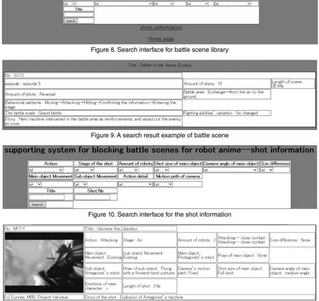
Our system has two interface for scene information and shot information. Figure 8 shows a search interface for battle scene. The user can search for scene informa- tion by using the keywords of categories, and can also obtain the details from search result as shown in Figure 9.
As illustrated in Figure 10, the interface of the shot in- formation is the same as the one for the scene informa- Shooing with handheld weapons such as a beam rifle
illustrated in Figure 5 is one of popular situation. We have analyzed 206 shots which include that, and there were 181 shots showing that robots are placing the weap- ons in front of their body when they are shooting. This indicates that robots usually put their weapons in front of their body before shooting.
We have analyzed 177 shots showing close combat in robot animations shown in Figure 6 and Figure 7. As a
Table 2. An example of shot record
Items Details
Shot number VVV2 -S17
Title Valvrave the Liberator
Shot length 00:05.08
Amount of robots 2
Main object Protagonist’s robot
Main object
Action Attacking
Action details Attacking--Close combat
Pose Flying with a forward-bent posture.
Sub object Antagonist’s robot
Sub object
Action Hutten
Action detail Hutten--Explosion
Pose None
Stage of the shot Air
Camera’s motion path Fix
Shot size Full shot
Camera angle medium angle
Story Explosion of Antagonist’s machine
Figure 4. A shot of shooting action
©Sunrise, PROJECT ANGE
Figure 5. A shot of shooting action with handheld weapon
©XEBECzwei, FAFNER EXODUS PROJECT, MBS
Figure 6. A shot of punch in a close combat
©BONES,PROJECT STAR DRIVER
Figure 7. A shot of a close combat
© Sunrise, MBS, Project Valvrave
Step 1: We briefly explained the participants how to use our camera blocking library in the form of a lecture.
Step 2: We presented one original story about fighting robots, and let them think about the scene structure.
Step 3: The participants design a camera blocking of given story by using our system. We counted the number of shots that were designed and how long it took for them to complete the camera blocking. A short questionnaire asked participants to rate our system.
5.2 Experimental Results
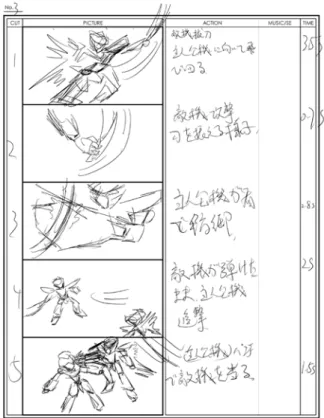
Table 3 shows the time required to complete the cam- era blocking and Figure 12 shows an example of camera blocking designed by a participant.
The inquiries show that each of the evaluators replied
“useful” as the evaluation of our system. We also re- tion. The user can also obtain the detailed shot informa-
tion as shown in Figure 11.
5. Experiment
5.1 Process of the experiment
In order to evaluate the effectiveness of our proposed system and its library, we have conducted an experiment in which four university students and graduate students produce camera blocking. The students are aiming to work in the video content industry and have an experi- ence with video production, but no experience about the production of robot anime. The purpose of this experi- ment is to confirm that the users can create the camera blocking as they intended by using our system. We do not evaluate the content itself, such as interesting or boring.
The experiment has the following four steps.
Figure 8. Search interface for battle scene library
Figure 9. A search result example of battle scene
Figure 10. Search interface for the shot information
Figure 11. A search result example of the shot information
16 Journal of Graphic Science of Japan Vol. 52 No. 4 /Issue no. 159 December 2018
ime production. We also made a library for classifying the behavioral patterns of robots and characters to be able to create a supporting system that can help to create bat- tle scenes by using this information. Experimental results suggest our system makes user without an experience of battle scene production to design the camera blocking of a given story.
Additional user experiments by participants with dif- ferent skills are required to improve our system from a broader perspective. Further studies for the 3D robot an- ime may extend the library and enables a wide range of the shot simulation.
Reference
[1] Kanematsu Y., Wang C., Motegi R., Mikami K., Kondo K.,
“Digitization of the Camera Work and a Supporting Technique of Composition Design based on Image Analysis”, Proceedings of annual conference 2014 (sp) of Japan society for Graphic Science (2014), pp.129-132.
[2] Nakajima T., Kanematsu Y., Motegi R., Mikami K., Kondo K., “A Support System of Composition Design based on Video Analysis”, ITE technical report 39, 14 (2015), pp.91- 94.
[3] Kaneko M., “Golden Rule of the Scenario Writing”, Born Digital, Inc. (2008).
[4] Kanematsu Y., “Support method for directing scheme based on movie analysis”, Ph.D. dissertation (2015), Tokyo University of Technology.
[5] Kaneko M. and Kondo K., “Golden Rule of the Character Making”, Born Digital, Inc. (2010).
[6] Sijll, J. V., “Cinematic Storytelling: The 100 Most Powerful Film Conventions Every Filmmaker Must Know”, Michael Wiese Productions (2005).
[7] Grass Valley K.K., “A Handbook of Video Production”, Genkosha (2014).
ceived some comments about the system such as “It is interesting to search the information about the robot ani- mation’s battle scenes and I can make a storyboard sim- ply by understanding the process of the battle with this system.” and “It is useful to amateurs who without the experience of the robot animation, I’m really expect the evolutionary system which can be used in the produc- tion.”.
5.3 Discussions
These results and evaluations suggested that our pro- posed system can help the users create scene structure and shot design more efficiently although they are no ex- perience about robot anime production.
6.Conclusions
The purpose of this study was to create a support sys- tem for designing battle scene structures. We therefore classified and analyzed scene characteristics as well as shot information in order to find the trends about camera blocking, camera work and composition in the robot an-
Table 3. Results of the experiment
Tester Time Amount of shot
1 37m09s 19
2 35m21s 17
3 39m57s 21
4 33m49s 23
Figure 12. Camera blocking created by participant.
●2018年 4 月15日受付
About the Authors
1. Hongyi XU, Master Course Student, Graduate School of Bionics, Computer and Media Sciences, Tokyo University of Technology, 1404-1, Katakura, Hachioji City, Tokyo, Japan, 192-0983
2. Yoshihisa KANEMATSU, Ph.D. in Media Science, Assistant Professor, Tokyo University of Technology.
3. Ryuta MOTEGI, Ph.D. in Media Science, Assistant Professor, Tokyo Metropolitan University.
4. Naoya TSURUTA, Ph.D. in Engineering, Assistant Professor at Tokyo University of Technology.
5. Koji MIKAMI, Ph.D. in Media and governance, Professor at Tokyo University of Technology.
6. Kunio KONDO, Dr. of Engineering, Professor at Tokyo University of Technology.
Abstract
In this study, we reproduced the Villa La Roche designed by Le Corbusier and the Casa Gilardi designed by Luis Barragan in a virtual environment which can control the color and texture as variable parameters. Then subjects evaluated the scale and the impression of the houses to clarify the spatial recognition characteristics affected by the color and texture. In the scale and the drawing test, the subjects wearing a VR headset evaluated the scale of the houses and drew the floor plan. As a result, there were a tendency that the Villa La Roche was recognized to be smaller, while the Casa Gilardi was recognized to be real scale or a little larger. In addition, the subjects wearing a VR headset evaluated the space impression by SD method. The results showed characteristic changes in space impression according to the color and texture.
Keywords: Spatial Recognition /Architecture /CG /Color /Texture / Virtual Reality
概要
本研究は,建築空間の色彩と肌理をパラメータとして制御 可能な没入型の仮想環境において,二つの住宅モデル(ル・
コルビュジエ設計のラ・ロッシュ邸およびルイス・バラガン 設計のヒラルディ邸)を再現し,被験者による空間スケール と印象評価実験から,色彩と肌理が空間認識に及ぼす影響を 明らかにした.スケール評価テストおよび描画テストでは,
被験者がVRヘッドセットを装着して,各住宅の実際のス ケールの選択と平面図の描画を行った.その結果,ヒラル ディ邸は実際のスケールと同じもしくはわずかに大きく認識 されるのに対し,ラ・ロッシュ邸は小さく認識される傾向が みられた.さらに,VRヘッドセットを装着して各住宅の空 間印象をSD法により評価した結果,色彩と肌理の違いによ る印象の差に特徴がみられた.
キーワード:空間認識/建築/ CG/色彩/肌理/バーチャ ルリアリティ
Kensuke YASUFUKU1, Takuro ENOMOTO2 and Hirokazu ABE3 安福 健祐1 榎本 拓朗2 阿部 浩和3
建築空間における色彩と肌理が空間認識に及ぼす影響
Spatial Recognition Affected by Color and Texture in Architectural Space
●研究論文
1. Introduction
When people experience architectural space, the color and texture of the material affect their spatial recognition.
Practice of decorating architectural elements in a variety of colors is called architectural polychromy and the hous- es designed by Le Corbusier (1887-1965) are listed as one of the features of architectural polychromy. The houses designed by Luis Barragan (1902-1988) also have the walls of brilliant colors such as pink, red and yellow.
Those houses were evaluated as a quiet and beautiful ar- chitecture with its texture. It was said that Barragan liked scraping mortar walls because the gradation due to deli- cate shadows enriched the expression as the finished sur- face of wall was more uneven.
Psychologist J. J. Gibson pointed out that density and changes in texture are important for spatial structure and depth perception[1]. In order to investigate human recog- nition characteristics affected by color and texture, vari- ous experiments have been conducted[2]-[4]. However, there are many parts that have not yet been clarified to evaluate architectural space. It is generally difficult to evaluate the effects of enormous patterns of color and texture in real space where people can move around free- ly. On the other hand, by using virtual environment, vari- ous parameters can be easily examined. Current virtual reality hardware and software enable us to move interac- tively in a high-quality virtual environment. A realistic building in virtual environment provides an experience close to the real building and can change the various pa- rameters.
The purpose of this study is to investigate the charac- teristics of spatial recognition affected by color and tex- ture of architectural space.
19
図学研究 第52巻 4 号(通巻159号)平成30年12月 19
lifetime and answered to light and water which were the subjects of his architecture. Figure 3 shows a screenshot of the virtual environment built on Unity.
2. Method
2.1. Virtual environment creating method
In the past few years, game engines and VR headsets have become common to build high quality virtual envi- ronments and provide immersive experience. A game en- gine is basically an integrated development environment to improve efficiency in video game development. How- ever, it is widely used for interactive 3D-CG application development, including VR contents and architectural vi- sualization. A VR headset is a goggle shaped device for experiencing VR contents.
In this study, we constructed a virtual environment with the game engine called “Unity” and provide an im- mersive space experience with a VR headset called HTC Vive. The feature of HTC Vive is room-scale VR which allows users to freely walk around 5 meters of diagonal space with “Lighthouse” laser base stations, that include motors that literally spin the lasers in order to detect the headset's position.
2.2. Investigated houses
The targets of this study are houses where the effects of color and texture are positively adopted in their de- sign. We reproduced the Villa La Roche (Paris, 1923) de- signed by Le Corbusier and the Casa Gilardi (Mexico City, 1978) designed by Luis Barragan in a virtual envi- ronment which can control the color and texture as vari- able parameters. Figure 1 shows each floor plan and the target area. The floor plans and the 3D-CG model were created with reference to[5] to[8]. The color and texture of the 3D-CG model were reproduced based on the photo- graphs and the explanation contained in the above refer- ences.
2.2.1. Villa La Roche
The color of the interior seen in the Villa La Roche is the earliest case of architectural polychromy advocated by Le Corbusier. The internal color scheme is seen in faces, openings, nonstructural elements, and is composed entirely of light pastel color. The finish is smooth. Figure 2 shows a screenshot of the virtual environment built on Unity.
2.2.2. Casa Gilardi
A variety of colors and textures are used in the Casa Gilardi. This house is regarded as a masterpiece of Bar- ragan who tackled the color and texture design in his
Figure 1: Floor plan of experiment.
Figure 2: Screenshot of the Villa La Roche.
Figure 3: Screenshot of the Casa Gilardi.
and then were asked to select the adjective pairs of 20 items that were close to the impression of the space on a scale of seven. If the impression faded away in the mid- dle of the evaluation, it was allowed to experience the target house additionally for 30 seconds.
2.3.4. Subjects
The experiment was conducted for 18 students major- ing in architecture between the ages of 22 to 26 (male: 9, female: 9 people). There was no subject who had seen the drawings of each house. The subjects were divided into three groups so that the experience in the scale test and the drawing test did not affect the space impression evaluation in which the subjects experienced the houses of three different color patterns (Table 1).
Since Group A took the scale test and the drawing test with white space, it was possible to evaluate the space impression of both the Villa La Roche and the Casa Gi- lardi without knowing the real color and texture. Group B took the scale test and the drawing test in the Villa Roche with real color and texture, and could evaluate the space impression of the Casa Gilardi without knowing the real color and texture. Group C reversed the target houses of group B in each test. The experiment period was December 12-20, 2016.
Table 1: Subject Group.
3. Results and Discussions 3.1. Scale test results
Figures 5 to 6 show the scale values evaluated by each subject as the real and comfortable space in the VR envi- ronment (the Villa La Roche and the Casa Gilardi) that enables the subjects to change the scale freely with a controller. The subjects (a to f) experienced the white 2.3. Experiment in virtual environment
Subjects wearing a VR headset evaluated the scale and the impression of the target houses in the virtual environ- ment to clarify the spatial recognition characteristics af- fected by the color and texture. This experiment was conducted by using two types of space: space without color and texture (referred to as “white space”) and space with color and texture. Figure 4 shows a scenery of the experiment.
Figure 4: Scenery of experiment.
2.3.1. Scale test
In the scale test, the subjects evaluated the scale of the houses. When each subject first entered the target house, the size of the space was different from the real size (ap- proximately 50 times larger). The subjects could control the scale of the house freely with the controller and were asked to select (1) the scale to feel "comfortable" and (2) the same scale as the real. The time limit was not set up.
2.3.2. Drawing test
In the drawing test, the subjects virtually experienced the target houses in the same scale as the real. At the same time, they were asked to draw the plan of the house on a 1/200 scale on a 5 mm squared paper. The drawing target area was a part of the floor plan and instructed as shown the gray area in Figure 1. The time limit was 10 minutes including the time for VR experience and the drawing. Wall of the floor plan was allowed to draw with a single line.
2.3.3. Space impression evaluation
In the space impression evaluation, the subjects virtu- ally experienced the three patterns of different colors in the target house. One of them was a real color scheme.
The subjects experienced each pattern for one minute,
21
図学研究 第52巻 4 号(通巻159号)平成30年12月