Investigation of Clustering Phenomena in Coupled Chaotic Circuits
Located in Three-Dimensional Space
Takumi Nara, Yoko Uwate and Yoshifumi Nishio
Dept. of Electrical and Electronic Engineering of Tokushima University 2-1 Minami-Josanjima, Tokushima-shi, Tokushima-ken 770-8506, Japan
Email:{nara, uwate, nishio}@ee.tokushima-u.ac.jp
Abstract—In this study, we investigate synchronization phe- nomena in coupled chaotic circuits which are connected by resistor. In addition, we investigate the difference of synchro- nization phenomena by distance information of coupled chaotic circuits and the difference of synchronization phenomena by increasing the number of coupled chaotic circuits. We confirm that the coupled chaotic circuits located in the near distance are synchronized at in-phase state, and the coupled chaotic circuits located in the far distance are not synchronized. Therefore, the clustering phenomena of coupled chaotic circuits are observed in two-dimensional space and three-dimensional space.
I. INTRODUCTION
Synchronization phenomena are the most familiar phe- nomena that exist in nature and they have been studied in various fields. Synchronization phenomena can be observed everywhere in our life. For example, we can confirm flashing firefly lights, metronome, beating rhythm of the heart and so on. Especially, synchronization phenomena of oscillatory network are interesting. In addition, complex networks attract attention from various fields. The feature of networks is the degree distribution, the path length and the clustering coefficient. Therefore, we focus on the clustering phenomena in this research.
In addition, clustering phenomena are one of interesting nonlinear phenomena observed from coupled chaotic circuits.
The clustering phenomena are to divide the set to be classified into subsets. Previously, many of the studies for clustering have been carried out for discrete time model [1]-[2]. However, analysis of using a continuous time model has not almost stud- ied. Therefore, we focus on research on clustering phenomena using electronic circuits in continuous time model.
On the other hand, coupled chaotic circuits that are elec- tronic circuits can be observed various amusing phenomena. In recent years, many methods are studied to apply to clustering and synchronization phenomena observed in coupled chaotic circuits for natural sciences. At the same time, synchronization phenomena and clustering have been studied associated with the chaos phenomena [3]-[4].
In this study, we focus on the clustering phenomena in the network of coupled chaotic circuits.
II. CIRCUITMODEL
Figure 1 shows the circuit model which is called Shinriki- Mori circuit. This circuit consists of a negative resistor, an inductor, two capacitors and dual-directional diodes.
-g v1 ig
id
v2
C1 C2
iL L
Fig. 1. Circuit model.
The circuit equation of this circuit is given as follows:
LdiL
dt =v2 C1
dv1
dt =gv1−idn
C2
dv2
dt =idn−iL.
(1)
The nonlinear function idn corresponds to the i−v char- acteristics of the nonlinear resistors consisting of the diodes and are given as follows:
idn=
Gd(v1−v2−V) (v1−v2> V) 0 (|v1−v2| ≤V) Gd(v1−v2+V) (v1−v2< V).
(2)
By changing the variables and parameters such that
iL=
√C2
LV x, v1=V y, v2=V z α=C2
C1, β=Gd
√ L
C2, γ=g
√L
C2, t=√ LC2τ
- 40 -
IEEE Workshop on Nonlinear Circuit Networks December 13-14, 2019
The normalized equation of chaotic circuit is given as follows:
dx dτ =z dy
dτ =αγy−αβf dz
dτ =βf−x.
(3)
The nonlinear functionf corresponds to the characterisitics of the nonlinear resistor consisting of the diodes and described as follows:
f =
y−z−1 (y−z >1) 0 (|y−z| ≤1) y−z+ 1 (y−z <1).
(4)
For the computer simulation, we set the parameters asα= 0.50,β = 20.00andγ= 0.50.
III. SIMULATIONRESULT
Definition of synchronization in this study is determined a voltage difference waveform. We define synchronization as the following Eq. (5).
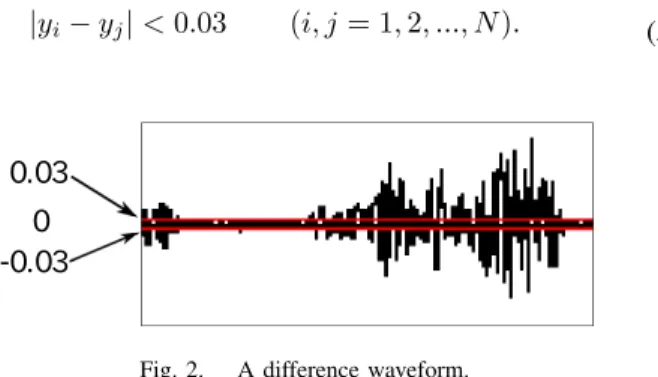
|yi−yj|<0.03 (i, j= 1,2, ..., N). (5)
0 0.03 -0.03
Fig. 2. A difference waveform.
Figure 2 is a different waveform which was observed in this simulation. The two lines in Fig. 2 correspond threshold which is given in Eq. (5). It is determined that wave within two lines which is the threshold is synchronization. Therefore, we investigate the percentage of synchronization during the specific time interval.
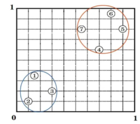
A. Network of seven chaotic circuits in two-dimensional space First, we investigate the synchronization phenomena and clustering phenomena when seven chaotic circuits are cou- pled in two-dimensional space. The location of seven chaotic circuits is shown in Fig. 3 and Table I.
Fig. 3. Location of seven chaotic circuits in two-dimensional space.
TABLE I
THE LOCATION OF CHAOTIC CIRCUITS IN THE TWO-DIMENSIONAL SPACE.
location X Y 1 0.15 0.35 2 0.10 0.10 3 0.30 0.20 4 0.70 0.60 5 0.90 0.80 6 0.80 0.95 7 0.55 0.80
All circuits connected each other by resistors. Figure 4 shows coupling method of the first chaotic circuit as an example.
1
2 3
4 5 6 7
γ12 γ13 γ14
γ15 γ16 γ17
i -g v1
ig
id
v2
C1 C2
iL
L
0 1
1
Fig. 4. Coupling between the first chaotic circuit and others.
We consider the coupled chaotic circuits:
dxi
dτ =zi
dyi
dτ =αγyi−αβf−α
∑N i,j=1
ri,j(yi−yj) dzi
dτ =βf−xi.
(6)
- 41 -
The nonlinear function f corresponds to the i-v character- istics of the nonlinear resistors consisting of the diodes and are given as follows:
f =
yi−zi−1 (yi−zi>1) 0 (|yi−zi| ≤1) yi−zi+ 1 (yi−zi<1).
(7)
where, iin the equation represents the circuit itself, and j is the coupling with other circuits. The parameter r represents the coupling strength between the circuits. In this simulation, we set the coupling parameter value ri,j to correspond the distance between the circuits by the following equation:
ri,j= q
(di,j)2. (8)
di,j represents the Euclidean distance between the i−th and thej−thcircuits. Further, the parameterqis the weight parameter that determines the coupling strengths. In this case, we set parameterq = 0.01.
Figure 5 shows the computer simulation results obtained from the seven chaotic circuits located as shown in Fig. 3.
From these results, we confirm that the first, second and third chaotic circuits are synchronized at in-phase state, and also the fourth, fifth, sixth and seventh chaotic circuits are syn- chronized at in-phase state. However, the first and the fourth chaotic circuits are not synchronized. From these results, the circuits can form two clusters defined by chaotic synchroniza- tion as shown in Fig. 6. The results of the synchronization rate are summarized in Table II. As a result, there was a difference in the synchronization rate within and between clusters, and it was proved that the clusters could be done numerically in addition to visual observation.
x
1x
2x
1x
3x
1x
4(a)1-2 (b)1-3 (c)1-4
x
4x
5x
4x
6x
4x
7(d)4-5 (e)4-6 (f)4-7
Fig. 5. Phase difference between seven circuits in two-dimensional space.
Fig. 6. The clustering result of seven chaotic circuits.
TABLE II
SYNCHRONIZATION RATE IN THE TWO-DIMENSIONAL SPACE.
maximum minimum average
Green 99% 73% 82.67%
Orange 99% 45% 65.67%
Between clusters 8% 7% 7.33%
B. Network of thirty chaotic circuits in three-dimensional space
Next, we investigate the case of three-dimensional networks.
Thirty chaotic circuits are located in three-dimensional, includ- ing the positional information. The location of thirty chaotic circuits is shown in Fig. 7 and Table III. In this case, we put the parameter q= 0.004724.
TABLE III
THE LOCATION OF CHAOTIC CIRCUITS IN THE THREE-DIMENSIONAL SPACE.
location X Y Z location X Y Z
1 0.15 0.05 0.15 16 0.80 0.20 0.15
2 0.20 0.25 0.30 17 0.85 0.15 0.05
3 0.35 0.35 0.25 18 0.70 0.60 0.95
4 0.25 0.25 0.05 19 0.90 0.80 0.85
5 0.30 0.15 0.05 20 0.80 0.95 0.75
6 0.05 0.20 0.10 21 0.75 0.85 0.70
7 0.15 0.30 0.15 22 0.85 0.80 0.85
8 0.05 0.05 0.25 23 0.60 0.60 0.60
9 0.20 0.05 0.35 24 0.80 0.65 0.90
10 0.25 0.10 0.20 25 0.65 0.80 0.80
11 0.35 0.05 0.25 26 0.65 0.65 0.85
12 0.25 0.05 0.35 27 0.95 0.95 0.95
13 0.75 0.15 0.25 28 0.90 0.65 0.75
14 0.80 0.25 0.10 29 0.70 0.85 0.65
15 0.95 0.30 0.35 30 0.75 0.80 0.85
- 42 -
Fig. 7. Location of thirty chaotic circuits in three-dimensional space.
Figure 8 shows the computer simulation results obtained from the thirty chaotic circuits located as shown in Fig. 7.
From these results, we confirm that the first and the second circuits are synchronized at in-phase state. However, the first chaotic circuit and the thirteenth chaotic circuit are not synchronized. Also the first chaotic circuit and the eighteenth chaotic circuit are not synchronized. Similarly, between the thirteenth and the fourteenth chaotic circuit are synchronized, between the eighteenth and the nineteenth chaotic circuit are synchronized. However, between the thirteenth and the eighteenth chaotic circuit are not synchronized. From these results, the circuits can form three clusters defined by chaotic synchronization as shown in Fig. 9. Further, the between clusters represent the respective synchronization rates among the three clusters. Similarly, the results of the synchronization rate are summarized in Table IV. As a result, there was a difference in the synchronization rate within and between clusters, and it was proved that the clusters could be done numerically in addition to visual observation.
x
1x
2x
1x
3x
1x
13(a)1-2 (b)1-3 (c)1-13
x
1x
18x
13x
14x
13x
15(d)1-18 (e)13-14 (f)13-15
x
13x
18x
18x
19x
18x
20(g)13-18 (h)18-19 (i)18-20
Fig. 8. Phase difference between thirty circuits in three-dimensional space.
Fig. 9. The clustering result of thirty chaotic circuits.
TABLE IV
SYNCHRONIZATION RATE IN THE THREE-DIMENSIONAL SPACE.
maximum minimum average
Blue 99 66 95.79
Green 99 43 76.60
Orange 94 36 82.87
Between clusters 29 8 12.56
IV. CONCLUSION
In this study, we investigated synchronization phenomena when the chaotic circuits are located in two-dimensional and three-dimensional space. Synchronization phenomena were seen between circuits at near distance, and synchronization phenomena could not be seen between circuits at far distance.
With these results, it was confirmed that the chaotic circuits were different from synchronization phenomena by distance information and the clustering phenomena were observed.
In the future works, we would like to increase the number of chaotic circuits and the cluster. Moreover, we consider that we would like to change of the dimensional space. We also would like to investigate changes in the clusters by changing the value of q.
REFERENCES
[1] K. Kaneko, “Clustering, Coding, Switching, Hierarchical Ordering, and Control in a Network of Chaotic Elements”,Physical D, vol. 41, pp.
137-172, 1990.
[2] L. Angelini, F. D. Carlo, C. Marangi, M. Pellicoro and S. Stramaglia,
“Clustering Data by Inhomogeneous Chaotic Map Lattice”,Phys. Rev.
Lett., 85, pp. 554-557, 2000.
[3] Y. Takamaru, H. Kataoka, Y. Uwate and Y. Nishio, “Clustering Phenom- ena in Complex Networks of Chaotic Circuits”, Proceedings of IEEE International Symposium on Circuits and Systems (ISCAS’12), pp. 914- 917, May 2012.
[4] T. Chikazawa, Y. Uwate, Y. Nishio. “Investigation of Spreading Chaotic Behavior in Coupled Chaotic Circuit Networks with Various Features”, Proceedings of RISP International Workshop on Nonlinear Circuits, Communications and Signal Processing (NCSP’17), pp. 337-340, Feb.
2017.