APCOM & ISCM 11-14
thDecember, 2013, Singapore
1
Contact analysis for an anisotropic half-domain with micropatterns considering friction
*Hideo Koguchi!, Shuma Suzuki
2, and Masahiro Taroura
31Department of Mechanical Engineering, Nagaoka University of Technology, Japan.
2Graduate School of Nagaoka University of Technology, 1603-1 Kamitomioka, Nagaoka, Niigata, Japan.
3Taiheikogyo Co. Ltd. Tokai, Aichi 476-0003, Japan
*Corresponding author: [email protected]
Abstract
In the present study, a contact problem between a spherical indenter and a half-anisotropic elastic region with a micropattern is solved under normal and tangential forces considering friction.
Surface Green's function, the discrete convolution and the fast Fourier transform (DC-FFT) method are used to calculate displacements on a contact area, and the conjugate gradient (CG) method is employed for calculating a contact pressure, the contact area, shear tractions, and a stick-slip region, respectively. The influences of the shape and density (the ratio of the pattern area per a unit area) of the micropattern and of material anisotropy in the substrate on the friction property for the substrate are investigated. In this study, the substrate with circle- and square-micropatterns are used for the analysis. As the result, it is found that the shear traction concentrates at the edges and corners of circle- and square-patterns, respectively. The apparent friction coefficient varies with the direction of the anisotropic principal axis.
Keywords: Contact problem, Anisotropic material, Friction, Micropattern.
Introduction
By machining a micropattern on the surface of material, the friction property on the surface is desired to control as we design. Then, the functional enhancement in various manufacturing processes can be promoted. For example, there are needs to control an inflow and a transformation to the die of the work piece partially by machining a micropattern for a surface of the press die and blank holder. However, we do not yet understand enough the effect of pattern shapes on friction properties or the advantage that give a micropattern. Therefore, the present study investigates the friction property through a contact analysis between a spherical indenter and a half-anisotropic elastic region with the micropattern. In particular, the normal and tangential forces are applied to the surface of the anisotropic and isotropic elastic body, and investigated the relationship between the frictional force and the micropattern. Vlassak et al. (2003) analyzed a contact problem, which the indenter in an arbitrary shape is penetrated in the normal direction for the surface of the anisotropic material. In addition, Lin et al. (2008) analyzed a contact problem of a three- dimensional rough surface, and He et al. (2004) performed a three-dimensional contact analysis of the rough surface with an arbitrary geometry. Cattaneo (1938) and Mindlin (1949) first established mathematical models for analyzing a partial slip problem in an elastic contact. They assumed that the magnitude of shear traction in a contact area could not exceed a static friction limit. Recently, Ciavarella (1998) extended Cattaneo-Mindlin's partial slip model to plane contact problems.
However, the contact of dissimilar materials does not obey the classic theory of the Cattaneo-
Mindlin model, in which the effects of shear tractions on the normal displacement were not
considered. It is difficult to derive an analytical solution for the contact problems with coupled
normal and tangential loads. Therefore, Kalker (1977) proposed the method for analysis using the
variational principle, instead of solving a contact problem analytically. Moreover, Chen and Wang
(2008) proposed a method for analysis in the case considering a partial slip on a three-dimensional
contact problem. Dini et al. (2010) conducted a contact analysis to the surface with many
hemispherical projections.
2
In the present paper, a partial slip contact problem on half-anisotropic elastic bodies with a micropattern is analyzed. The conjugate gradient (CG) method, the discrete convolution and the fast Fourier transform (DC-FFT) are used for the contact analysis. Distributions of contact area and contact pressure are calculated using the CG method. The surface displacement for a contact pressure is calculated using the DC-FFT method. Furthermore, the influence coefficient is obtained using a surface Green function in a three-dimensional anisotropic elastic body. As a result, a ratio of the apparent stick-slip area and the friction coefficient of the surface with a micropattern are obtained for various directions of horizontal external force. In addition, the apparent friction coefficient for the surface with patterns is analyzed.
Theory and Descriptions
A model for contact problem between a rigid spherical ball and a surface with a micropattern is shown in Fig. 1. The x- and y-axes are set on the surface, while the z-axis directs inwards the substrate. The ball indenter is pressed onto the substrate by a normal load, P
0, in the z-direction.
Tangential loads, F
xand F
y, are applied to the ball in parallel directions to the x- and y- axes. The contact interaction results in a balance between normal pressure p, shear tractions q
xand q
yat the interface. The contact analysis of the semi-infinite isotropic elastic body considering friction was conducted by Mindlin (1949), and the validity of the result was checked in experiment, too. More general contact model is summarized as follows,
u
x( ) x, y u
y( ) x, y u
z( ) x, y
!
"
##
$ #
#
%
&
##
' #
# (
!
x!
y!
z!
"
##
$ #
#
%
&
##
' #
#
=
s
x( ) x, y s
y( ) x, y g x, ( ) y ( h
0( ) x, y
!
"
##
$ #
#
%
&
##
' #
#
, (1)
where u
x, u
y, and u
zare the surface displacement under external forces in the direction of three axes, !
x, !
y, and !
zare the rigid body displacements, respectively, s
xand s
ythe relative slip distance parallel to the x- and y-axes, h
0is the initial surface gap, and g the surface gap between the indenter and the substrate after loading. The meanings of variables are shown in Fig. 2. Furthermore, the rigid body displacements !
x, !
y, and !
zfor isotropic materials are derived from the equations below, !
x= !
0{ 1 ! ( 1 ! Fx µ
fP
0)
2 3} , !y = !
0{ 1 ! ( 1 ! Fy µ
fP
0)
2 3} , (2) !z = 9P
02( 1! !
2) 16RE
2, (3) where
= !
0{ 1 ! ( 1 ! Fy µ
fP
0)
2 3} , (2) !z = 9P
02( 1! !
2) 16RE
2, (3) where
= 9P
02( 1! !
2) 16RE
2, (3) where
!
0= 3 µ
fP
0( 2 ! " ) ( 1 + ! ) 8aE , (4) a is a radius of the contact area,
P0
Fx
x
z Rigid ball
Substrate y
Normal load
Tangential force
Micropattern Fy
P0
Fx
x
z
!z
!x
g
ux
uz
sx
h0
Stick region Slip region
Rigid ball
Substrate
Figure 1. Model of contact analysis Figure 2. Description of contact situation
3
a = { 3RP
0( 1 ! !
2) 4E }
1 3, (5) R is a radius of rigid ball, E is Young's modulus of elastic body, and " is a Poisson’s ratio of elastic body.
In contact analysis, we determined the contact area, pressure and shear traction so as to satisfy the conditions of the following formula using Eq. (1).
Let
g x, ( ) y = h
0( ) x, y ! !
z+ u
z( ) x, y . (6) The contact pressure p is thought as follows,
g x, ( ) y = 0 : p x, ( ) y ! 0 ( In contact )
g x, ( ) y > 0 : p x, ( ) y = 0 ( In separation )
"
# $
%$ , (7)
"
!p x, ( ) y dS = P
0, (8)
where # is the contact area, and P
0is the normal load.
The shear tractions in the stick and slip regions are assumed to obey the following conditions:
In the stick region: q
x2( ) x, y + q
y2( ) x, y ! µ
fp , and s
x2( ) x, y + s
y2( ) x, y = 0 (9) In the slip region: q
x2( ) x, y + q
y2( ) x, y = µ
fp , and s
x2( ) x, y + s
y2( ) x, y ! 0 (10) "
!q
i( ) x, y dS = F
i, i =x, y, (11) where the shear tractions q
iis the product of the friction coefficient µ
fand the contact pressure p.
Furthermore, the elastic displacement in the contact region is calculated in order to perform contact analysis. If the force q = (q
x, q
y, p) is applied to a contact surface, the surface displacement u is calculated from the following equation,
u ( ) x, y = K ( x ! x
s, y ! y
s) q ( x
s, y
s) dx
sdy
s"
## (12)
where (x, y) is an observation point, (x
s, y
s) is a source point of force, K is the displacement of the observation point when unit concentration load acts to a source point. Generally, K is expressed in a matrix form. The response function for displacement will be described later. Applying the two- dimensional Fourier transform to Eq.(12) yields u ˆ = K ˆ ! q ˆ , where the two-dimensional Fourier transform is defined by
f ˆ ( !
1, !
2) =
"#$
"##f x, ( ) y e
i(!1x+!2y)dx dy
$
#(13)
Calculation is carried out iteratively so that the normal load P
0and tangential forces F
xand F
ywhich are given as a prior condition may satisfy Eqs. (8)-(12). Moreover, the distributions of
contact pressure p and shear tractions q
xand q
yin a contact region are calculated. In order to solve
the basic equation for a contact problem, the field containing a contact surface is divided by a grid.
4
Grid intervals of the x- and y- directions are set to $ x and $ y. When the coordinates of an arbitrary grid point on the field are (i $ x, j $ y), the coordinates of the point are represented as (i, j). The algorithm for resolving the shear tractions proposed by Wang et al. (2010) is used in this study. This method is used for the repetitive calculation considering the coupling effect of contact pressure and shear traction. Furthermore, the stick-slip region and shear traction of the contact region are determined simultaneously.
In this study, the displacement in the contact area is calculated using the DC-FFT method. The displacement under the shear tractions q
x(i, j) and q
y(i, j) is obtained by the inverse Fourier transform of Eq. (13). Thus,
u
x( ) i, j u
y( ) i, j u
z( ) i, j
!
"
##
$ #
#
%
&
##
' #
#
= IFFT K ˆ
qx
ux
i, j
( ) K ˆ
qyux
i, j
( ) K ˆ
pux( ) i, j
K ˆ
qx
uy
i, j
( ) K ˆ
qyuy
i, j
( ) K ˆ
puy( ) i, j
K ˆ
qx
uz
i, j
( ) K ˆ
qyuz
i, j
( ) K ˆ
puz( ) i, j
(
)
* *
* *
*
+
, - - - - -
q ˆ
x( ) i, j q ˆ
y( ) i, j p i, ˆ ( ) j
!
"
##
$ #
#
%
&
##
' #
#
!
"
# #
$
# #
%
&
# #
'
# #
, (14)
where IFFT denotes the inverse Fourier transform, and ^ expresses the Fourier transform of each function. Equating Eq. (14) to the x- and y- component of Eq.(1) yields
IFFT
K ˆ
qx
ux
i, j
( ) K ˆ
qyux
i, j
( ) K ˆ
pux( ) i, j
K ˆ
qx
uy
i, j
( ) K ˆ
qyuy
i, j
( ) K ˆ
puy( ) i, j
!
"
# #
#
$
%
&
&
&
q ˆ
x( ) i, j q ˆ
y( ) i, j p i, ˆ ( ) j '
( ))
* ) )
+ , )) - ) ) '
( ))
* ) )
+ , )) - ) )
. !
x!
y' ( )
*) + , ) -)
= s
x( ) i, j s
y( ) i, j '
( )
*)
+ , ) -)
, (15)
where pressure distribution p(i, j) is provided from the contact problem of only normal load. Then, shear tractions q
xand q
ycan be determined from Eq.(15) by using the CG method coupling with constraint conditions (Eqs.(9) and (10)).
Once the shear tractions q
xand q
yare obtained from the above procedure, the displacements u
zfor q
xand q
y, respectively, can be determined in terms of the influence coefficients by using the DC-FFT method. Then, the surface vertical gap g is updated by adding the displacements due to the shear tractions. Furthermore, the CG method is also employed to renew the contact pressure, and the new pressure is used for further update of the shear tractions.
Now, we need to derive the influence function for a semi-infinite anisotropic region. We consider that a force f=(f
x, f
y, f
z) is applied to the coordinate origin. The equilibrium equation for anisotropic materials can be expressed using the displacement, u
i:
C
ijklu
k,lj= 0 . (16)
y
Semi-infinite
anisotropic elastic region x
z
f = ( fx, fy, fz)
( 0, 0, 0)
Figure 3. The coordinate system for an influence function
5
The two-dimensional spatial (x
1-x
2) Fourier transform is applied to Eq.(16). Then, an ordinary differential equation of displacement is derived. The general solution of the differential equation is assumed to be ˆu = ae
!ip!x3. Where p and a satisfy the following eigenrelation:
{ Q + p R ( + R
T) + p
2T } a = 0 (17) where Q
ik=C
ijksn
jn
s, R
ik=C
ijksn
jm
s, and T
ik=C
ijksm
jm
swith n=[n
1, n
2, 0]=[cos % , sin % , 0]
T, m=[0,0,1]
T. The angle % is used in the variables ( &
1, &
2) = ( ' n
1, ' n
2) of the Fourier transform and taken from the
&
1axis. Finally, the displacement obtained from the inverse Fourier transform is expressed as follows:
u(x
1, x
2, x
3) = i 4!
21
" A e
!ip*!x3B
!1!"
"
#
!"
"
# fe
!i(!1x1+!2x2)d!
1d!
2(18) where A=[a
1, a
2, a
3], B=[b
1, b
2, b
3], 〈
e"ip*!x3〉 = diag[
e"ip1!x3,
e"ip2!x3,
e"ip3!x3], and
b
j= ( R
T+ p
jT ) a
j.
Results and Discussions Result of isotropic material
For a verification of the validity of the result of analysis, the same problem as Wang et al. (2010) is analyzed. The condition for analysis is shown in Table 1(a). The Boussinesq's solution for an isotropic elastic body is used for calculating the response coefficient of traction and pressure.
Distributions of the contact pressure and shear tractions are shown in Figs. 4(a) ~ (c). In addition, the contact pressure and shear tractions are normalized by the maximum pressure of Hertz contact theory, p
H= 860MPa, and coordinates are normalized by the contact radius of Hertz contact theory, a= 0.105 mm. In this analysis, the displacement in a normal direction to the surface induced by the tangential force that acts on the surface of a half-infinite domain is also taken into consideration.
Therefore, the maximum contact pressure causes at the position where the maximum shear traction q
xshown in Fig.4(b) occurs. The distributions of contact pressure and shear traction are agreed with the results of Wang et al. (2010).
Results of anisotropic material
Distributions of the contact pressure and shear tractions on the plane of Fe(111) are shown in Figs.
5(a)~(c). Moreover, pressure and shear tractions were normalized by the maximum pressure of Hertz contact theory p
H= 931.62MPa, and coordinates were normalized by the contact radius of Hertz contact theory a = 0.10124mm. As compared with the result of isotropic material, the maximum and minimum values of the contact pressure and shear tractions in the anisotropic material are similar to those in the isotropic Fe. However, the shapes of the distribution are different,
(a)Normalized contact (b) Normalized shear (c) Normalized shear pressure p/p
Htraction q
x/p
Htraction q
y/p
HFigure 4. Contour plots of normalized contact pressure and shear tractions by
p
H=860.03MPa and a=0.10537mm
6
but the difference of absolute values of the shear tractions is small. Here, Young's moduli and Poisson’s ratio for anisotropic materials Fe(111), Cu(111) and Ni(111) are calculated using E
(111)= 4/(2s
11+ 2s
12+ s
4) and "
(111)= -(s
11+ 5s
12- s
44/2) (3s
11+ 3s
12+ 3s
44/2), respectively, where s
11, s
12and s
44are elastic compliance of materials.
At first, a contact analyze for the surface of Cu (isotropy, anisotropy) and Ni (isotropy, anisotropy) which have four kinds of micropatterns shown in Fig.6 under the condition (c) shown in Table 1 is
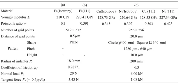
Table 1. Condition for analysis
(a) (b)
Fe(Isotropy) Fe(111) Cu(Isotropy) Ni(Isotropy) Cu (111) Ni (111) 210 GPa 220.41 GPa 128.73 GPa 220.64 GPa 128.53 GPa 227.34 GPa
0.3 0.391 0.345 0.302 0.503 0.423
Shape
Pitch - -
Height - -
0.3 (c)
Young's modulus E Poisson’s ratio !
Coefficient of friction µf
Material
Number of grid points 256 ! 256
20.0 µm
Circle("400 µm),Square(□340 µm) 1280 µm,640 µm
30.0 µm Distance of grid points
Pattern
Radius of indenter R 200 mm
Normal load P0 20 N 6.00 kN
Tangent force Fx (= 0.6µf P0) 3.43 N 1.08 kN
512 ! 512 0.5µm Plane
18.0 mm 0.28571
Table 2. Material properties used in the analysis (GPa)
C11 C12 C13 C15 C22 C23 C25 C33 C44 C46 C55 C66
Fe(111) 300.1 111.6 97.26 20.26 300.1 97.26 -20.26 314.4 79.93 -20.26 79.93 94.25 Cu(111) 218.6 103.7 86.51 24.32 218.6 86.51 -24.32 235.8 40.25 -24.32 40.25 57.44 Ni(111) 325.7 129.0 103.2 36.58 325.7 103.20 -36.58 351.6 72.47 -36.58 72.47 98.33
(a)Normalized contact (b) Normalized shear (c) Normalized shear pressure p/p
Htraction q
x/p
Htraction q
y/p
HFigure 5. Contour plots of normalized contact pressure and shear tractions by p
H=931.62MPa and a=0.10124mm
d pt
θ
d
θ pt
pt
L L
θ
pt
L L
θ
(a) Circle A (b) Circle B (c) Square A (d) Square B
Figure 6. Geometry and size of micropatterns
7
carried out, and the friction property for different micropatterns is investigated. Elastic constants for the anisotropic material are shown in Table 2. Figure 7 demonstrates the distributions of shear traction, q
x, and the contact pressure p on the surface of Cu(111). In case of Circle A, the shear traction q
xconcentrates at the edge of each circle, and a positive shear traction occurs at the right side of the circle like Fig.4(b), since the external force which is applied to the rigid indenter directs in the positive direction of the x-axis. Large shear traction occurs near the center in the whole contact area. In case of Circle B, the shear traction q
xis less than that in Circle A (Fig.7(b)), and the concentration of q
xat the edge reduces moderately. This is attributed to the increase of pattern density. This is caused by the increase of contact area and the decrease of average contact pressure.
There is no space to show the results for Squares A and B. Similar results are deduced for square patterns, furthermore, for Ni(111).
Slip distance and stick region
The maps of slip distance, s
xy, for each surface pattern are shown in Fig.8. The stick region indicates the region of s
xy=0. For Circle A, it is found that the slip distance increases in the direction of the applied force within the region of a lower contact pressure, and the stick region exits at the opposite side of the slip region. Comparing the stick region with the distribution of shear tractions, q
xand q
y, it is found that the shear tractions vary significantly within the stick region. Figure 8(b) shows the map of slip distance for Circle B. It is found that the width of stick region in Circle B is less than that in Circle A. Next, comparing Fig.8(c) with Figs.8(a), (b) and (d), it is found that the stick region for square patterns is similar to that for circular patterns, and the width of stick region decreases with the increase of pattern density. Although the maximum slip distance does not so much vary for all patterns.
Apparent friction coefficient
It is very hard to determine a friction property for each pattern due to the different tendency of the ratio of stick region against the pattern density. Then, a friction coefficient is investigated for the apparent contact area. An analytical solution for contact problem with anisotropic substrate considering friction cannot be available until now. So, the friction coefficient is estimated using the expression for isotropic materials in the study. When material is isotropic, the friction coefficient is obtained from
µ
a= !
xa
3K
E{ P
0( a
2! c
2) } (19)
(a) Contact pressure (b) Shear traction (c) Contact pressure (d) Shear traction p (GPa) : Circle A q
x(GPa) : Circle A p (GPa) : Circle B q
x(GPa) : Circle B
Figure 7. Contour maps of contact pressure and shear tractions : Cu(111)
(a) Circle A (b) Circle B (c) Square A (d) Square B
Figure 8. Contour maps of slip distance : Cu(111)
8
where K
E=8E{3(1+ " )(2- " )}, " is Poisson’s ratio, E is Young’s modulus for the isotropic substrate.
When the substrate is an isotropic flat surface, the friction coefficient calculated using Eq.(19) is 0.3.
When material is anisotropic, K
Eis composed of anisotropic elastic moduli. We do not know the form until now. The value of K
Eis determined from the data of the flat anisotropic substrate for different directions of applied force. The obtained values of K
Eare shown in Fig.9(a). In the present analysis, the arrangement and direction of the patterns are fixed, and the direction of applied horizontal force is rotated 15º by 15º until 180º with respect to the z-axis. Then, the influence of pattern on the apparent friction coefficient, µ
a, is investigated. The results are shown in Fig.9(b). It is found that the apparent friction coefficient for the surfaces with patterns is larger than that for the isotropic substrate with the flat surface. It is found that the value of friction coefficient for the surface with high pattern density is less than that with low pattern density. This is due to the increase of contact pressure in low pattern density. The influence of pattern shape on the friction coefficient can be a little observed.
Conclusion
In the present study, a contact problem between a rigid spherical indenter and a half-anisotropic elastic region with the micropattern was analyzed under normal and tangential forces considering friction. Furthermore, the apparent friction property for the surface with a micropattern was investigated. From the results, the following conclusions can be drawn:
(1) The difference of absolute values of the shear tractions between isotropic material and anisotropic material were not so much large. However, the shapes of the map for shear tractions were different.
(2) For the surface with the micropattern, the contact pressure concentrated at the edge of each pattern, and the shear tractions also concentrated at the sites corresponding to the contact pressure.
(3) The apparent friction coefficient for a high density of micropattern was less than that for a low density.
References
Vlassak, J.J., Ciavarella, M., Barber, J.R., Wang, X., (2003), The indentation modulus of elastically anisotropic materials for indenters of arbitrary shape, J. Mech. Phys. Solids, 51, pp.1701–1721.
Lin Y. and Ovaert T.C., (2008), Three–dimensional rough surface contact model for anisotropic materials, J. Tribol., 130, 021402.
He L. and Ovaert T.C., (2004), A rough surface contact model for general anisotropic materials, J. Tribol., 126, pp.41–
49.
Cattaneo, C., (1938), SulContatto Di Due CorpiElastici: Distribuzione Locale DegliSforzi, Rend. Accad. Naz. Lincei, 27, pp. 342–348, 474–478, 434–436.
Mindlin, R. D., (1949), Compliance of Elastic Bodies in Contact, J. Appl. Mech., 16, pp. 259–268.
Ciavarella, M., (1998), The Generalized Cattaneo Partial Slip Plane Contact Problem. I—Theory, Int. J. Solids Struct., 35(18), pp. 2349–2362.
Kalker, J. J., (1977), Variational Principles in Contact Elastostatics, J. Inst. Math. Appl., 20, pp. 199–219.
Chen, W. W., and Wang, Q., (2008), A Numerical Model for the Point Contact of Dissimilar Materials Considering Tangential Tractions, Mech. Mater., 40(11), pp. 936–948.
Dini, D. Hill, D. A.,2009, Frictional Energy Dissipation in a Rough Hertzian Contact, J. Tribol.,131(2), 021401.
Wang, Z. J., Wang, W. Z., Wang, H., Zhu, D., and Hu, Y. Z., (2010), Partial Slip Contact Analysis on Three- Dimensional Elastic Layered Half Space, J. Tribol., 132(2), 021403.