BRIEF PAPER
Special Section on Recent Development of Electro-Mechanical DevicesRelationships between Break Arc Behaviors of AgSnO 2 Contacts and Lorentz Force to be Applied by an External Magnetic Force in a DC Inductive Load Circuit Up to 20V-17A
Seika TOKUMITSU†,Nonmember andMakoto HASEGAWA†a),Senior Member
SUMMARY When AgSnO2contacts were operated to break an induc- tive DC load current of 14V-12A, 20V-7A or 20V-17A at a contact opening speed of 10mm/sec or slower, application of an external magnetic field re- sulted in reductions in break arc durations even without magnetic blowing.
Simple estimation of Lorentz force to be applied onto arc column revealed that a certain minimum magnitude of Lorentz force seems to be required for initiating arc blowing. Certain relationships between the Lorentz force magnitude and the timing of metallic-to-gaseous phase transition were also found to exist.
key words: magnetic blowing, break arc, AgSnO2contacts
1. Introduction
Break arc discharges are one of serious phenomena during operations of electrical contacts, which may lead to contact failures. In order to realize longer lifetime and/or better per- formances, reductions in break arc durations are strongly re- quired. For such a purpose, increases in contact opening speeds as well as application of external magnetic field are often employed[1]–[7]. However, the authors’ previous re- search results revealed that complicated phenomena can be observed and further research work is needed[8]–[14].
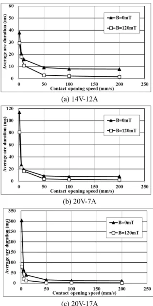
Figure 1 shows exemplary experimental results of mea- sured break arc duration characteristics of AgSnO2contact pairs in an inductive DC load circuit at 14V-12A, 20V-7A and 20V-17A, respectively (Log-log scale versions of these graphs can be found in Ref.[15]). By opening contacts at faster speeds, break arc durations are surely reduced. Satis- factory effects of application of external magnetic field are found especially with faster opening speeds, in which mag- netic blowing of arc column can be observed (i.e., arc col- umn is moved out of a contact gap in a curved shape due to Lorentz force, as if “blown out”, and extinguishes there).
When looking at Fig. 1 more carefully, reductions in break arc durations by magnetic field application can also be found with slower contact opening speeds. In this case, however, magnetic blowing cannot be observed (i.e., arc col- umn remains in a contact gap until its extinction, although there may be some movements over contact surfaces), im- plying possible some other influences of external magnetic field.
Manuscript received December 28, 2018.
Manuscript revised March 7, 2019.
†The authors are with Chitose Institute of Science and Tech- nology, Chitose-shi, 066–8655 Japan.
a) E-mail: [email protected] DOI: 10.1587/transele.2019EMS0001
Fig. 1 Exemplary characteristics of break arc durations of AgSnO2con- tacts in an inductive DC load circuit with/without application of external magnetic field of B=120mT[15].
In this paper, for the purpose of further investigating the phenomena, arc movements were observed with a high- speed camera, and Lorentz force to be applied onto the arc column was estimated based on arc current waveforms.
Copyright c2019 The Institute of Electronics, Information and Communication Engineers
The same switching mechanism as in the authors’ previous research work was also employed in this study. A motor- ized stage driven by an AC serve motor was used to real- ize switching operations of the mounted test contact pair.
AgSnO2contacts (Ag88%-SnO212% with no additives, pre- pared by internal oxidation) of a solid rivet-type with a head diameter of about 1mm were used. The head of a stationary electrode (served as a cathode) was attached onto a metal plate, while the head of a movable electrode (served as an anode) was attached onto a spring plate made of phosphor bronze. Before the test, the surfaces of both electrodes were polished with #1000 sandpaper and then wiped with methyl alcohol. Thereafter, the contact pair was mounted onto the switching mechanism. At the closed position, the movable anode electrode was slightly pushed backward by the mat- ing stationary cathode electrode, thereby resulting in slight bending of the spring plate (an electrode assembly arm for the movable anode electrode) due to its elasticity. This may cause some wiping between the electrode surfaces as is usual in commercial relays.
The inductive load circuit in this study included an in- ductive component of about 5.7 mH. Due to such an in- tentional inductive component, influences of unregulated inductive components in the circuit (e.g., stray inductance components due to wirings) were believed to be mitigated.
No specific control for the load current flow was employed during the switching operations, and thus, both break and make discharges were actually occurred. Only effects of break arc discharges were investigated in this study.
One piece of neodymium magnet (with 0.5 cm in height and 1.5 cm in diameter) was placed at about 0.5 cm away from the contact gap position for the purpose of real- izing external magnetic field application at the contact gap.
With such a placement, the measured magnetic flux density at the contact gap was measured to be about 120 mT.
Load condition was set as either of 14V-12A, 20V-7A and 20V-17A. At each of these load conditions, the test con- tact pair was operated at least 10 switching operations at the contact opening speed of 1 mm/s, 50mm/s or 200mm/s.
Voltage and current waveforms of break arcs were measured with a digital storage-scope (Yokogawa DL1620). In addi- tion, arc column behaviors were observed and recorded as a movie with a high-speed camera (Photoron FASTCAM Mini AX200). It should be noted that in this study, arc volt- age/current waveform measurements and arc movement ob- servation were not conducted simultaneously in the same operations.
3. Experimental Results
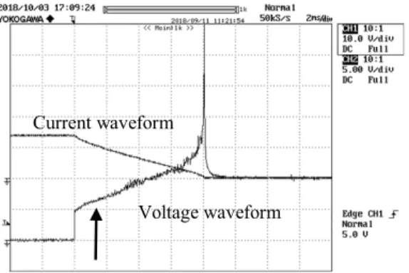
3.1 Arc Voltage/Current Waveforms and Arc Behaviors Figure 2 shows typical voltage/current waveforms of ob- served break arc. An upward arrow indicates the transition
Fig. 2 Exemplary voltage/current waveforms with magnetic field of B= 120mT at 20V-7A with the opening speed of 50mm/s.
Fig. 3 Exemplary arc behavior images almost immediately before ex- tinction without/with the applied magnetic field of B=120mT at 14V-12A with the opening speed of 50mm/s.
point from metallic to gaseous phase, determined by finding out the end point of the flat voltage level in the arc voltage waveform, which will be further explained later. Although not shown in the Fig. 2 case, re-striking phenomena were sometimes observed when the applied magnetic field.
Figure 3 shows photo images derived from the ob- served movies, respectively indicating typical arc behaviors almost immediately before extinction without/with the ap- plied external magnetic field.
In the case of the 14V-12A and 50mm/s operations, magnetic blowing as shown in Fig. 3 (b) was always ob- served when the external magnetic field was applied, while without the magnetic field, arc column remained within the contact gap space, as shown in Fig. 3 (a). Further observa- tions revealed that in the case where magnetic blowing was not observed even with the applied magnetic field, arc col- umn was likely to move to the lower portion within the con- tact gap during arc burning and extinguish there, as shown in Fig. 4.
The following tendencies, as summarized in Table 1, with the applied external magnetic field were found in this study.
In brief summary, with faster opening speeds, arc blow- ing was likely to be surely observed, while with slower opening speeds, arc column was sometimes not blown out even with the applied magnetic field. Such tendencies were more significant with smaller load current conditions. For example, with 1mm/sec contact opening speed, arc blowing
Fig. 4 Arc behavior image almost immediately before extinction with the applied magnetic field of B=120mT but no magnetic blowing at 20V- 7A (Note this image was captured with the opening speed of 10mm/s).
Table 1 Magnetic blowing characteristics under several different condi- tions.
was observed in all cases with 20V-17A, but with smaller current levels, arc blowing was not observed.
3.2 Estimation of Lorentz Force Applied onto Arc Column The above-mentioned tendencies imply that application of external magnetic field seems to have some complex influ- ences on reductions of break arc durations and arc behav- iors. Especially, focus was placed on the case where break arc duration was actually shortened but arc column was not blown out even with the applied external magnetic field. In order to obtain further understanding of such phenomenon, expected Lorentz force was calculated from the measured arc current waveform.
Lorentz forceFLcan be expresses as follows:
FL=I·B·L (1)
where I is an arc current value, B is an applied magnetic flux density, andLis an arc length. It is generally difficult to obtain the exact arc length value. However, prior to the moment of magnetic blowing, an arc length can be assumed to be almost equal to a contact gap length, which in turn can be calculated by multiplying the contact opening speed value and the elapsed time from arc ignition.
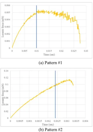
Upon reviewing the calculation results obtained by us- ing Eq. (1), there found two different patterns with respect to the timing of the metallic-to-gaseous transition and the changes in the Lorentz force. The transition point from metallic to gaseous phase was determined by finding out the end point of the flat voltage level in the arc voltage wave- form (see an arrow in Fig. 2) which was the same criteria employed in the authors’ previous research work. Figure 5 shows those exemplary two patterns. Specifically, in Pattern
Fig. 5 Relationships between the timing of the metallic-to-gaseous tran- sition and the changes in the Lorentz force.
Fig. 6 The average maximum values of the estimated Lorentz force for the respective operating conditions.
#1, the metallic-to-gaseous transition timing (indicated by a blue straight line) is close to the maximum on the Lorentz force changes. Among the tested operating conditions, all cases with the contact opening speed of 1mm/sec, in ad- dition to 20V-17A@50mm/sec, corresponded to this pat- tern. In Pattern #2, the metallic-to-gaseous transition occurs while the Lorentz force is still becoming lager.
It should be noted that the trace in Fig. 5 (b) included the calculation results after occurrence of magnetic blowing.
Furthermore, average maximum values of the esti- mated Lorentz force are shown in Fig. 6. If the value of 0.1mN is set as the threshold level in the maximum esti-
- The maximum Lorentz force is smaller than 0.1mN all cases with the contact opening speed of 1mm/sec, and 20V-7A@50mm/sec
- The maximum Lorentz force is larger than 0.1mN 14V-12A@50mm/sec, 20V-17A@50mm/sec, and all cases with the opening speed of 200mm/sec
4. Discussions
Based on the above-mentioned tendencies relating to the Lorentz force changes, briefly speaking, the slower open- ing speed conditions were likely to correspond to Pattern
#1 and the faster opening speed conditions were likely to correspond to Pattern #2. In addition, the operating con- ditions with slower speeds or smaller current levels were likely to have a small magnitude of Lorentz force, while the faster speed or larger current conditions were likely to have larger magnitude of Lorentz force. The non-blown cases were found in the group of smaller maximum Lorentz force with the maximum level of 0.1mN or less.
From the above, the tested operating conditions can be divided in some groups with respect to the two patterns of the metallic-to-gaseous transition timing and the maximum magnitude of Lorentz force. The non-blown cases even with the applied magnetic force can be basically classified in the group of Pattern #1 and with the maximum magnitude of Lorentz force smaller than 0.1mN.
Thus, it may be able to determine whether or not magnetic blowing of arc column can be effectively real- ized based on classifications as to changes and/or the maxi- mum magnitude of Lorentz force to be applied onto arc col- umn during arc burning. For example, in the case where the metallic-to-gaseous transition occur at the timing when the Lorentz force to be applied onto arc column is still in- creasing, larger Lorentz force will be applied on gaseous phase arc plasma, possibly leading to easy movement of arc plasma. On the other hand, with slower contact opening speeds, arc length is not large enough to provide Lorentz force of sufficient magnitude. Thus, magnetic arc blow- ing is not likely to realize, except for the case where a load current is sufficiently large (such as 20V-17A in this study). Interestingly, as mentioned previously, shortening in arc durations can be realized with the applied external magnetic field even without realizing magnetic arc blowing with slower contact opening speeds. Explanations for such a phenomenon has to be further investigated.
As further consideration with respect to the threshold level of Lorentz force to be required for realizing magnetic blowing, Vassa et al.[7]describe that even with the applied external magnetic force, a certain period of time is neces- sary before the magnetic field becomes actually effective for initiating magnetic blowing. As the explanation, a certain level of sticking force between an arc and a cathode sur- face is considered. More specifically, until Lorentz force
force, the arc remains stuck to the spot where it is formed.
After a certain period of time when Lorentz force prevails the sticking force, the arc starts its motion for magnetic blowing. Thus, the Lorentz force level required for pre- vailing the sticking force level in[7]may correspond to the above-mentioned critical level of Lorentz force required for magnetic blowing (about 0.1mT in this study).
The sticking force in[7]is expressed as determined by several factors including a friction coefficient of a contact surface, a plasma pressure to be applied onto the contact sur- face, a thermal conductivity coefficient, and a temperature gradient at the contact surface. Some of those factors are difficult to be actually determined and/or calculated, and no specific value of the critical sticking force level is presented there. Quantitative evaluation (about 0.1mT) on the criti- cal level of Lorentz force necessary for realizing magnetic blowing in this paper, obtained through the experiments, may possibly be confirmed in view of theoretical analysis in[7], which is also the subject of further investigations.
5. Conclusions
AgSnO2contact pairs were operated in an inductive DC load circuit (with L = 5.7mH) at 14V-12A, 20V-7A and 20V- 17A with opening speeds from 1 mm/s to 200mm/s and with/without external magnetic field of 120mT. With ap- plied external magnetic field, arc blowing was not observed in some cases even though break arc durations were cer- tainly reduced. For realizing effective arc plasma blowing, magnitude of Lorentz force as well as transition timing from metallic phase to gaseous phase seem to have certain influ- ences.
Acknowledgments
The authors thank Tanaka Kikinzoku Kogyo Co., Ltd. for supplying contact samples used in this study. The authors also thank Photron Ltd., for their courtesy of letting us use the high-speed camera.
References
[1] H.A. Vassa, E. Carvou, S. Rivoirard, L. Doublet, C. Bourda, D.
Jeannot, P. Ramoni, N. Ben Jemaa, and D. Givord, “Magnetic blow- ing of break arcs up to 360VDC,” Proc. 56th IEEE Holm Conf. Elec- trical Contacts, pp.96–100, Oct. 2010.
[2] N. Ben Jemaa, L. Doublet, L. Morin, and D. Jeannot, “Break arc study for the new electrical level of 42 V in automotive applications,”
Proc. 47th IEEE Holm Conf. Electrical Contacts, pp.50–55, Sept.
2001.
[3] N. Ben Jemaa, “Contacts conduction and switching in DC levels,”
Proc. 48th IEEE Holm Conf. Electrical Contacts, pp.1–15, Oct.
2002.
[4] L. Doublet, N. Ben Jemaa, F. Hauner, and D. Jeannot, “Electrical arc phenomena and its interaction on contact material at 42 volts DC for automotive applications,” Proc. 50th IEEE Holm Conf. Electrical Contacts, pp.8–14, Sept. 2004.
[5] D. Sallais, E. Carvou, and N. Ben Jemaa, “Opening speed effect on arc duration and erosion and extinction gap for usual contact ma- terials,” Proc. 2nd Intl. Conf. Reliability of Electrical Products and Electrical Contacts (ICREPEC2007), pp.73–77, March 2007.
[6] D. Sallais, N. Ben Jemaa, and E. Carvou, “Minimization of arc ex- tinction gap in the opening speed range 1 cm/s - 1 m/s,” Proc. 53rd IEEE Holm Conf. Electrical Contacts, pp.239–243, Sept. 2007.
[7] A. Vassa, E. Carvou, S. Rivoirard, L. Doublet, C. Bourda, N. Ben Jemaa, and D. Givord, “DC-arc blowing under pulsed magnetic field,” Proc. 26th Intl. Conf. Electrical Contacts, pp.23–29, May 2012.
[8] M. Hasegawa, “Break arc behaviors of Ag and AgSnO2contact pairs under different contact opening speeds in DC load circuits,” Proc.
27th Intl. Conf. Electrical Contacts (ICEC2014), June 2014.
[9] M. Hasegawa, H. Sonobe, and Y. Ohmae, “Influences of contact opening speeds in the range of 0.5 to 200mm/s on break arc be- haviors of Ag and AgSnO2contacts in DC14V inductive load cir- cuits of 1 to 5A,” Proc. 60th IEEE Holm Conf. Electrical Contacts, pp.14–18, Oct. 2014.
[10] M. Hasegawa, “Influences of contact opening speeds on break arc behaviors of AgSnO2contact pairs in DC inductive load conditions,”
IEICE Trans. Electronics, vol.E98-C, no.9, pp.923–927, Sept. 2015.
[11] M. Hasegawa, H. Sonobe, and N. Ohkawa, “Influences of contact opening speeds in the range of 0.5 to 200mm/s on break arc behav- iors of AgSnO2contacts in DC conditions,” Proc. 61st IEEE Holm Conf. Electrical Contacts, pp.166–170, Oct. 2015.
[12] M. Hasegawa and H. Sonobe, “Influences of contact opening speeds and magnetic fields on break arc behaviors of AgSnO2 contact pairs in DC load circuits,” Proc. 28th Intl. Conf. Electrical Contacts (ICEC2016), pp.339–343, June 2016.
[13] M. Hasegawa and S. Tokumitsu, “Break arc duration characteristics of AgSnO2contacts under magnetic field application with contact opening speeds in the range up to 200mm/s in DC load conditions,”
Proc. 62nd IEEE Holm Conf. Electrical Contacts, pp.119–124, Oct.
2016.
[14] M. Hasegawa and S. Tokumitsu, “Influences of contact opening speeds up to 200mm/s and external magnetic field application on break arc duration characteristics of AgSnO2 contacts in DC14V load conditions up to around 10A,” IEEE Trans. Components, Pack- aging and Manufacturing Technology, vol.8, no.3, pp.375–382, March 2018.
[15] S. Tokumitsu and M. Hasegawa, “Effective shortening of break arc durations of Ag and several Ag-based contacts in DC load condi- tions with increased contact opening speeds and external magnetic field,” Proc. 64th IEEE Holm Conf. Electrical Contacts, pp.87–94, Oct. 2018.