Obliquely to the Magnetic Field in a Streaming Plasma
journal or
publication title
福井大学工学部研究報告
volume 21
number 2
page range 89‑92
year 1973‑09
URL http://hdl.handle.net/10098/4703
Observation of Bernstein Wave Propagating Obliquely to the Magnetic Field in a
Streaming Plasma
T. Idehara*, M. Takeda* and Y. Ishida*
(Received March 12. 1973)
Bernstein wave propagating obliquely to the magnetic field is excited by a coaxial antenna in a streaming plasma and detected by the interferometer system, which shows that the dispersion relation for the wave is consistent with the theoretical result. The other wave-like signal with shorter 'wa- velength' is observed only on the downstream of the exciting antenna and its 'phase velocity' is approximately equal to the velocity of plasma stream calculated from tbe Doppler shifts of Bernstein waves on both UP- and down-streams, which may show that the signal does not propagate as the wave but floats down the plasma stream as the modulation of plasma particles.
1 Introduction
It is predicted by Bernsteinll that the electrostatic wave propagating perpendic- ularly to the magnetic field has many branches near the harmonics of cyclotron frequency and can propagate without Landau damping. because the resonant particle for the wave does not exist. Then. the wave was observed in the de discharge plasma in low pressure rare gases2) and in the electron beam-plasma system3l, which is consistent with the theoretical consideration4) that the superthermal electron can excite the wave. However. as shown by Tataronis and Crawford5l, the wave pro- pagating obliquely to the magnetic field does heavily Landau-damp in thermal
equilibrium. so that the wave can propagate only almost perpendicularly to the magnetic field. Perpendicularly propagating Bernstein wave has been observed by several authors6). who show that its dispersion relation agrees with the theoretical results5) completely. In this letter. we report the observation of Bernstein wave propagating obliquely to the magnetic field in the streaming plasma and show that the observed dispersion relation is consistent with the theoretical consideration5).
2 Experimental apparatus
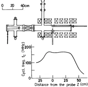
The plasma is produced in the TP-D type device1) . as shown in Fig. 1. which consists of the discharge region and the difiused region of plasma. both regions
* Department of Applied Physics
being connected by the orifice (200 mm in length and 10 mm in diameter) and the pressures of the former and the latter being maintained at about 1.5 x 10⁻² Torr and 7.5 x 10⁻⁴ Torr respectively, by using the method of differential pumping. The plasma is jetted through the orifice from the hole (8 mm in diameter) in the center of anode, flows along the line of magnetic force into the diffused region of plasma, which is made of pyrex glass tube (720 mm in length and 95 mm in diameter) and is ended at the collector of the
same voltage as the anode, and is supported on the axis of the glass tube by the uniform magnetic field whose intensity is 60 gauss (the elec·
tron cyclotron frequency wcl2rc is 168 MHz). The plasma density profile in the radial direction is shown in Fig. 2 (b) and that in the axial direction is uniform within about 5 percent. When the maintenance volt- age of discharge Vd is about 100 volt and discharge current Id is 4.5 rnA, the plasma density np at the center of tube and the electron temperature Te is about 1.5x109 cm-3 and 7.8 eV respectively in diffused region of plasma.
3 Experimental results and discussions
o
IN ~200
.fl00
u >-
u
Fig. 1 The experimental device and the meg·
netic field strength as a function of the axial distance from the exciting antena z.
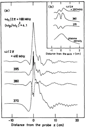
The Bernstein wave is excited by the coaxial antenna inserted radially at the axial position of 390 mm from the anode and detected by two coaxial antennae movable in the radial and axial directions. By using the interferometer system, the propagating wave patterns are drawn on XY recorder as the functions of axial distance z and radial distance r from the exciting antenna, as shown in Fig. 2.
(a) and (b). It must be noted in Fig. 2 (a), that the wavelength in the region of downstream is longer than that of upstream, the both waves being damped rap idly by Landau damping, and the other wave-like signal of shorter 'wavelength' is observed only in the region of downstream. In Table 1. the wave number components along the direction of axis (k II ) and radius (k.L) are calculated from the observed wave patterns, which shows that the observed Bernstein wave pro- pagates at an angle () of about 850 from the line of magnetic force.
In Fig. 3 are shown the dispersion relations of observed Bernstein waves in upstream and downstream, which are slightly different each other due to the Dop- pler effect in streaming plasma. From the difference of phase velocities in the both regions, the streaming velocity Vs of plasma is calculated and shown in Table 1. The result indicates that Vs is 4.1x 108 cm/sec within the observation error of 18
(a)
wc/27C = 168 MHz
(Wp/wc> 2 =4.1
w/21(
o
(b) c.J/27f
~HZ
~ ~
~nlasma
-' ~ty
-1 0
Distance from theaxis r (em)
10 20
Distanct" from tht" probt" z (em)
Fig. 2 (a) The propagating wave patterns as functions of the axial distance from the ex- citing antenna z. The anode is situated at
Z = - 39 cm, so that the plasma is streaming from the left hand side to the right hand side.
(b) The propagating wave patterns and the
"3 -3
>-
Theor. curve (e= 85·)
~ ~ 2~---~~~---~
~ C"
~
C'I .!;
>
.~
cr: ~
.. . . . . I (Wp 1Wc)2 c.JTe=7.8eV c I 2 Tf =
= 168 MHz 4. 1
°0L---~---~----~ 0.5 1.0 Normalized wave number k,,vt/c.Jc
Fig. 3 The dispersion relation calculated from the wave patterns and the theoretical curve for the corresponding experimental conditions.
hollow circle ; Bernstein wave in the region of upstream. larger solid circle ; Bernstein wave in the region of downstream.· smaller solid circle; the wave-like signal with shorter plasma density profile as functions of the 'wavelength' observed only in the region of radial distance from the axis r. downstream.
Table 1 The relation among the frequency (w/27l"), the wave number components (k II' k JJ
and the streaming velocity (Vs ) calculated from the difference of the phase velocities in the regions of up- and down-streams.
w/27l" Vt
k ~ '" wlkll Vs
(MHz) k 1.
-e;;:-
1/ We () = (kB) ( X 10Bcm/s) ( X lOBcm/s)0.181 83.1° 15.13 (upstream)
390 1.50
84.8° 20.60 (downstream) 4.87 0.133
0.144 85.1° 18.62 (upstream)
4.05
380 1. 68
0.100 86.6° 26.71 (downstreaj)
370 1. 70 0.118 86.0° 22.05 (upstream)
3.94 0.087 87.1 ° 29.93 (downstream)
percent. On the other hand, the wave-like signals with shorter 'wavelength' observed only on the downstream are plotted by smaller circles in Fig. 3, which are dis- tributed near the straight line of w/k II = 4.1 X 10⁸ em/sec C = V.). The fact mentioned above does support the consideration that the plasma is streaming with the velocity Vs and the latter wave-like signal may not be the propagating wave but only the modulation of plasma particles floating with the plasma stream.
The theoretical dispersion relation curve corresponding to our experimental conditionsCwNwc2=4.1 and 8=CkB)=85°) is shown with the observed points in Fig. 3 The both results are in good agreement qualitatively. It may be considered that the quantitative disagreement results from the overestimate in electron tem- perature Te observed by the Langmuir probe method, because the plasma is streaming with the velocity Vs
The damping factor C the imaginary part of k II ) was so large that it could not be measured. In conclusion, the Doppler shifted Bernstein wave propagating ob- liquely to the magnetic field is observed in the streaming plasma and its dispersion relation is in agreement with the theoretical curve qualitatively.
Acknowledgement
The authors wish to express their thanks to Mr. I. Kasuga for his kindness to prepare the glass tubes. This work was partially supported by the Grant-in-Aid from the Ministry of Education.
References
1) 1. B. Bernstein Phys. Rev. 109 10 (958).
2) G. Landauer, J. Nuc1. Energy, Pt. C, 4 395 (962); K. Mitani, H. Kubo and S. Tanaka.
J. Phys. Soc. Japan 19 211 (964) ; G. Bekefi. J. D. Coccoli. E. B. Hooper and S. J.
Buchsbaum. Phys. Rev. Letters 9 6 (962) ; c. D. Lustig. Appl. Phys. Lettes 4 194 0 964).
3) M. Seidl and P. Sunka. Nuc1. Fusion 7 237 (967) ; T. Idehara, K. Ohkubo and S. Tanaka, J. Phys. Soc. Japan 27 187 (969) ; B. R. Kusse and A. Bers. Phys. Fluids 13 5372 (1970).
4) E. Canobbio and R. Croci, J. Nuc1. Energy Pt. C. 9 549 (966).
5) J. A. Tataronis and F. W. Crawford, J. Plasma Physics 4 231 (970) and 4 249 (970).
6) S. Gruber and G. Bekefi, Phys. Fluids 11 122 0968 ; F. Leuterer, Plasma Physics 11 615 (969).
7) M. Ohtsuka. K. Takayama et a1.. Proc. 7th Intern. Conf. on Ionization Phnomena in Gases.
Beograde. August 1965.