JAXA Research and Development Memorandum
July 2017
Japan Aerospace Exploration Agency
ISSN 2433-2224 JAXA-RM-17-001E
Path Planning for Rovers on the Moon Based on Shadow Estimation
2
Rover power limitations on the Moon ··· 2
2.1 Power resources available ··· 2
2.2 Amount of generated power ··· 2
2.3 Amount of consumed power ··· 2
3
Shadow estimation on lunar surface ··· 3
3.1 Digital elevation model of lunar terrain ··· 3
3.2 Estimation of shadowed region ··· 3
3.3 Solar elevation and azimuth angles on the Moon ··· 3
4
Path-planning method considering shadow estimation ··· 4
4.1 Path-planning overview ··· 4
4.2 Cost function ··· 5
4.3
Cost function index
4.3.1
C
dist: distance cost ··· 5
4.3.2
C
slope: terrain inclination cost ··· 5
4.3.3
C
shadow: shadow cost ··· 6
5
Path-planning simulation ··· 6
5.1
Evaluation index ··· 6
5.2
Simulation conditions ··· 6
5.3
Simulation results and discussion ··· 6
6
Conclusion ··· 7
Path Planning for Rovers on the Moon Based on Shadow Estimation
Masataku SUTOH*1, Masatsugu OTSUKI*1, Sachiko WAKABAYASHI*1, Takeshi HOSHINO*1
ABSTRACT
In future lunar exploration, mobile robots (i.e., rovers) are required to travel long distances; thus, these rovers will experience severe power limitations. In such exploration missions, the power limitation on the Moon, i.e., the balance between consumed power and that generated by the rover, should be taken into account for motion/path planning. Power generated by solar panels is a possible resource, which is determined depending on the condition of shadows. From this possibility, this study evaluates the influence of these shadows on path planning for lunar rovers by using a proposed path planning method, in which the power limitation is introduced as a new evaluation index. For this evaluation, we developed a path-planning simulator based on a method using digital elevation models (DEMs) derived from Kaguya data. In the simulation, the terrain inclination and shadow on the Moon are estimated by using the DEMs. Using this simulation, path planning is conducted under various insolation (i.e., shadow) conditions corresponding to latitude, longitude, and time for a given terrain. The simulation results show that the power level can be increased in a planned path by considering the influence of the shadow. The effectiveness of the proposed path-planning method is quantitatively confirmed, particularly for an exploration mission conducted in the morning and evening at middle/high latitudes.
Keywords: Lunar rovers, Path-planning, Shadow
1.Introduction
In future lunar and planetary explorations, with the expansion of the exploration area, mobile robots (i.e., rovers) are expected to travel long distances. However, rovers are required to travel efficiently during long-distance travel, but will experience severe power limitations. To this end, it is important to estimate and consider the power consumed and generated by the rover system during such exploration.
Power consumed by rover systems is determined depending on the rover's route; basically, the longer and bumpier the route, the higher the power consumption. Power generated by solar panels is considered as a possible power resource; however, this differs depending on the insolation (i.e., shadow) condition corresponding to the longitude, latitude, and time in a target region. To plan the path of the rover, a comprehensive evaluation index is required, which takes into account these factors regarding consumed and generated power.
Some studies have reported path/motion planning for rovers from the perspective of consumed and generated power. Regarding power consumption, Ishigami et al. conducted a path-planning simulation and evaluated planned paths based on power consumption2,3). Our research group also conducted path-planning simulation for rovers having various locomotion mechanisms, and evaluated these paths based on power consumption 9). Regarding the generated power, Wettergreen et al.13) and Teti et al.10) presented the concept of a sun-synchronous lunar polar rover: the rover continuously remains in sunlight by traveling opposite to the planetary rotation and navigating with the Sun. Thus, the solar panels on the rover can always generate the
necessary power. Tompkins et al. reported a mission planner based on the shadow and position of the Sun 11). In our previous study 9), our research group reported a path-planning simulation conducted under various insolation conditions and evaluated paths based on the amount of generated power. However, we did not extensively discuss the actual available power on the Moon or the balance between the consumed and generated power. Additionally, there are few studies focusing on those topics in terms of path planning.
As mentioned, power generated by solar panels can be determined, depending on the condition of shadows. That is, for discussion on the balance between consumed and generated power, the influence of shadows on path planning should be considered. Thus, in this study, we evaluate the influence of shadows by introducing the power limitation as a new evaluation index for path planning. For this evaluation, we developed a path-planning simulator using digital elevation models (DEMs) derived by using data obtained in a Japanese lunar orbiter mission, Kaguya (SELENE) 5). Using this simulation, path planning is conducted under various insolation (i.e., shadow) conditions corresponding to latitude, longitude, and time for a given terrain.
This paper is organized as follows. Section 2 describes the power limitations on the Moon from the viewpoint of rover systems. Section 3 explains a method for estimating the shadow on the Moon, along with the development of DEMs for the lunar terrain. Section 4 describes a path-planning method considering shadow estimation. Section 5 discusses path-planning simulations conducted under various insolation/shadow conditions. Finally, Section 6 concludes this work.
*
Received April 26, 2017 *1
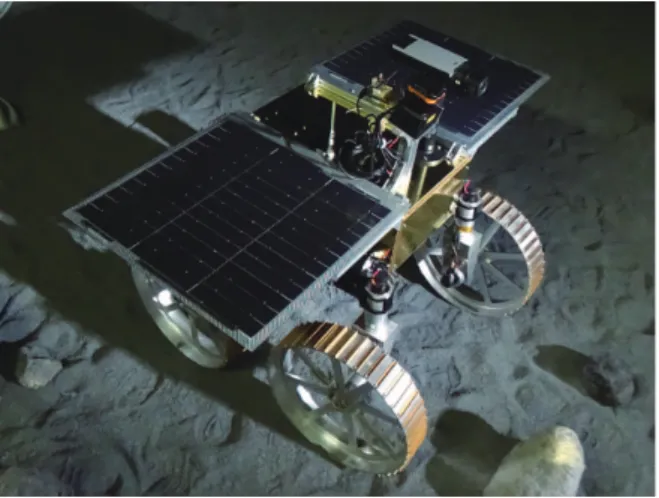
Fig. 1 Lunar rover being developed by our research group at Japan Aerospace Exploration Agency (JAXA).
2.Rover power limitations on the Moon In this section, available power resources are derived by considering on-board battery capacity, power generated by solar panels, and power consumed by the rover's subsystems.
2.1.Power resources available
Storage batteries and power generated by solar panels are considered as possible power resources on the Moon. The power available for a rover, Pava., changes
depending on the power generated by the solar panels and that consumed by various electronic devices on the rover. Thus, Pava. is derived as
Here, Pbat. denotes the capacity of the battery (Wh)
mounted on the rover; PG and PC denote the power
generated by solar panels and that consumed by on-board electronic devices at time t, respectively.
Eq. (1) suggests that if PG is smaller than PC, the
difference between PG and PC is deducted from Pbat..
When Pava. becomes less than 0, the rover can no longer
execute its mission.
2.2.Amount of generated power
In the case that a solar panel is fixed on a rover horizontal to the flat ground, the power generated, PG, by
the solar panel is derived using the solar elevation angle relative to the solar panel, αs’, as
where A denotes the solar panel area; µ denotes the power generation efficiency constant; and I0 denotes the
solar constant. Cs is defined as 0 in a sunlit region and 1
in a shadowed region. Thus, Eq. (2) indicates that the solar panel can only generate power when it is in a sunlit region.
If the solar vector relative to the solar panel is defined
as S' = [x' y' z']T, αs’ is expressed as
If the solar vector, S, defines when the solar panel is horizontal to the flat ground, S' can be derived as
Here, θx, θy, and θz denote the rover's roll, pitch, and yaw
angles, respectively; Rx, Ry, and Rz denote the rotation
matrices around the x-, y-, and z-axes, respectively:
Using the solar elevation angle, αs, and azimuth angle, βs, the solar vector, S, is expressed as
In general, by using Eqs. (2)-(8), the amount of generated power is calculated from the shadow condition, solar angles, and terrain inclination.
By controlling a solar panel to be directed vertically to the sunlight, the generated power can be maximized for a given latitude and time. This control is equivalent to αs
= 90° in Eq. (8). In this study, we assumed that this control strategy is utilized and that the generated power is constant, regardless of the latitude and time. That is, the generated power is considered as a function of shadow condition and terrain inclination.
2.3.Amount of consumed power
The rover system consists of various subsystems, such as spacecraft-bus and mobility systems, as listed in Table 1. In the table, the power consumption of each subsystem is defined as an average value throughout an exploration mission. The table indicates that the characteristics of power consumption differ depending on the subsystems.
In this study, we divide the power consumption, PC, of
the rover into two groups: one determined from the mobility system, PCMov, and the other determined from
the other subsystems, PCothers,. Thus, PC is expressed as
For the subsystem configuration listed in Table 1, PCothers
Path Planning for Rovers on the Moon Based on Shadow Estimation 3
Table 1 Rover subsystem and power consumption
breakdown.
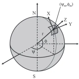
Fig. 2 Lunar coordinate system (ψ, φ, z) and rover coordinate system (X,Y,Z).
The power consumed by the mobility system, PCMov,
changes depending on maneuvers along a traveling path.
PCMov is derived from the power required for driving and
steering maneuvers as
where Vin and I denote the input voltage and current to
the driving/steering motor, respectively. For a mobility system with constant input voltage, Idand Is are derived
by using the climbing slope angle, θy, and steering angle, θs, as
Here, A, B, C, and D are constants determined from the motion behavior of the rover on a given terrain 9). Using Eqs. (10)-(11), the power consumed by the mobility system is calculated from the climbing slope and steering angles in a given terrain.
3.Shadow estimation on lunar surface
As mentioned above, data for the shadow on a given terrain are required to derive the power limitations of the rover. In this section, we first develop DEMs of the lunar terrain by using data obtained in the SELENE project. Subsequently, an estimation method for the shadows on the Moon is explained in detail, along with the solar elevation and azimuth angles.
3.1.Digital elevation model of lunar terrain
We develop DEMs of lunar terrain by using data obtained from Lunar Imager/SpectroMeter (LISM) mounted on the Japanese lunar orbiter SELENE. These
data can be downloaded from the Kaguya data archive 4) as a file containing 4096 × 4096 elevation data for almost all areas of latitude 1° by longitude 1° on the Moon. In the file, the elevation data are obtained in intervals of 7.403 m in latitude.
Using the data from this file, to convert the 4096 × 4096 data set of elevation z[n] for a given lunar coordinate system (ψm, φm) into those for the rover
coordinate system (X, Y, Z), we used the following relationship (see Fig. 2):
Using Eq. (12), the DEM can be developed around any point on the Moon.
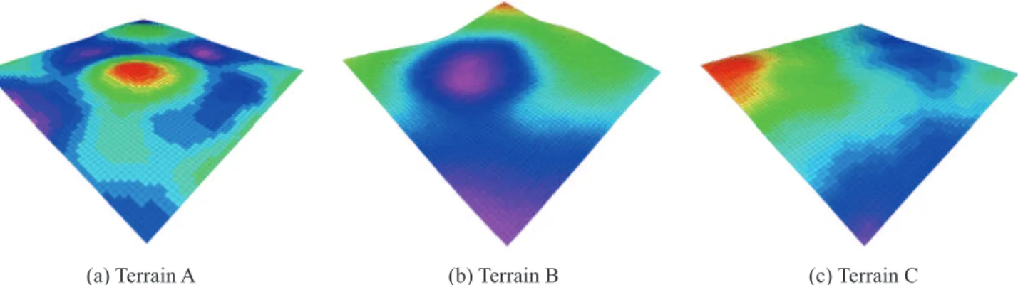
On the basis of this method, we developed three types of DEMs for the lunar terrains, as shown in Fig. 3. The DEMs were developed by using randomly selected data set in low-latitude (0°S, 0°W), middle-latitude (40°S, 0°W), and high-latitude regions (80°S, 0°W), respectively. In the figure, the color represents the differences in the elevation; the elevation increases as the color changes from purple to red. From the changes in color, it is found that the elevation is obtained at high resolution for given areas on the Moon.
3.2.Estimation of shadowed region
For a given terrain, the length and direction of a shadow can be estimated by considering the solar elevation and azimuth angles: the length of a shadow cast by a landform is expressed by using the elevation of the landform, z, and solar elevation angle, αs, as z/tan αs.
Meanwhile, the direction of the shadow is opposite to the solar azimuth angle, βs.
According to the above, a shadow cast by a landform, which is located at point (xp, yp) and has an elevation of
z(xp, yp), is derived as
Here, R is the minimum value that satisfies the following relationship:
Considering Eqs. (13) and (14) over an entire DEM, the shadow is estimated for a given area on the Moon.
3.3.Solar elevation and azimuth angles on the
Moon
The solar elevation angle, αs, and azimuth angle, βs,
Fig. 3 Digital elevation models (DEMs) of various lunar terrains obtained from SELENE data: terrains A, B, and C are derived by using data from low-latitude (0°S, 0°W), middle-latitude (40°S, 0°W), and high-latitude regions (80°S, 0°W), respectively.
Fig. 4 Solar azimuth and elevation angles over a cycle of 29.5 days in various latitude regions: low latitude (0°S, 0°W), middle latitude (40°S, 0°W), and high latitude (80°S, 0°W).
Here, δ and γ denote the latitude and longitude, respectively, on the surface of the Moon where the Sun is directly overhead. δ takes a value between -1.5° and 1.5° because the Moon's rotational axis is almost vertical to the plane containing the Sun. On the other hand, γ changes approximately 12.2° every day. That is, on the Moon, the solar angles roughly change over a cycle of 29.5 days. δ and γ are accurately calculated based on the relative positions of the Sun, Earth, and Moon and the axial tilt of the Moon for a given date 1,8) .
Using Eq. (15), we derived the solar elevation and azimuth angles over a cycle of 29.5 days in various latitude regions, as shown in Fig. 4: low (0°S, 0°W), middle (40°S, 0°W), and high-latitude regions (80°S, 0°W). The figure shows that the elevation angle dramatically changed and the culmination altitude was
high in the low-latitude region. On the other hand, in the high-latitude region, the elevation angle changed slightly and the culmination altitude was low. This means that even in the same exploration time/period, the shadow condition differs depending on exploration regions.
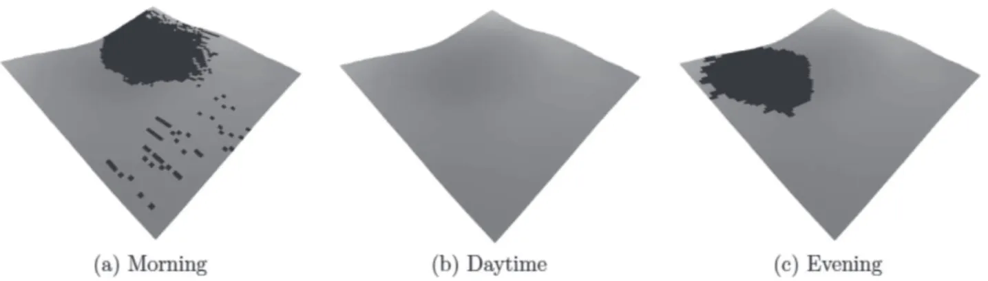
Fig. 5 shows the shadow cast over terrain B, shown in Fig. 3 (b), at different times. The figure shows that the shadow shape changed depending on the time. According to the figure, while the shadow is long in the morning/evening, it disappears during the day. This is because the solar elevation angle is low in the morning/evening and high during the day.
4.Path-planning method considering shadow
estimation
On the basis of the shadow estimation presented in the previous section, we propose a path-planning method for rovers considering the estimation of shadows. In this section, the path-planning algorithm and cost functions are described in detail.
4.1.Path-planning overview
A grid-based path-planning algorithm was adopted to confirm the effectiveness of our proposed method. In this algorithm, the target environment is first divided into an equally spaced grid, and each intersection of the grid lines is labeled as a node. We assumed that a rover can move in eight directions between adjacent nodes (see Fig. 6). In path planning, the start and goal nodes are first identified, and a rover's path is defined by the lines connecting the nodes from the start to goal nodes.
A cost, which is the value for a rover to move from one node to another, is assigned to all edges connecting each pair of nodes. The optimum path for the rover is calculated by minimizing the summation of the cost (i.e., total cost) for the rover to move from the start node to the goal node.
Path Planning for Rovers on the Moon Based on Shadow Estimation 5
Fig. 5 Shadow on the surface of the Moon, on terrain B, under different times (i.e., insolation conditions). (a), (b), and (c) represent the shadow in the morning, daytime, and evening on the Moon, respectively. The figures show the change of the shadow occurring over a cycle of 14 days on the Moon.
Fig. 6 Node ni and its adjacent nodes, nj ; nodes are
defined as the intersections of grid lines. Edges are defined as pairs of nodes 9).
4.2.Cost function
In path planning, the derived path can differ depending on the way the measure of the cost is defined. Thus, the definition of the cost is key to the path-planning method. We derive the cost, c(nij), for an
edge between node ni and adjacent node nj:
where Cdist, Cslope, and Cshadow denote the costs depending
on the distance, terrain inclination, and shadow, respectively; Wdist, Wslope, and Wshadow, are the weighting
factors corresponding to each cost, which are set so that
Wdist + Wslope + Wshadow = 1.
Using Eq. (16), the total cost, C(path), for a path is expressed as
From Eqs. (16) and (17), a decrease in individual cost reduces the total cost. In other words, a path that minimizes Eq. (17) is the optimum path for a rover in
terms of the traveling distance, terrain inclination, and shadow.
4.3.Cost function index
In this subsection, each index in the cost function (i.e., distance cost, Cdist; terrain inclination cost, Cslope; and
shadow cost, Cshadow) is explained in detail.
4.3.1.Cdist: distance cost
If a rover travels a long distance, the necessary power consumption will simply increase. From the viewpoint of energy, the distance along a rover's traveling path should be as short as possible. Thus, we adopted distance as one element to determine the rover's traveling path.
The distance cost, Cdist, for each edge is defined as
follows:
where Dijdenotes the distance between adjacent nodes
and Dmax denotes the maximum Dij for all of the edges.
Dij is derived as follows:
where (xi, yi, zi) and (xj, yj, zj) are the three-dimensional
positions of niand nj, respectively.
4.3.2.Cslope: terrain inclination cost
When a rover traverses/climbs over steep slopes, the wheels of the rover slip and power consumption increases. To decrease the power consumption, the rover should avoid steep crater rims and ridges, and travel along paths with gentle terrain. Thus, terrain inclination (i.e., slope) is considered as another element determining the rover's traveling path.
The terrain inclination cost, Cslope, for each edge is
defined as follows:
where θxij and θyij denote the terrain inclination angles in
the rover's lateral and longitudinal directions (i.e., the rover's roll and pitch angles), respectively; θxmax and
θymax denote the maximum θxij and θyij for all edges in a
three-dimensional information of the DEM.
In the case that a solar panel is fixed on a rover to be directed vertically to the sunlight over flat terrain, which is assumed in this study, the terrain inclination along a path should be as gentle as possible in terms of an increase in the generated power. In this context, Cslope is
an element related not only to the consumed power but also to the generated power.
4.3.3.Cshadow: shadow cost
Although the inclination of a solar panel is one factor determining the power generated, as mentioned previously, the solar panel must be sunlit to behave as a power supply. In other words, to generate power, the rover is required to avoid shadowed areas and allow the Sun to light the solar panel. Thus, the shadow is considered as the other element determining the rover's traveling path.
The shadow cost, Cshadow, for each edge is defined as
follows:
Here, SP stands for solar panel. We determine whether the solar panel is sunlit/shadowed on nj on the basis of
shadow estimation by using the three-dimensional information and the solar angles in the target environment, as explained in the previous section. The solar panels on the rover are usually elevated off the surface and will not be in shadow from low terrain.
In Eq. (21), defining Cshadow as 0 or 1permits a rover
to travel over shadow. This is acceptable because the rover can use the power of on-board batteries in the shadow and is not always required to travel by generating power. If Cshadow were defined as 0 or ∞
depending on the condition of the shadow, which is a popular definition method used in various path-planning algorithms 6), the proposed path-planning method would always let a rover avoid the shadowed area. In this case, however, a path may not be derived in a region mostly covered with shadows (e.g., high-latitude regions on the Moon where the sunlight comes from a nearly horizontal direction, as shown in Fig. 4).
5.Path-planning simulation
On the basis of the above path-planning method, we developed a path-planning simulator for lunar rovers. In this simulator, the power limitation is considered as an evaluation index. In this section, we first derive the power level as an evaluation index, then explain the simulation condition and results in detail.
5.1.Evaluation index
From the viewpoint of power limitations on the Moon,
the power level, Pava., over a path is defined as an
evaluation index for path planning. After a rover traveled over a path, the remaining Pava. is expressed as
where PGij and PCij denote the power generation and
consumption between adjacent nodes, respectively, and are calculated by using Eq. (2) and (9), respectively.
tij.denotes the time required to travel the distance
between adjacent nodes and is derived by using the slip ratio, s, and slip angle, β:
where v denotes the input linear speed of the rover. Here,
s and β are estimated based on the terrain inclination angles (i.e., θx and θy), as previously reported 9,12).
5.2.Simulation conditions
Path-planning simulations were conducted on three types of DEMs shown in Fig. 3 under different insolation conditions. In the simulations, three different times were used: morning, daytime, and evening. The weighting factors in Eq. (16) were set to Wdist = 0.8,
Wslope = 0.1, and Wshadow = 0.1 for path A and to Wdist =
0.1, Wslope = 0.1, and Wshadow = 0.8 for path B. The input
speed of the rover and voltage were set to 1.4 cm/s and 10 V, respectively.
For the power conditions in the simulation, the rover is equipped with four batteries of 120 Wh/kg capacity and a solar panel having an area of 800 mm × 500 mm. The battery capacity was assumed based on the energy density of a general space-hardened rechargeable battery. We assumed that the inclination of the solar panel is actively controlled so that the generated power is constant, regardless of latitude and time. The power generation efficiency constant, µ, and solar constant, I0,
were set to 0.15 and 1368 W/m2, respectively, corresponding to the conditions on the Moon 13). The characteristics of the rover power consumption are listed in Table 1.
5.3.Simulation results and discussion
Path Planning for Rovers on the Moon Based on Shadow Estimation 7
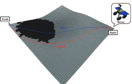
Fig. 7 Simulated paths for rover on terrain B under the insolation condition of the evening; the blue and red lines
represent path A (Wdist = 0.8, Wslope = 0.1, Wshadow = 0.1) and path B (Wdist = 0.1, Wslope = 0.1, Wshadow = 0.8), respectively.
For each path shown in Fig. 7, histories of the power consumed, power generated, and power level were obtained along with time, as shown in Fig. 8. Fig. 8 (a) shows that there is a slight difference in the power consumed by the rover on each path. This suggests that the power consumed by the mobility system (PcMov.) was
almost the same along each path. In Fig. 8 (b), although the rover generates power almost all the way along path B, it cannot generate power at all from 8 h to 14 h, when the rover travels in shadow along path A. As a result, although the power level remains high along path B, it gradually decreases to 82 Wh at the end along path A (see Fig. 8 (c)).
From the simulation conducted on terrain B under different insolation conditions, the traveling time, average power consumption, and average power generation were derived, as shown in Fig. 9. According to Fig. 9 (a), traveling time was longer along path B than path A. This is because the rover avoids the shadow and travels a longer distance along path B. In Figs. 9 (b) and (c), although there is a slight difference in the average power consumption on each path in all cases, the average power generated along path B is greater than that along path A, particularly in the morning and evening; along path A, the large difference between the average consumed and generated power is deducted from the power level. From the viewpoint of power, path B was more energy efficient than path A.
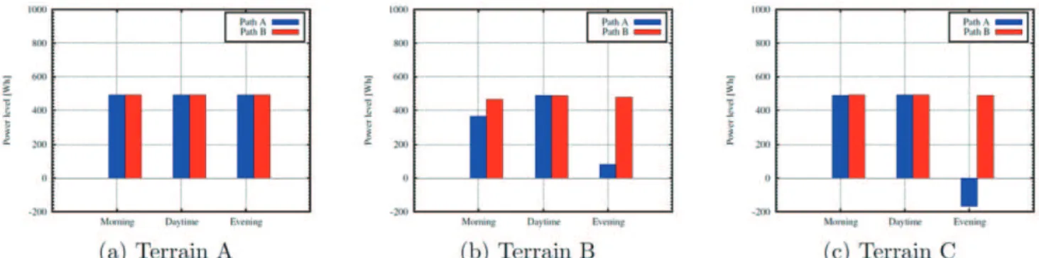
By conducting the simulation on the three types of DEMs shown in Fig. 3 under different insolation conditions, the power levels of the rover were obtained, as shown in Fig. 10. According to Fig. 10 (a), for all times, there is a slight difference in the value of power level along each path in the low-latitude region. This is because the solar elevation is high and the shadowed area is small in this region. Meanwhile, in the middle- and high-latitude regions where solar elevation is low and the shadowed area is large, the power level along path B is larger than that along path A, particularly in the
morning and evening. It is noteworthy that along path A, the power level reaches less than 0 on terrain C in the evening; that is, the rover completely stopped moving along this path. This simulation study quantitatively suggested that the proposed path planning method is effective, particularly for an exploration mission conducted in the morning and evening at middle/high latitudes.
In our path-planning method, the cost function derives different paths depending on the weighting factors in Eq. (16). In this study, to clearly present the influence of the shadow on path planning, we compared the simulation results by using two combinations of weighting factors (Wdist, Wslope, Wshadow): path A with (0.8, 0.1, 0.1) and
path B with (0.1, 0.1, 0.8). We discovered that if the terrain inclination is weighted (Wdist, Wslope, Wshadow) =
(0.1, 0.8, 0.1), the path is derived as similar to that weighted in the shadow, although the former path is not as energy efficient as the latter. During an exploration mission, weights for path planning should be determined on a case-by-case basis. An effective method for determining the weights of various situations in the mission may be an interesting topic for future study.
6.Conclusion
Fig. 9 Traveling time, average power consumption, and average power generation on terrain B under various insolation conditions.
Fig. 10 Power level remaining on various terrains under different insolation conditions. Terrains A, B, and C are derived by using data in low- (0°S, 0°W), middle- (40°S, 0°W), and high-latitude regions (80°S, 0°W), respectively.
Fig. 8 Histories of power consumption, power generation, and power level along with time on terrain B under the
insolation condition of evening: path A (Wdist = 0.8, Wslope = 0.1, Wshadow = 0.1) and path B (Wdist = 0.1,Wslope = 0.1, Wshadow = 0.8).
During the simulation case study, the amount of consumed and generated power were tentatively assumed rather than derived from detailed specifications of a rover. In the future, after defining these factors from actual mission requirements, the path-planning method proposed in this study can be used as an effective tool to optimize the mission and/or to determine whether a planned exploration mission is realistic.
REFERENCE
[1] Acton, Charles H, “Ancillary data services of NASA's Navigation and Ancillary Information Facility”, Planetary and Space Science, Vol.44, No. 1, pp.65—70, 1996.
[2] Ishigami, Genya and Nagatani, Keiji and Yoshida,
Kazuya, “Path planning for planetary exploration rovers and its evaluation based on wheel”, Proc. IEEE Int. Conf. on Robotics and Automation Conference, Roma, Italy, pp. 2361—2366, 2007. [3] Ishigami, Genya and Nagatani, Keiji and Yoshida,
Kazuya, “Path planning and evaluation for planetary rovers based on dynamic mobility index”, Proc. IEEE/RSJ Int. Conf. on Intelligent Robots and Systems, San Francisco, California, USA, pp. 601—606, 2011.
[4] Kaguya Data Archive,
http://l2db.selene.darts.isas.jaxa.jp/index.html.en, accessed February 1, 2015.
Path Planning for Rovers on the Moon Based on Shadow Estimation 9
http://www.selene.jaxa.jp/index_e.htm, accessed February 1, 2015.
[6] LaValle, Steven M, “Planning algorithms”, Cambridge university press, Cambridge, England, 2006.
[7] Nishida, Shinichiro and Wakabayashi, Sachiko, “A System Study of Lunar Surface Exploration Robot”, Proc. of 52nd Space Sciences and Technology Conference, Hyogo, Japan, 2008. [8] SPICE Toolkit,
http://naif.jpl.nasa.gov/naif/toolkit.html, accessed February 1, 2015.
[9] Sutoh, Masataku and Otsuki, Masatsugu and Wakabayashi, Sachiko and Hoshino. Takeshi and Hashimoto, Tatsuaki, “The right path: comprehensive path planning for lunar exploration rovers”, IEEE Robotics & Automation Magazine, Vol. 22, No.1, pp. 22-33, 2015.
[10] Teti, Frank and Whittaker, William and Kherat, Sam and Barfoot, Timothy and Sallaberger, Christian, “Sun-synchronous lunar polar rover as a first step to return to the moon”, Proc. of Int. Symp. on Artificial Intelligence for Robotics and Automation in Space, Munich, Germany, pp. 5—9, 2005.
[11] Tompkins, Paul and Stentz, Tony and Whittaker, William, “Automated surface mission planning considering terrain, shadows, resources and time”, Proc. Int. Symp. on Artificial Intelligence for Robotics and Automation in Space, Montreal, Canada, 2001.
[12] Wakabayashi, Sachiko and Sato, Hitoshi and Nishida, Shinichiro, “Design and mobility evaluation of tracked lunar vehicle”, Journal of Terramechanics, Vol. 46, No. 3, pp.105—114, 2009.
[13] Wettergreen, David and Shamah, Benjamin and Tompkins, Paul and Whittaker, William, “Robotic planetary exploration by sun-synchronous navigation”, Proc. Int. Symp. on Artificial Intelligence for Robotics and Automation in Space, Montreal, Canada, 2001.
平成 年 月 日受付 、
7-44-1 Jindaiji-higashimachi, Chofu-shi, Tokyo 182-8522 Japan URL: http://www.jaxa.jp/
Date of Issue: July 28, 2017
Produced by: Matsueda Printing Inc.
©2017 JAXA