Effect of Blowdown Wind Tunnel Inlet on
the Mainstream Turbulence Intensity
Ayumu Inagaki1*, Daichi Ishii1, Toyohisa Asaji2, Tsubasa Nakamura3, Naoto Watanabe4, Takashi Kikuchi4, Kazumasa Takahashi5
1) Department of Mechanical Engineering, National Institute of Technology (KOSEN), Oita College, 1666 Maki, Oita 870-0152, Japan
2) Department of Mechanical Engineering, National Institute of Technology (KOSEN), Toyama College, 13 Hongo-machi, Toyama 939-8630, Japan
3) Department of Electronic-Mechanical Engineering, National Institute of Technology (KOSEN), Oshima College, 1091-1, Komatsu, Suo-Oshima, Yamaguchi 742-2193, Japan
4) Department of Nuclear System Safety Engineering, Nagaoka University of Technology, 1603-1 Kamitomioka-machi, Nagaoka 940-2188, Japan
5) Department of Electrical, Electronics and Information Engineering,
Nagaoka University of Technology, 1603-1 Kamitomioka-machi, Nagaoka 940-2188, Japan *E-mail: [email protected]
It is well known that the mainstream turbulence intensity in wind tunnel experiments affects flow transition and separation. To reduce this intensity, wind tunnel straightening conditions have been examined in the past. However, these conditions did not reduce the turbulence intensity of the blowdown wind tunnel in our laboratory, because the turbulence from the dustproofing device at the air inlet of the fan is not straightened, even if it passes through the straightening section of the wind tunnel. In this research, the relationship between the mainstream turbulence intensity and the dustproofing device is investigated.
In the experiment, two types of mesh and four types of dustproof felt with different resistance values are installed on the air inlet of the fan. The mainstream velocity and turbulence intensity values are calculated from the fluctuation velocity measured by the hot-wire anemometer at the center of the wind tunnel exit. The mainstream velocity is adjusted by changing the fan-inverter frequency from 0 to 60 Hz. Although it depends on the air-inlet condition of the fan, the mainstream velocity is approximately 0 to 25 m/s.
The mainstream velocity is found to be related to the resistance coefficient of the wire meshes and felts. However, no difference in turbulence intensity due to the resistance coefficient can be observed, and resistance coefficients above a certain level are considered to affect the turbulence intensity. The important point of the wind tunnel inlet conditions is considered to ensure the required inflow rate for the fan, even with the filter attached.
1. Introduction
Aerodynamic characteristics are important factors affecting the performance of windmills, airplanes, trains, and other machines. Wind tunnel experiments are performed when measurement with real objects and conditions is difficult. It is important to consider wind tunnel performance when conducting experiments. With recent advances in science and technology, wind tunnels require better performance than ever before.
Wind tunnels are said to offer good performance if the velocity distribution is uniform with no swirl component, the turbulence intensity is as low and as uniform as possible, and the wind tunnel has low noise and low vibration [1]. Besides this, it is known that mainstream turbulence intensity in the wind tunnel affects flow transition and separation [2]. The conditions for achieving good wind tunnel performance have been reported [3-5]. As an example, Bradshaw and Pankhurst showed the
design of a low-speed wind tunnel comprising fans, diffusers, wire meshes and honeycombs, and contractions [3]. To straighten the wind tunnel, the open-area ratio of the wire mesh must be 57% or more and the honeycomb needs a length of at least six to eight times the cell diameter. It has been reported that the wire mesh has the effect of reducing turbulence fluctuations and that the honeycomb has the effect of removing the swirl and lateral mean velocity variations.
The wire mesh is important for reducing mainstream turbulence fluctuations. Groth and Johansson investigated turbulence reduction by a standard plain-weave wire mesh [6]. It was found that the initial attenuation of the wake near the wire mesh is determined by the mesh width and that the turbulence reduction is not affected by pressure drops. On the other hand, the wire grid of a cylindrical grid and square grid increase mainstream turbulence fluctuations [7]. In addition, the fractal grid induces stronger turbulence [8]. Depending upon the structure of the wire, the characteristics of the flow structure have differed in terms of straightening or turbulence. Although the flow structure associated with each wire structure has been investigated, the direct causes of straightening and turbulence are not understood [9, 10].
In the wire mesh of the wind tunnel’s straightening section, the wire diameter is designed to keep the Reynolds number below 40. To this end, larger wire mesh numbers are better, and should be greater than 10 [4]. The mesh number, as defined by the number of openings in the mesh per inch, is recommended to be from 16 to 32 [5]. By contrast, Kohama stated that a mesh number of five was optimal, and that higher values degrade the wind tunnel performance [1]. It appears that each wind tunnel has its own optimal conditions.
However, in the wind tunnel of our laboratory, the turbulence intensity did not decrease even when the conditions for achieving good wind tunnel performance were satisfied. To improve the turbulence intensity, the cause of the turbulence was investigated. It was found that the turbulence from the dustproofing device at the fan’s air inlet was not straightened, even when it satisfied the conditions for the straightening section. This turbulence of the dustproofing device remains even when stirred by the fan. The dustproofing device cannot be removed, making it necessary to prevent foreign matter from being sucked into the suction port and clogging the straightening wire mesh. In this research, we investigate the relationship between the turbulence intensity of the mainstream and the fan’s dustproofing device.
2. Experimental apparatus
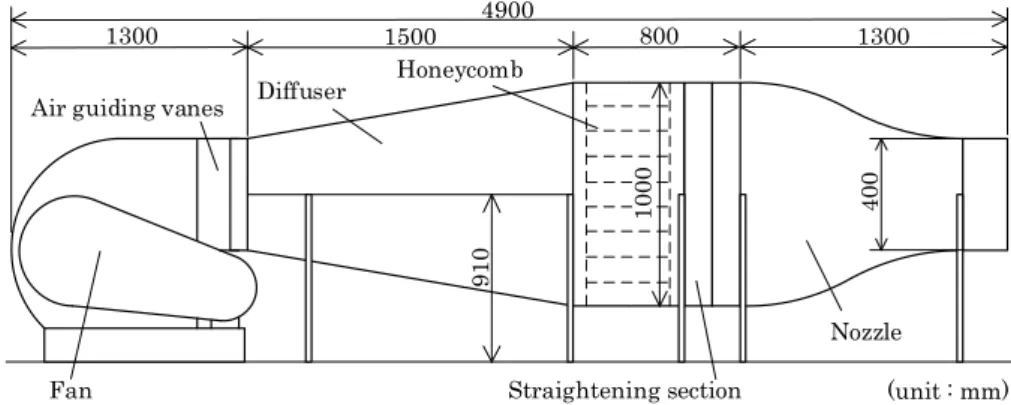
In the experiments, a blowdown wind tunnel with a test section 400 mm high and 400 mm wide is used. An overall view of the wind tunnel is shown in Fig. 1. The wind tunnel consists of a fan, air-guiding vanes, a diffuser, a straightening section, and a nozzle. The air-air-guiding vanes are installed vertically and horizontally to remove the air bias of the fan.
The straightening section consists of a honeycomb and wire meshes. The honeycomb has a cell width of 20 mm and a flow-direction length of 400 mm. The wire mesh satisfies the straightening conditions [3-5]. The wire meshes are installed at four locations: the diffuser inlet, the honeycomb inlet and outlet, and the nozzle inlet. The mesh at the diffuser inlet has a wire diameter of 0.34 mm
Fig. 1 Overall view of the blowdown wind tunnel
Fan 91 0 40 0 (unit : mm) Nozzle 10 00 1300 800 1500 1300 4900
Air guiding vanes Diffuser
Straightening section Honeycomb
Table 1 Types of wire meshes
Mesh Wire diameter (mm) Mesh number Open area ratio (%) Resistance coefficient K
A 0.75 5 72.6 0.11
B 0.25 20 64.5 0.18
Table 2 Types of felts
Felt Felt type Thickness (mm) Resistance coefficient K
a non-woven fabric for gardening 1 0.55
b non-woven fabric for fan filter 2 0.31
c non-woven fabric for fan filter 5 0.66
d non-woven fabric for fan filter 10 0.76
and an open-area ratio of 66.0%, the honeycomb inlet and outlet have a wire diameter of 0.34 mm and an open-area ratio of 61.8%, and the nozzle inlet has a wire diameter of 0.14 mm and an open-area ratio of 60.8%.
The mainstream turbulence intensity is investigated under changes to the mesh at the fan inlet. Two types of wire mesh in Table 1 and four types of felt in Table 2 are attached to the fan inlet, respectively. The mesh A has been used in a wind tunnel fan before now, and mesh B satisfies the same mesh conditions as the straightening section at the air-inlet parameter [3-5]. Felt a is a non-woven fabric for gardening; it is used because it could cover the expansion frame in the experiment of the optimal condition of the air inlet of section 3.2. Felts b–d are non-woven fabrics for fans with different thicknesses. The resistance coefficients K listed in Tables 1 and 2 are calculated from the results of pressure gradients measured in a blow down wind tunnel with a 100 mm high and 100 mm wide duct as a preliminary experiment. In a preliminary experiment, the pressure drop when a dustproofing device was installed at the duct outlet was measured.
Measurements of the fluctuation velocity u for the 400 mm × 400 mm wind tunnel exit are performed using an I-type hot-wire anemometer at each inlet condition. The sampling frequency of the fluctuation velocity is 10 kHz, and the total number of measurement datapoints is 70,000 for a measurement of T = 7 seconds. The mainstream velocity Uaveis calculated from the average fluctuation velocity u. The turbulence intensity Urmsis calculated from the standard deviation of the fluctuation velocity u in Eq. (1):
ܷ௦= ට்ଵ∫ ݑ(ݐ)் ଶ݀ݐ. (1)
This experiment evaluated only the turbulence intensity of the mainstream component u. The mainstream velocity Uaveat the wind tunnel exit is set by changing the motor-inverter frequency from 0 to 60 Hz. Although it depends upon the fan-inlet conditions, the mainstream velocity is approximately 0–25 m/s. Since uniformity around the center of the wind tunnel exit is secured, the measurement position of the fluctuation velocity is set at the center of the wind tunnel exit.
3. Results and Discussion 3.1. Effect of the fan air inlet device
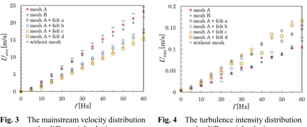
Figure 2 shows the experimental apparatus of the fan air inlet device. The mainstream velocity Uaveand the turbulence intensity Urmsby changing the air inlet device of the fan are shown in Fig. 3 and Fig. 4. The point to note is that the felt cannot be installed alone at the fan inlet, the felt is installed together with wire mesh A.
As shown in Fig. 3, the mainstream velocity increases along with frequency under all fan-inlet conditions. The mainstream velocity with a wire mesh is faster than that with the felts. That without
Fig. 2 Schematic view of the fan air-inlet device
the wire mesh is fastest, reaching about Uave 25 m/s at 60 Hz. On the other hand, the mainstream velocities with the felts are about Uave = 15 m/s at 60 Hz. The mainstream velocity of the wire mesh and felt is related to the resistance coefficient K. It is consistent with fluid-dynamics theory that the mainstream velocity is lower in air-inlet devices with large values of K.
The turbulence intensity result in Fig. 4 shows that the intensity increases with increasing motor-inverter frequency of the fan, just as did the mainstream velocity shown in Fig. 3. The turbulence intensity with the wire meshes is lower than that with the felts; however, the difference in turbulence intensity due to the resistance coefficient cannot be observed. The turbulence intensities of the wire meshes are almost the same between meshes A and B, regardless of the resistance coefficient. Above a certain level, the resistance coefficient is considered to affect the turbulence intensity. However, the turbulence intensity above a certain level, no difference in resistance is seen again. In the next section, a method for reducing the turbulence intensity after attaching the felt at the air inlet is examined.
The distribution of relative turbulence intensity Urms/Uave is shown in Fig. 5. The relative turbulence intensity shows a high value in the slow region, where the mainstream velocity is below 20 Hz about Uave = 5 m/s. Under 20 Hz, the relative turbulence intensity differs between meshes A and B, although the mainstream velocity in Fig. 3 and the turbulence intensity in Fig. 4 are almost the same. The difference in relative turbulence intensity is thought to originate from the slight fluctuation in the turbulence intensity of mesh B in Fig. 4 being amplified by the slow-flow velocity. On the other hand, it shows the constant value of the relative turbulence intensity in the frequency range from 20 to 60 Hz more than Uave = 5 m/s, and the wind tunnel performance can be said to be stable. This stability range is the experimentally testable range of this wind tunnel.
Fig. 3 The mainstream velocity distribution
Fig. 5 The distribution of relative turbulence intensity to mainstream velocity
In the stable range of the wind tunnel at 20-60 Hz, the relative turbulence intensity of the mesh A and mesh B are about Urms/Uave 0.4%. The relative turbulence intensity of the felts is about Urms/Uave 1%. One of the indicators of a low-turbulence wind tunnel is to reduce the relative turbulence intensity value to 0.3% or less [11]. The wind tunnel in this experiment does not reach less than 0.3% indicative of a low-turbulence wind tunnel. However, to investigate the optimal conditions for the air inlet, the values of mesh A are used as target values. In order to reduce the turbulence intensity in this wind tunnel to less than 0.4%, it is necessary to review the conditions of the wind tunnel straightening section.
3.2. Optimal condition of the air inlet
The influence of differences in the suction-flow rate arising from resistance upon the turbulence intensity is investigated, together with the optimal installation conditions for the dustproofing device at the fan inlet. To widen the suction cross section and increase the suction-flow rate, a framework that extends 900 mm in the y-axis direction was installed at the air inlet in Fig. 6. In this framework, felt a or polypropylene boards were placed on the sides and top for comparison. The mainstream velocity and the turbulence intensity are compared under each condition. The wire mesh A is attached to the fan inlet.
The mainstream velocity and turbulence intensity results when space is secured in the air inlet of the fan are shown in Figs. 7 and 8, respectively. The values for mesh A are also shown for comparison. The mainstream velocity and the turbulence intensity increase along with frequency under all conditions, as in Figs. 3 and 4. As for the values, when the side is the polypropylene board and the top is felt a, the mainstream velocity decreases and the turbulence intensity fluctuates. There is no difference in values except in this case.
The relative turbulence intensity result based on wire mesh A is shown in Fig 9. It can be seen that only the case with the polypropylene board side and a felt top exhibit fluctuation, as with the turbulence intensity in Fig. 8. Under other conditions, the flow velocity distributions are the same as the value of wire mesh A, whose frequency is 15 Hz or more. The polypropylene board side and felt on top, however, simply increasing the distance from the air inlet to the felt does not improve the turbulence intensity. Rather, the extension of the air inlet by the wall is thought to increase suction resistance. We speculate that the increase in suction resistance may increase the turbulence intensity by not securing the suction flow required by the fan.
Therefore, the optimal air-inlet condition is to coat the side of the extended inlet in felt. It is found that, even when the dustproofing device is attached, a turbulence strength equivalent to that of the wire mesh alone can be secured. It does not matter whether the top is polypropylene board or coated in felt a. In conclusion, when the inlet area is much larger than the cross-sectional area of the fan air inlet (in this case, when the inlet diameter is 600 mm), the mainstream velocity and turbulent flow strength are not affected by the dustproofing device.
Fig. 7 The mainstream velocity distribution
under different inlet conditions Fig. 8 The turbulence intensity distribution under different inlet conditions
Fig. 9 The relative turbulence intensity between wire mesh A and each types
4. Conclusion
In this study, we investigated the relationship between mainstream-turbulence intensity and the dustproofing device used for the fan of a blowdown wind tunnel. Four types of felt were compared in dustproofing devices, and the optimum installation conditions of the device at the air inlet of the fan were examined. The mainstream velocity is adjusted by changing the frequency of the fan inverter from 0 to 60 Hz, corresponding to a range of about 0 to 25 m/s. The following results were obtained.
The mainstream velocity is related to the resistance coefficient of the wire meshes and felts. However, the turbulence intensity difference due to the resistance coefficient of the felts cannot be observed, and the resistance coefficient above a certain level is considered to affect the turbulence intensity. The wind tunnel inlet conditions are important to consider to ensure the inflow rate required for the fan, even with the filter attached. The consideration in this research is that the mainstream velocity and turbulence intensity are not affected by the dustproofing device when the felt mounting area is much larger than the cross-sectional area of the fan air inlet.
Acknowledgments
This research was supported in part by grant from Nagaoka University of Technology (NUT) grant for collaborative research with National Institute of Technology (NIT).
References
[1] Y. Kohama, “Optimum Screens for Turbulence Reduction in Wind Tunnels,” JSFM, vol. 9, no. 1, pp. 19-33, Jan. 1990.(In Japanese)
[2] M. Yamagishi and S. Tashiro, “Effect of External Fluctuation Frequency Introduced in the Mean-Flow on the Characteristic Frequency of Separated Mean-Flow,” JSME Series B, vol. 45, no. 4, pp. 796-803, Jun. 2002.
[3] P.Bradshaw and R. C. Pankhurst, “The Design of Low-Speed Wind Tunnels,” Prog. Aerosp.
Sci., vol. 5, pp. 1-69,1964.
[4] I. Tani, Y. Kobayashi and H. Sato, “Fluid dynamics experimental method,” Iwanami Shoten
Pub., pp. 14-36,1964. (In Japanese)
[5] The Japan Society of Fluid Mechanics, “Fluid Mechanics Handbook,” Maruzen Pub., pp. 1171-1177,1998. (In Japanese)
[6] J.Groth and A. V. Johansson, “Turbulence reduction by screens,” J. Fluid Mech.,vol. 197, pp. 139-155, May1988.
[7] T. Kitamura et al.,“On invariants in grid turbulence at moderate Reynolds numbers,” J. Fluid
Mech., vol. 738, pp. 378-406,Nov. 2013.
[8] D. Hurst and J. C. Vassilicos, “Scalings and decay of fractal-generated turbulence,” Phys.
Fluids., vol. 19, pp. 1-31,Mar. 2007.
[9] B. G.de Bray, “Some Investigations into the Spanwise Non-Uniformity of Nominally Two-Dimensional Incompressible Boundary Layers Downstream of Gauze Screens,” A. R. C.
Report, No. 3578,pp. 1-18,Jul. 1969.
[10] H. Suzuki et al., “Wind Tunnel Experiments on the Spatial Development of Fractal-Grid Turbulence” JSME Series B, vol. 79, no. 798, pp. 115-125, Feb. 2013. (In Japanese)
[11] S. Fujita and G. Ueno,“Design and Manufacture of Low Speed Wind Tunnel,” Research
reports of the Tokuyama Technical College., vol. 7, pp. 27-31, Dec. 1983. (In Japanese) (Received: 17 December 2019, Accepted: 6 June 2020)