-i-
Contents
Abstract in English ...iii
Abstract in Japanese ... v
Acknowledgement ... vii
List of figures ... ix
List of tables ...xiii
Chapter 1 Introduction ... 1
1.1 Feeding parts ... 3
1.2 MEMS based feeding microparts ... 5
1.3 Feeding micropart by asymmetry ... 9
Chapter 2 Experimental Systems ... 11
2.1 Microparts feeders ... 12
2.2 Microparts movement measurement tool ... 15
2.3 Analysis of microparts movement using particle tracking velocimetry (PTV) ... 17
2.3.1 Canny Edge Detector ... 17
2.3.2 Otsu Thresholding ... 19
2.3.3 Comparison between Canny and Otsu techniques in PTV method ... 20
2.4 Characteristic of Obtained Surfaces by Technologies Fabrications ... 22
2.4.1 Fabricated surface by dicing saw ... 22
2.4.2 Fabricated surface by grinding process ... 24
2.4.3 Fabricated surface by femtosecond laser process ... 25
2.4.4 Fabricated surface by etching process ... 26
2.5 Closing remarks ... 29
Chapter 3 Principle of Unidirectional Feeding... 31
3.1 Introduction ... 32
3.2 Microparts surface inspection equipment ... 32
3.3 Microparts surface characteristics ... 33
3.4 Contact between microparts and saw-tooth surface ... 38
3.4.1 Slope contact ... 38
3.4.2 Point contact ... 39
3.5 Previous feeding experimental results ... 39
3.6 Closing remarks ... 42
Chapter 4 Effect of Asymmetric Patterned Profile on Feeding Velocity ... 43
4.1 Analysis of real surface profiles using scanning laser microscope system ... 44
4.2 Effect of asymmetric profile on the motion of micropart ... 46
4.2.1 Particle Tracking Velocimetry ... 46
4.2.2 Results ... 48
4.3 Effect of Exciting Frequency on Motion of Microparts ... 52
-ii-
Chapter 5 Effect of Geometry Parameters of Asymmetric Fabricated Surface on
Micropart Feeding ... 57
5.1 Experiment Validation ... 58
5.1.1 Experiment Surface ... 58
5.1.2 Tracking Method ... 61
5.2 Results and Discussion ... 62
5.3 Closing remarks ... 64
Chapter 6 Two-Dimensional Modeling Micropart Feeding on a Saw-tooth Surface with Symmetric Vibration ... 67
6.1 Dynamic model of micropart on the asymmetric fabricated surface ... 68
6.1.1 Micropart surface profile model ... 68
6.1.2 Transition among contact conditions ... 68
6.1.3 Equation of micropart motion ... 71
6.1.4 Driving force ... 72
6.1.5 Surface friction force ... 74
6.1.6 Air Drag ... 78
6.2 Numerical Scheme using Matlab software ... 78
6.3 Comparison of experiments and simulation results ... 80
6.3.1 Comparison of experiments and simulation with the effect roughness of surface ... 80
6.3.2 Comparison of experiments and simulation with effect of air drag... 83
6.3.2.1 Amplitude of the vibrating saw-tooth surface ... 83
6.3.2.2 Response of feeding micropart velocity ... 84
6.4 Closing remarks ... 87
Chapter 7 Concluding Remarks and Future Work ... 89
7.1 Concluding remarks ... 89
7.2 Future work ... 90
7.2.1 Present research related to research plan ... 90
7.2.2 Purpose of proposed research ... 91
-iii-
Abstract
The objective of this thesis is to investigate the dynamic motion of micro-parts such as small electronic devices on symmetrical vibratory saw-tooth patterned surfaces by experiment and simulation, providing the guidelines for the development efficient micro self-assembly systems. This approach depends only upon the contact condition between the feeder surface and the microparts to carry out microparts one direction. So, the driving system is simple and uses an open loop system for feeding.
To move micro-parts in a desired direction is attractive issue since it has wide applications in electronics industry, micro-logistics, and micro-robot industry. In the micro world, friction dominates in the force applied on microparts rather than its inertia due to adhesion and electrostatic force, van der Waal’s force, intermolecular force, and surface tension. However, the effect of these forces on the motion of micro-parts has rarely studied with the variation of the driven system and micro-parts parameters. Therefore, this thesis investigates deeply on the effect of geometry parameters of asymmetric surfaces and microparts, actuator parameters of a feeding system, and environment parameters on the motion of micro-parts by both experiment and simulation techniques. The comparison between experiment and simulation that can model above forces allows identifying the important forces and parameters. Thesis is organized as follows:
Chapter 1 provides a review of the existing micro-feeder systems.
Chapter 2 introduces the available experiment systems as well as demonstrating fabrication technologies of experimental saw-tooth surfaces. In this chapter we also introduce particle tracking velocimetry (PTV) method to track micro-parts position with time.
Chapter 3 describes basic principle of one-directional feeding of micro parts along an asymmetric surface driven by symmetric vibration.
Chapter 4 investigates the effect of the saw-tooth profile of surface and exciting frequencies on the motion of micro-parts by experiment. The obtained results show that
-iv-
micro-parts can move faster on the surfaces which have the patterned profiles closest to the saw-tooth shape.
Chapter 5 studies the effect of relationship between geometry parameters of surfaces and micro-parts on the motion of micro-parts. We found that the velocity profiles of the micro-parts against characteristic velocity of the surface are similar for the same relative length of micro-part to the saw-tooth pitch.
Chapter 6 describes the simulation model of the micro-parts on saw-tooth surfaces. The model includes the effect of surface roughness, relative micro-parts geometry parameters to the surface geometry parameters, adhesion, and environment parameters. The contact between the micro-part and saw-tooth surface is assumed to be at the contact between a number of hemisphere on the micro-part and the surface, resulting in either a point contact or slope contact. The surface roughness is modeled as a random normal vector with a pre-described distribution. The model describes well the motion of micro-parts.
-v-
主 論 文 要 旨
論文内容の要旨 本論文は,のこぎり歯形状を有する非対称表面上のマイクロパーツの運動を, 実験やシミュレーションを通して解析することを目的とする.これにより,マ イクロパーツの効率的な搬送システムの開発を目指す.提案する手法では,フ ィーダ表面とマイクロパーツとの接触状態により,マイクロパーツを一方向に 搬送することができる.したがって,オープンループの単純な機構で搬送を実 現することができる. マイクロパーツを定められた方向に搬送することは,電子産業や精密産業, マイクロロボットなど広い応用を持つ.マイクロパーツの世界では,慣性力よ り摩擦力が支配的であり,凝着力,静電力,ファンデルワース力,分子間力, 表面張力など様々な力が作用する.しかしながら,これらの力がマイクロパー ツの動的な運動においてどのように作用するか,特に搬送システムやマイクロ パーツのパラメータにどのように依存するかは,ほとんど知られていない.そ こで本論文は,非対称表面やマイクロパーツの幾何パラメータ,搬送システム のアクチュエータのパラメータ,さらに雰囲気のパラメータがマイクロパーツ の搬送に与える影響を実験とシミュレーションを通して明らかにする.実験と シミュレーションの結果を比較することにより,マイクロパーツの搬送に支配 的な力やパラメータを見い出す. 本論文の構成を以下に示す. 第 1 章では,既存のマイクロパーツ搬送システムについて述べる. 第 2 章では,実験システムについて述べる.さらに,マイクロパーツの運動 を計測する手法である粒子追跡流速測定法(PTV)について述べる. 第 3 章では,非対称表面上におけるマイクロパーツの搬送の原理を述べる. 第 4 章では,非対称表面の幾何パラメータと表面の駆動周波数がマイクロパ ーツの運動に与える影響を実験的に調べた結果を示す.実験結果より,のこぎ り歯形状に近い表面上で,マイクロパーツは速く運動することがわかった. 第 5 章では,非対称表面とマイクロパーツの幾何パラメータが,マイクロパ ーツの運動に与える影響を述べる.マイクロパーツの搬送速度と表面の速度の 関係が,マイクロパーツの寸法とのこぎり歯のピッチの関係で表されることを 示す. 第 6 章では,のこぎり歯表面上のマイクロパーツの運動のシミュレーション モデルについて述べる.提案するモデルは,表面粗さ,マイクロパーツと表面 の幾何パラメータ,凝着力,雰囲気のパラメータを有する.マイクロパーツと のこぎり歯表面との接触を,パーツの表面を表す有限個の半球と表面との接触 で表す.このとき,個々の半球と表面との接触は,点接触か斜面接触で表され る.表面の法線方向を確率的な分布を有するベクトルで表すことにより,表面 粗さをモデル化する.提案するモデルは,マイクロパーツの運動を良く表現す ることができる. 第 7 章では,結論と今後の課題を述べる-vii-
Acknowledgement
This research was granted by Japanese Government (Monbukagakusho: MEXT) scholarship program.This thesis grew up from the indispensable support of my supervisor professor Shinichi Hirai. I would like to take this opportunity to express my sincerest appreciation to him for his guidance in the completion of my thesis. The sincerest gratitude goes to him for conducting me to microparts feeding, for worthy research discussions. He always encourages us as well as to make creatively working ambience, sufficient convenience for research. Without his assistance and persistent help this thesis would not have been possible.
I would like to acknowledge to Dr. Atsushi Mitani for cooperation with me, and for sharing his model regarding dynamic micropart motion.
I am particularly indebted to Dr. Xuan Thien Dinh for contributing valuable ideas in our work. Many ideas become transparent after conversations with him.
Further I desire to show appreciation to all my colleagues in my own Integrated Machine Intelligence Lab. for the very good atmosphere as well as for the fruitful scientific discussions. They also helped on using computer systems and on discovery Japanese life, but particularly to Ms Hatanaka, a lovely secretary, who help me a lot with purchase of experimental devices, documents.
Lastly, I am grateful to my parents who have given support throughout my life. Without their helps, my achievements had become impossible.
-ix-
List of figures
Figure 1.1 Vibratory Bowl Feeders 4
Figure 1.2 Sensorless parts orienting using programmable force fields: the part reaches unique orientation after two subsequent squeezes. There exist such orientating strategies for all polygonal partsFeeder systems to transport parts in linear direction were also developed (Barnes et al., 1992; Frei et al.
2002). 4
Figure 1.3 Setup for superconducting magnetic levitation, actuation and magnetic
sensing 5
Figure 1.4 General structure of MEMS-based actuator array for air-flow distributed
micromanipulation 6
Figure 1.5 a) Electric field vector W traveling across a dielectric particle with velocity vE and position of the included dipole moment P describing the localization of induced charges (+, -). The force (F) leads to particle motion (v) contrary
to the f 6
Figure 1.6 Feeder using inertial force: Feeder by inertial force. (Left) Simulation of the displacement of the table along the X direction, (Right) photography of the
feeder and his hight voltage piezoelectric actuator 7
Figure 1.7 The sound field in the fluid gap 7
Figure 1.8 Piezoelectric vibratory conveyor 8
Figure 1.9 a) A point fixed to the surface is at xS relative to a fixed point in the world, and the part is at xp. Gravity holds the part to the surface. b) Experimental
setup 9
Figure 1.10 Diagram of a micropart feeder with a saw-toothed surface and symmetric
vibrations 10
Figure 2.1 (a) Microparts feeder system using accumulated piezoelectric actuator, (b)
schematizes the driving system 13
Figure 2.2 (a) Microparts feeder system using a couple bimorph piezoelectric actuators, 14 Figure 2.3 Difference between two systems: accumulated piezoelectric actuator and
bimorph piezoelectric actuator. 14
Figure 2.4 Experiment system: (a) function generator and power amplifier, (b) microscope, (c) feeding system and (d) a typical micropart. 15
-x-
Figure 2.5 (a) The laser microscope system, (b) The microscope system 17 Figure 2.6 Procedure for detecting center of micro – parts: (a) row image, (b) improved
image, (c) edge detection by Canny method, and (d) tracked center. 18 Figure 2.7 Procedure for detecting position and rotation of microparts: (a) raw image,
(b) tracked center. 19
Figure 2.8 a) Original image, b) Edge detection by Otsu technique, c) Edge detection by
Canny technique 21
Figure 2.9 Two types of surface profiles of a silicon wafer. 22
Figure 2.10 A typical diamond blade for saw-tooth process. 23
Figure 2.11 Saw-toothed silicon wafers fabricated by a dicing saw 23 Figure 2.12 Microscopic image of a sawtoothed surface fabricated by a dicing saw with
a bevel type blade: 3D image synthesized from focusing images by height,
and colored contour model 23
Figure 2.13 A grooving blade 24
Figure 2.14 Profile of fabricated surface by grinding process on cemented carbide
material 24
Figure 2.15 Microfabricated surface profile seen in atomic force microscope 25
Figure 2.16 Microfabricated surface periodicity 26
Figure 2.17 Microscopic image of a sawtoothed surface fabricated by the anisotropic
ething process of [221] oriantation silicon wafer 27
Figure 2.18 Remained resist film on thee anisotropic etched process 28 Figure 2.20 3D analysis model of asymmetric etched surface and their sections of three
arbitrary points 29
Figure 3.1 Microscopy raw image of ceramic chip capacitors: (a) 0402-, (b) 0603-, and
(c) 2012- capacitors 33
Figure 3.2 Measurement results 3D contour line of electrode of ceramic chip capacitors:
(a) 0402-, (b) 0603-, and 2012- capacitors 35
Figure 3.3 Measured section of capacitors: (a) 0402-, 0603-, and 2012- capacitors 36
Figure 3.4 Micropart surface model 36
Figure 3.5 Saw-tooth surface model 37
Figure 3.6 Two contacts between a micropart and a saw-tooth 37
Figure 3.7 Diagram of a micropart feeder with a sawtoothed surface and symmetric
-xi-
Figure 3.8 Statics of each contact condition 38
Figure 3.9 Experiment table set up for 2012-capacitors 40
Figure 3.10 Motion of the 2012-type capacitors due to a 10 Hz on a = 300 surface 41 Figure 3.11 Motion of the 2012-type capacitors due to a 15 Hz on a = 300 surface 41 Figure 3.12 Motion of the 2012-type capacitors due to a 30 Hz on a = 300 surface 41 Figure 3.13 Motion of the 2012-type capacitors due to a 15 Hz on a = 600surface 42
Figure 4.1 Ideal saw-tooth profile of surface 44
Figure 4.2 Microphotograph and profile of saw-toothed fabricated surfaces 45 Figure 4.3 Examples experimental tracking center of micropart (a) improved image, (b)
tracking center 48
Figure 4.4 Variation in micropart velocity with time 50
Figure 4.5 Spectrum of x-velocity on brass (a), carbide (b), and zirconia (c) surfaces 51
Figure 4.6 Variations in micropart displacement with time 52
Figure 4.7 Probability distribution of micropart velocity 54
Figure 4.8 The standard deviation of velocity along x-direction at different frequencies 55 Figure 4.9 Displacement along z-direction at different frequencies 55 Figure 5.1 Experimental surfaces and profiles with different saw-tooth pitches, p 59 Figure 5.2 Examples experimental tracking center of microparts, (a) improved image,
(b) tracking center. 61
Figure 5.3 The variation of micropart velocity with analysis feeding microparts for the
same value of ratio l/p = 4 runs with frequencies 63
Figure 5.4 The variation of micropart velocity with analysis feeding microparts for the
same value of ratio l/p = 10 runs with frequencies 63
Figure 5.5 The variation of micropart velocity with analysis feeding microparts for the
same value of ratio l/p = 20 runs with frequencies 64
Figure 5.6 Diagram of individual asymmetrical force on a micropart 64
Figure 6.1 Model of 2012 capacitor 68
Figure 6.2 Contacts of a convexity and two saw-teeth 70
Figure 6.3 Coordinates of micropart transferred from hemispheres 71
Figure 6.4 Pseudo vector field normal to saw-tooth surface 73
-xii-
Figure 6.6 Cross section of the fabricated surface 76
Figure 6.7 Adhesion friction model 77
Figure 6.8 Model of adhesion force on saw-tooth 77
Figure 6.9 Approximate saw-tooth profile; dashed red line represents ideal saw profile; solid black line represents real saw-tooth profile approximated by adding
white noise to ideal profile 78
Figure 6.10 Flow chart for simulation of micropart motion 79
Figure 6.11 Velocity of micropart x-component with respect to time 81
Figure 6.12 Spectrum of velocity along x-direction 81
Figure 6.13 Ensemble averaged displacement of micropart with respect to time 82 Figure 6.14 Ensemble averaged rotation angle of micropart in (x,y) plane 82
Figure 6.15 The experimental amplitude with time at 100 Hz 85
Figure 6.16 The spectrum of x displacement with frequencies at 100 Hz 85
Figure 6.17 The experiment amplitude for range of frequency 86
Figure 6.18 Variation of ensemble average velocity of micropart with frequency for l/p
= 4 86
Figure 6.19 Variation of ensemble average velocity of microparts with frequency for l/p
= 10 87
Figure 7.1 Automatic assembly system in industry 92
Figure 7.2 Development of multiple functional surfaces for microparts feeder with
simple planar symmetric vibration. 92
-xiii-
List of tables
Table 2.1 TDK C-Series Specifications 16
Table 5.1 Relative scale with different saw-tooth pitches 60
1
Chapter 1
Introduction and Related Work
The objective of this thesis is to investigate the motion of microparts on symmetrical vibratory saw-tooth patterned surfaces by experiment and simulation and then, provides the guidelines to develop efficient micro self-assembly systems.
To move microparts in a desired direction is attractive issue since it has wide applications such as electronics industry, micro-logistics, micro-robot industry, and particular self-assembly in micro-world. The term “self-assembly” has been applied for the manufacture of systems incorporating large numbers of micro-devices. The principle to move parts often encompasses vibration in combination with electrostatic, fluidic, and other forces. In the micro world, the force on micropart includes not only inertia but also friction due to adhesion and electrostatic force, van der Waal’s force, intermolecular force, and surface tension (Y. Komari, 1993). However, the effect of these forces on the motion of microparts has rarely studied with the variation of the driven system and microparts parameters. Therefore, this thesis investigates deeply on the effect of geometry parameters, actuator parameters, and environment parameters on the motion of microparts by both experiment and simulation technique. The comparison between experiment and simulation which can model above forces and parameters allows identifying the important forces and parameters. The procedure of this thesis is step by step described in seven chapters as bellow.
Chapter 1 gives a review of the existing micro-feeder systems.
Chapter 2 introduces the available experiment systems in our Robotic Laboratory at Ritsumeikan University and Design Laboratory at Sapporo City University. In this chapter we also introduce particle tracking velocimetry (PTV) method to track microparts position with time.
2
Chapter 4 investigates the effect of the saw-tooth profile of surface and exciting frequencies on the motion of microparts by experiment. The obtained results show that microparts can move better on the surfaces which have the patterned profiles closest to the saw-tooth shape.
Chapter 5 studies the effect of relative microparts geometry to the surface geometry on the motion of microparts. We found that the velocity profiles of the microparts against characteristic velocity of the surface are similar for the same relative length of micropart to the saw-tooth pitch.
Chapter 6 describes the simulation model of the microparts on saw-tooth surfaces. The model includes the effect of surface roughness, relative microparts geometry parameters to the surface geometry parameters, adhesion, and environment parameters. The contact between the micropart and saw-tooth surface is assumed to be the contact between a number of hemisphere on the micropart and the surface, which results in either a point contact or slope contact. The surface roughness is modeled as a random normal vector with a pre-described distribution. The model describes well the motion of microparts.
3
1.1 Feeding parts
Many industrial applications require part feeder to sorting, arranging, and moving a large number of parts automatically to a desired target at a certain time. For example, in automatic assembly, the orientation and position of the parts are important because the parts have to be aligned in a desired orientation before assembly processes (Ngoi et al., 1995).
Moreover, feeder systems using vibratory mechanism can be used to check the cracks and other defects of the parts. Therefore, feeding parts have been widely studied with various principles to feed parts.
The most popular feeder was the vibratory bowl-type which has been found in many applications such as automobile, pharmacy, cosmetics, electronics, fasteners and plastics, to sort and orient parts before assembly (Maul et al., 1997; Okabe et al., 1981; and Morrey et al., 1986) (Fig. 1.1). A typical vibratory bowl feeder consists of a bowl mounted on a base by three or four inclined leaf springs. An electromagnet is placed between the base and bowl. The bowl travels vertically and twists about the vertical axis by the constrain of the springs and the electromagnetic force between the bowl and the electromagnet. Parts are conveyed in the bowl by one of two modes: sliding and hopping. In the sliding mode, the motion of part is produced from friction between the part and the bowl. As the bowl rises and twists forward, the friction between the track and part drives the part forward with the track. When the track descends and twists backward, the friction is lessened, so the part moves less backward. In the hopping mode, part moves forward with the bowl as the bowl rises and twists, but the part falls freely when the bowl moves downward with the acceleration exceeding the gravity.
Levy (2001) studied further on the conveyor feeders by considering mathematical models to evaluate the probability distributions of the natural resting aspects of prismatic parts in a bowl feeder. The models were applied to study the motion of prismatic parts in square, cylindrical, triangular, hexagonal, rectangular, and symmetrical and asymmetrical T shapes. The models were also applied to analyze three different terminal connectors. The analytical results were agreed well with experimental data in the drop test results.
4 Figure 1.1 Vibratory Bowl Feeders
Another conveyor feeder principle relies on the idea of “distributed manipulation” (Bohringer et al., 2000). In this principle, the feeder consists of a large number of simple structure manipulators (Fig. 1.2). Each manipulator is capable to move part to the neighbor. Successively, the part can be transported in a simple and inexpensive way.
Figure 1.2 Sensorless parts orienting using programmable force fields: the part reaches unique orientation after two subsequent squeezes. There exist such orientating strategies for all polygonal partsFeeder systems to transport parts in linear direction were also developed (Barnes
et al., 1992; Frei et al. 2002).
In these feeders, the surfaces were oscillated in two directions: vertical and horizontal directions. The aspect ratio of the horizontal/vertical oscillation amplitude was controlled to prevent the parts from jumping.
5
1.2 MEMS based feeding microparts
Recently, parts to assembly devices have been down scaled into sub-millimeter scale since the devices is required to compact to save consumption energy. Fortunately, with the development of MEMS technology, various principles for micro scaled parts are available such as magnetic, pneumatic, ciliary, and ultrasonic feeder.
Komari et al. (1993) reported a feeder for microparts with an array of linear actuators. The actuators were actuated by superconducting magnetic levitation (Fig. 1.3). The movement of the linear actuators was limited to one direction because almost of the actuators can have linear guides. Later, Iisuka et al. (1994) improved the design of the actuators that allows the actuators moving in two linear directions and rotation. In this design, the stator layer is planar distributed under the slider. This feeder system provides a smooth linear and rotating motion with high resolution.
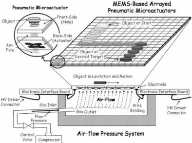
Figure 1.3 Setup for superconducting magnetic levitation, actuation and magnetic sensing In pneumatic feeders, air flows are used to transport microparts. MEMS technology was used to mount on planar board arrays of micro sized nozzles that, by turning on or off air flow, can control the direction of the moving microparts (Konish et al., 1994-1999, Arai et al., 2002). The advantages of this type of feeder are frictionless and large force on the parts. Therefore, various MEMS feeder have been developed. Fukuta et al. (2006) presented a pneumatic feeder composed of an array of micro actuators which can be realized by bulk MEMS technology.
6
Figure 1.4 General structure of MEMS-based actuator array for air-flow distributed micromanipulation
At the top level, the authors found the MEMS layer based on pneumatic microactuator. The second level represents the microsensor layer to detect positions of the object. Finally, all sensor information is addressed and proceeds at the microcontroller level to drive the distributed MEMS surface.
The method of using electric fields for feeding microparts has been discussed numerous literatures (Flix et al., 1999). In G. Fuhr et al. (1995) work, the mechanism to move micro particles was similar to a dielectric induction motor. Depending on the passive electric properties of the particle and the surrounding medium, two cases of polarization could occur (Fig. 1.5 a, b) and consequently the particle moves in or contrary to the direction of electric field motion, respectively.
Figure 1.5 a) Electric field vector W traveling across a dielectric particle with velocity vE and position of the included dipole moment P describing the localization of induced charges (+, -). The force (F) leads to particle motion (v) contrary to the f
7
Paris et al., (2008) presented the concept of the feeding by inertial force. His approach was based on control mechanical vibrations in order to move the microparts. These vibrations allowed breaking adhesion and friction (Fig. 1.6). To control the displacement they have used the Input Shaping technique. After identification of the dynamic behavior of the moving table, the time delays and the amplitudes of impulses have been calculated. The feeder allowed to reduce the residual vibrations and then controlled the acceleration of the feeder.
Figure 1.6 Feeder using inertial force: Feeder by inertial force. (Left) Simulation of the displacement of the table along the X direction, (Right) photography of the feeder and his hight voltage piezoelectric actuator
Another method to transport microparts is using ultrasonic force. The general principle of ultrasonic feeder was explained in detail in (E. Benes et al., 2005, Haake et
al., 2003). A vibrating plane emitted ultrasonic sound that was reflected at another rigid
plane (Fig. 1.7). Depending on the surface movement of the emitting plane, a two- or three-dimensional standing sound field was built up between these two planes. With this sound field, it was possible to position small particles in one or two dimensions and to hold them in an equilibrium position in the vertical direction. By changing the sound field the microparts can be moved.
8
Other systems used the concept of ciliary actuator. Suh et al., (1999) described a first functional ciliary actuator array integrated with CMOS circuitry. The actuator’s tip can deflect and then lift microparts. The overall architecture of the chip and supporting hardware allow moving microparts.
Figure 1.8 Piezoelectric vibratory conveyor
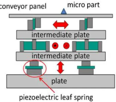
Fleisccher et al., (2011) presented a multi body simulation model describing the micro slide principle including all major influencing parameters for microparts. The model of the feeder included three actuator systems to elevate and transport microparts as shown in Fig. 1.9. Depending on the type of the superimposition of the three oscillations, it was possible to transport micropart on the feeder surface in good agreement with a pre-determined path.
Finally, various feeding system using superconducting (Kim et al., 1989), bimorph piezoelectric actuators (Chang et al., 2000, Ting et al., 2002-2005), and inchworm systems (Zesch et al., 1995, Higuchi et al., 1990, and Codourey et al., 1995) have been developed. Research topics have included the effects of the surface contamination of tracks on feeding (Francisco et al., 1991), traps designed for the alignment (Berretty et
al., 1999), and solutions to models to describe the touching or overlapping parts (Maul et al., 1994).
9
1.3 Feeding micropart by asymmetry
In order to reduce the complex in control of a feeder, asymmetry pattern of the feeder surface or linear vibration of the feeder was considered. There were three pattern asymmetries.
First principle was fast/slow driving of a plane in the horizontal plane in which the asymmetry was time of slipping in one direction versus another to create a net impulse on microparts in one cycle. By using this principle, microparts could move in different directions on the one-degree-of-freedom linear conveyors (Okabe et al. 1985, Umbanhowarp et al., 2008) and a planar shaker plate (Reznik et al. 1998-2011). Okabe
et al. (1985) studied to find a periodic longitudinal waveform of an inclined surface that
maximized the speed of the microparts. They used a finite parameterization of the waveform and conducted numerical simulation to provide the guidelines for the choice of these parameters. Umbanhowarp et al., (2008) incorporated acceleration constraints and solved exactly the optimal driving waveform without parameterization. Consequently, they could drive an optimal feeding motion in both the horizontal and vertical directions.
Figure 1.9 a) A point fixed to the surface is at xS relative to a fixed point in the world, and the part is at xp. Gravity holds the part to the surface. b) Experimental setup
The second principle was similar to the first principle. However, the asymmetric friction force lied on the asymmetric normal force between the microparts and feeder surface in one cycle of the vibration. The vibrating feeder surface was generated the horizontal plane (x-y-yaw) and out of the horizontal plane (z-roll-pitch) (Umbanhowarp
et al., 2008-2012; Boothroyd et al. 2005; and Peter et al., 2000). In this type of feeder,
the asymmetrical normal force arises due to the time-dependent out-of-plane acceleration.
10
The third principle was anisotropic texture of the feeder surface. Mitani et al., (2006-2011) proposed a micropart feeder that has saw-tooth profile texture on the feeder surface. The microparts can move in one direction with simple horizontal sinusoidal oscillation of the feeder (Fig. 1.10). His study was carried out for various saw-tooth geometry parameters and exciting frequencies. They also examined the motion of microparts on different profiles of the asymmetric structure which are achieved by the ability of fabricated technologies. However, his study method was unable to study the dynamics of the microparts. In addition, the results were reported case by case without systematical conclusion.
Figure 1.10 Diagram of a micropart feeder with a saw-toothed surface and symmetric vibrations This thesis will focus on the third principle to move microparts in a desired direction, since this principle is simple and then easily to integrate to a self-autoassembly system. The thesis will systematically investigate the effect of the geometry parameters of the feeder surface, actuator parameters, and environment parameters on the motion of microparts by both experiment and simulation techniques. The experiment technique will be considered in the way that we can observe time-dependent motion and dynamics of the microparts. Simulation technique focuses on the uncertain effects in micro-world such as the effect of the feeder surface roughness no the motion of the microparts.
11
Chapter 2
Experimental Systems
This chapter introduces the experiment system as well as analyzes the microparts movement by using particle tracking velocimetry (PTV) method. In order to drive microparts feeder table, the accumulated piezoelectric actuator and the bimorph piezoelectric actuator are used. Because in the previous relative works, the moving microparts were recorded for a distance and then the micropart velocity was measured as time averaged velocity on this distance. Therefore, it could not observe the dynamic motion of the microparts. In this thesis particle tracking velocimetry (PTV) is used to determine the time-dependent velocity of the microparts. Two techniques, Canny edge detection and Otsu thresholding, to detect the position of the microparts are discussed. Moreover, the technologies to fabricate the saw-tooth surfaces including dicing saw process, grinding process, femtosecond laser process, and etching process are introduced in Section 2.4.
12
2.1
Microparts feeders
The piezoelectric actuator (PZT) is a well-known commercially available device for managing extremely small displacements in the range of 10 pm (1 pm = 10-12 m) to 100 m (Adriaens H,. al et, 2000). A PZT actuator is an electromechanical device that undergoes a dimensional change when voltage is applied. The conversion of electrical energy into mechanical energy takes place without generating any significant magnetic field or need for moving electrical contacts. Dimensional changes are proportional to the applied voltage and can therefore be adjusted with extremely high resolution. PZT actuators can be operated over millions of cycles without wear or deterioration. Their high response speed is limited only by the inertia of the object being moved and the output capability of the electronic driver. Figure 2.1, 2.2 shows photos of the micro – parts feeding system driven by accumulated piezoelectric actuator and bimorph piezoelectric actuators.
Feeder Surface
13
Figure 2.1 (a) Microparts feeder system using accumulated piezoelectric actuator, (b) schematizes the driving system
(b)
14
Figure 2.2 (a) Microparts feeder system using a couple bimorph piezoelectric actuators,
Figure 2.3 Difference between two systems: accumulated piezoelectric actuator and bimorph piezoelectric actuator.
Figure 2.3 shows that the accumulated piezoelectric actuator is good for high frequency but low hysteresis while the bimorph is good for low frequency driving but large hysteresis and bad thermal characteristics.
15
2.2 Microparts movement measurement tool
The experimental feeding system includes a saw – tooth surface attached to a vibratory table, a function generator, an amplifier, and a microscope (VH – Z20R, Keyence), as shown in Fig. 2.4. The microscope is connected to a variable magnification lens, providing a 20 mm 200 mm field of view. The lens is adjustable in three directions and perpendicularly oriented to the saw–tooth surface. The vibratory table is horizontally oscillated by a piezoelectric actuator. The actuator is driven by the function generator through the amplifier, which can supply a square/sinusoidal wave with a peak-to-peak output voltage of up to 300 V.
Figure 2.4(a) shows a typical sample of the C – series ceramic chip capacitors (TDK Inc.), which is used as the micro – part in the present study. The micro – parts employed in our study are 2012-, 1608-, 1005-, 0603-, and 0402- type capacitors; the dimensions and weights of these microparts are specified in Table 2.1.
Figure 2.4 Experiment system: (a) function generator and power amplifier, (b) microscope, (c) feeding system and (d) a typical micropart.
16
Table 2.1 TDK C-Series Specifications
Type Size (l × w × h [mm3]) Mass [mg]
2012 2.0 1.2 0.6 7.5
1608 1.6 0.8 0.8 1.2
1005 1.0 0.5 0.5 1.2
0603 0.6 0.3 0.3 0.3
0402 0.4 0.2 0.2 0.1
Inspection each surface using a scanning laser microscope system HD100D (Lasertec Corp.), and a microscope system as shown in Fig. 2.5 (a) – (b), we obtained microphotograph of the saw-toothed fabricated surfaces as well as their surface profile model of each surface and also measurement the real profile of ceramic chip capacitors which will be discussed in the next Chapters.
17
Figure 2.5 (a) The laser microscope system, (b) The microscope system
2.3 Analysis of microparts movement using particle tracking
velocimetry (PTV)
PTV determines the (Lagrangian) velocity by measuring the displacement of particle images over a well known period of time. The velocity is computed by dividing the distance between the particle pairs by the time interval. This Largrangian velocity of the particles is often used to represent the instantaneous Eulerian velocity. Particle Tracking Velocimetry is a fast and simple method. In our research presents two techniques of image segmentation to facilitate mage edge detection, that can be used further by image analysis based on the extracted features of image edges, Canny edge detection and Otsu threshold are examples of the proposed techniques. Depending on the quality of the recorded movie, the appropriate technique will be chosen.
2.3.1 Canny Edge Detector
The Canny edge detector is a popular method for detecting edges that begins smoothing an image by convolving it with a Gaussian of a given sigma value. Based on the smoothed image, derivatives in both the x and y direction are computed, these in turn are used to compute the gradient magnitude of the image. Once the gradient magnitude of the image has been computed, a process called “non maximum suppression” is performed; in which pixels are suppressed not constitute a local maximum. The final
18
step in the Canny edge detector is the hysteresis operator, in which pixels are marked as either edges, non-edges and in-between, this is done based on threshold values. The next step is to consider each of the pixels that are in-between, if they are connected to edge pixels these are marked as edge pixels as well. The result of this edge detector is a binary image in which the white pixels closely approximate the true edges of the original image.
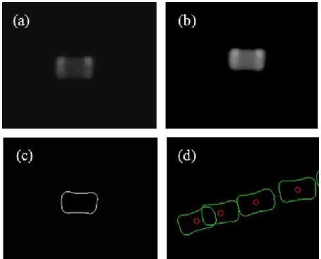
Figure 2.6 Procedure for detecting center of micro – parts: (a) row image, (b) improved image, (c) edge detection by Canny method, and (d) tracked center.
The steps for using the PTV technique in this study are explained in Fig. 2.6. First, a series of images of the motion of a micropart are recorded by the microscope within the focused region of the lens. The raw image shown in Fig. 2.6(a) is extracted from the recorded image series, and its quality is improved as in Fig. 2.6(b) by using image editor software (VW-H1ME, Keygence Co.). Next, the edge of the microparts is detected by Canny method using an approximated threshold defined relatively to the maximum intensity of picture. Fig. 2.6 (c) shows a plot of the edge of the microparts for different value of threshold which is used in this case to obtain the best quality edge. Finally, the center of the microparts is computed by averaging the ensemble of the edge pixels; it is indicated by the circle in Fig. 2.6(d). The steps shown in Fig. 2.6(a) – (d) are executed by using MATLAB libraries.
19
2.3.2 Otsu Thresholding
As mentioned in the section 2.3.1, the position and velocity of a moving micropart were measured by the particle tracking velocimetry (PTV) method. In this method, the edge of the microparts is detected by the Canny filter and the center of the microparts is computed by averaging the ensemble of the edge pixels. However, the orientation and angular velocity of a micropart could not measure by the Canny method. So, the Otsu’s method is applied into the particle tracking velocimetry to determine the orientation and angular velocity of a micropart.
The center of a micropart is detected in two successive images, and the velocity is calculated from the consecutive locations of the center. The steps of the PTV technique in this study are illustrated in Fig. 2.7. The same with the first step of Canny method, a series of images of a moving micropart are recorded by a microscope within the focused region of the microscope. The raw image is extracted from the recorded image series, and then, a global image threshold determined by Otsu’s method (Otsu, N., 1997) is used to convert the intensity image into a binary image, as shown in Fig. 2.7(a). Finally, the center of the micro part is determined as the centroid of the image identified by the circle in Fig. 2.7(b). The orientation of the micropart is obtained by determining the principal axis of the image (William K. Pratt, 2001). The steps shown in Fig. 2.7(a) – (b) are executed using MATLAB libraries.
Figure 2.7 Procedure for detecting position and rotation of microparts: (a) raw image, (b) tracked center.
20 The moment of the image is defined as:
J j K k n k m j
y
F
j
k
x
n
m
M
1 1,
,
(2.1)where F(j,k) is the intensity of the binary image, (J,K) is the size of image, and m-nth is the order moment.
The centroid of the is image is :
(1, 0)
(0, 0)
(0,1)
(0, 0)
c cM
x
M
M
y
M
(2.2)The central moment referred to the center of the image is
1 1
,
,
J K m n c c c j kM
m n
i
x
j
y
F j k
(2.3)The moment of inertia covariance matrix is
)
2
,
0
(
)
1
,
1
(
)
1
,
1
(
)
0
,
2
(
c c c cM
M
M
M
M
(2.4)Let and 2 be eigenvalues of matrix M, and e1 = [e11, e21]T and e2 = [e12, e22]T be the eigenvectors corresponding to and 2 respectivelyOrientation angle of a micropart
is then computed by 21 11 22 12
arctan(
,
)
arctan(
,
)
e
e
e
e
1 2 1 2(
)
(
)
(2.5)2.3.3 Comparison between Canny and Otsu techniques in PTV method
This section presents two techniques of image segmentation, Canny edge detection and Otsu thresholding in the particle tracking velocimetry (PTV) method to investigate the motion of micropart. Depending on the quality of recorded movie of motion
21
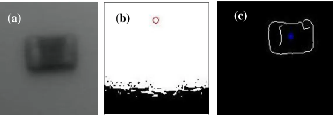
micropart on the saw-tooth surface, which one of techniques was decided. For example: comparison between two techniques for the experiment of a micropart on the zirconia surface and the carbide surface as shown in Fig. 2.8. The tracking center of micropart by Otsu technique in case 1 of Fig. 2.8(b) was unsuccessful because the color zirconia surface is bright close to the color of micropart, so processing separation of light and dark regions was impossible to obtain part of desired region. In this case, Canny technique is more suitable to track edges of micropart as shown with a little noise as in seen Fig. 8(c). In case 2, using PTV method to analyze motion of micropart on the carbide surface. Because the color of carbide material totally contrast to the color of micropart, using both Canny and Otsu techniques give good detection image. In addition, as conclusion above section the orientation and angular velocity of a micropart could not measure by the Canny method. So, the Otsu’s method is applied into the particle tracking velocimetry to determine the orientation and angular velocity of a micropart.
Case 1: Experiment for a micropart on the Zirconia surface
Case 2: Experiment for a micropart on the Carbide surface
Figure 2.8 a) Original image, b) Edge detection by Otsu technique, c) Edge detection by Canny technique
(a)
(b)
(c)
22
2.4 Characteristic of Obtained Surfaces by Technologies
Fabrications
2.4.1 Fabricated surface by dicing saw
A dicing saw (Disco Corporation), a high-precision cutting and grooving machine, can be used for the saw-tooth processing silicon wafers. The saw can be equipped with a variety of diamond blades (Fig 2.10), each for a particular task. The two saw-tooth surface profiles, shown in Fig 2.9 (a) and (b), can be cut in the silicon wafer using bevel-type blades. In these figures, p, l, d, and are the pitch, groove length, and elevation angle of a saw-tooth, respectively. A saw-tooth profile is obtained when p = l; a trapezoidal profile is obtained when p > l.
Mitani at el., (2011) previously used saw-toothed surface of silicon wafer fabricated by a dicing saw. Applying a bevel type blade, authors obtained saw-toothed periodic structure on a silicon wafer (Fig. 2.11). In this case, however, there were fabrication errors at the top teeth because of cracks, and also the shapes of each structure were not perfectly saw-toothed but close to asymmetric sinusoidal wave with low uniformity as shown in Fig. 2.12. They caused variations of contact between fed microparts and feeder surfaces, which affected the feeding stability of microparts.
23
Figure 2.10 A typical diamond blade for saw-tooth process.
Figure 2.11 Saw-toothed silicon wafers fabricated by a dicing saw
Figure 2.12 Microscopic image of a sawtoothed surface fabricated by a dicing saw with a bevel type blade: 3D image synthesized from focusing images by height, and colored contour model
24
2.4.2 Fabricated surface by grinding process
The grinding technology is applied to develop various reflection surfaces for optical communication. This technology can generate periodic V-shape grooved surfaces. Fig. 2.13 shows a grooving blade, which has a beveled in one side and straight in the other. Using this blade, asymmetric fabricated surface can be generated on various materials according to its thickness, 2 mm.
Brass, zirconia, and cemented carbide materials were chosen based on their machinability, with brittleness, low viscosity, and low thermal deformation. These characteristics are suitable to be fabricated into accurate saw-toothed. Figure 2.14 shows the obtained saw-tooth profile on cemented carbide material for example by using the grinding technology, and on other materials will be discussed on the next Chapter.
Figure 2.13 A grooving blade
25
2.4.3 Fabricated surface by femtosecond laser process
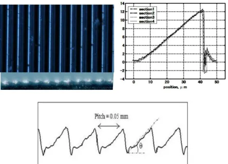
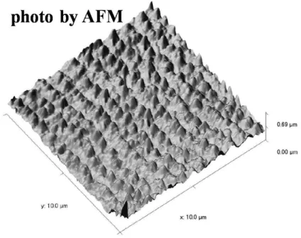
Femtosecond laser technology, which is used to reshape materials, to control chemical reactions, and to fabricate microparts, is also used in microelectromechanical system (MEMS), and to observe super-high-speed phenomena. Materials around the area irradiated in femtosecond laser fabrication are chemically and thermally unaffected. The minute grating structures thus formed on materials such as silicon and stainless steel are of the same order of magnitude as the laser beam pulse wavelength and the periodic structures on the contacting surface reduce friction and adhesion effects by decreasing the contact area. In our study, we applied experimental surfaces which were designed to feed 0402 capaciors 0.4 0.2 0.2 mm in size and 0.1 mg weighting using double-pulsed femtosecond laser irradiation to create an asymmetrical surface (A Mitani and S Hirai, 2009). The feeder surface is stainless steel shim tape 0.5 mm thick, 10 mm wide, and 33 mm long. To make the feeder profile asymmetric, the authors used double-pulsed femtosecond laser beam irradiation in which a single-axis femtosecond laser beam is divided into two, with one side having an angle of 20o and delay of 50 ps. The surface begins moving 50 ps after irradiation by the fist beam, and simultaneous irradiation with the second beam forces the transpirations recoil to shift toward the second beam's incidence angle generation an asymmetrical surface (Fig. 2.15) with many periodic convexities (Fig. 2.16).
26 Figure 2.16 Microfabricated surface periodicity
2.4.4 Fabricated surface by etching process
Etching process, a MEMS (micro electro mechanical system) technology, can generate stable and precise periodic pattern on a single crystal silicon wafer according to an etching mask. The behavior of the etching process, such as etching speed and etching direction, depends upon silicon crystal orientation appeared on the cut side. This means that we can control the surface profile generated on the etched surface by selecting an appropriate orientation of silicon crystal. In the case of a typical crystal orientation surface, for example [100], the etching speed vary according to the etching direction along the crystal surface, then etching process advances isotropically.
We prepared silicon wafers with a plain orientation of [221] in order to generate an asymmetric periodic structure by the etching process. A silicon wafer was thermally oxidized under a temperature of 1000 °C and an oxygen density of 0.2 kg/cm2 with a fluid rate of 5 l/min, then the thermally oxidized film with 300 nm in thickness was generated. After photoresist processing using a spin coater, a periodic slit pattern was exposed on the resist film. The Si02 film was etched by the reactive ion etching (RIE) process of the CHF3 gas with 10 sccm and a radio frequency (RF) power supply energy of 100 W. Removing the resist film, the silicon wafer was etched anisotropically using the ELM-SiM (org), an enchant for high speed anisotropic etching of silicon (Mitsubishi Gas Chemical Company), with a temperature of 80 °C for about 90 min. Then the
27
silicon wafer was fabricated asymmetry. Figure 2.17 shows a microscopic image of an anisotropic etched surface developed in the previous works, captured from the side (Mitani. A and Matsuo.Y, 2011). From this figure, the profile of each tooth was asymmetric triangular shape, and all of them were uniform. We also found that the etching process was stopped at the [111] surface. The elevation angles of both right and left sides were 15.6 ° and 57.4°, respectively, which were close to the theoretical values defined by rotation of silicon crystal, 15.8 ° and 54.7 °, respectively.
However, we found two problems in its sawtooth shape as shown in Figure 2. 18. There was resist film remaining at the top of tooth that influences on the tribology asymmetry because the both side slopes are hidden by them. Also, unexpected over etching was occurred between the right side slope and the resist film. This made it difficult to contact microparts with the right side slope. In order to improve the sawtooth shape, we tried to realign the etching parameters and obtained three different surfaces.
All anisotropic etched surfaces were captured by a scanning electron microscope system (SEM) to obtain geometric parameters of surface profile. The geometric parameters of tooth shape was measured based on tooth model described in Figure 2.19. Figure 2.20 shows the 3D contour models and their surface profiles. Overshoots around the edge at the left side of the flat part and around the bottom of groove can be ignored because they may be caused by scanning error.
Figure 2.17 Microscopic image of a sawtoothed surface fabricated by the anisotropic ething process of [221] oriantation silicon wafer
28
Figure 2.18 Remained resist film on thee anisotropic etched process
29
Figure 2.20 3D analysis model of asymmetric etched surface and their sections of three arbitrary points
2.5 Closing remarks
This chapter has introduced experiment systems, microparts movement tracking method, and the discussion of fabrication techniques dependent surface.
To track the motion of microparts, Particle Tracking Velocity (PTV) was employed. Two techniques of image segmentation, Canny edge detection and Otsu thresholding, were used to determine the position and velocity of a micropart. Canny edge detection was more suitable than Otsu thresholding for grey scale with low noise. In contrast, Otsu thresholding was a good choice to determine the orientation and angular velocity of microparts. In our study, both techniques were used depending on the quality of the images and requirement of the output information.
In this chapter, the dependence of the characteristic of the feeder surface on fabrication technology was also discussed. The discussed fabrication technologies consisted of dicing, grinding, femtosecond laser, and etching processes. By dicing process, saw-tooth patterned profiles on silicon wafer were achieved. However, this process produced the errors at the tooth tops because of cracks. Furthermore, the shapes of the profiles were not perfectly in saw-tooth shapes. The profiles were sometime closed to square wave with low uniformity. Alternatively, grinding technology improved the saw-tooth profiles and this pattern profiles could be achieved on different materials not only on silicon. However, grinding technology could not produce the saw-tooth profiles with submillimeter peak for the experiments on submillimeter microparts.
30
Fortunately, femtosecond laser and etching process could overcome this drawback, since they avoided using an external mechanical contact to the surface. These two techniques allowed us to fabricate a wide range of saw-tooth peaks on a wide range of materials, and then the experiments on various parameters will be enabled.
31
Chapter 3
Principle of Unidirectional Feeding
This chapter presents the principle of feeding system that uses the asymmetrically patterned surface driven by symmetric vibration to transport microparts in one direction. First, the details of micropart such as capacitors used in electrical devices are described. Several dimensions of the microparts are considered and investigated by a microscopy system. Next, the idea using a saw-tooth patterned surface is described to transport microparts unidirectionally with symmetric vibration. The difference between the forces when the microparts contacts to either the edge or the slop of the saw-tooth partterned surface pushes the microparts moving in one direction. Finally, we analyze the contact force as a function of the relative position of a micropart to the saw-tooth.
32
3.1 Introduction
A variety of microparts, such as ceramic chip capacitors and resistors, are currently being produced in large numbers for cellular phones and palm-top PCs. Microparts feeders are applied in factory to make inspecting, feeding, and shipping automatically. To feed along various parts in one direction, different force should be applied according to direction by asymmetric vibration, inclined structure, or sloping mechanism. Contrary, this work proposed to realize unidirectional feeding using an asymmetric surface such as saw-tooth surface. In this case, contact changes according asymmetric frictional property by the asymmetric fabricated surface. Also when feeding along microparts that less than 100 μm in size such as ceramic chip capacitors and resistors, the effect of adhesion between feeder surface and micropart surface is getting larger than inertia since the former is proportional to the area of contact, while the latter is proportional to the volume. In order to analyze the dynamics of microparts moving on such a asymmetric surface as saw-toothed surface, it is essential to consider the effect of both adhesion and inertia. In this chapter, contacts between three types of ceramic chip capacitors and a saw-tooth surface were analyzed based on measurements using a microscopy system.
3.2 Microparts surface inspection equipment
The surface profiles of capacitors and saw-toothed silicon wafers were analyzed using a multi-purpose zoom microscope MULTIZOOM AZ100 (Nikon Instruments Co. Ltd.) With a mono zoom optical system that enables on-axis observation and documentation and built-in optics of from 1 to 8 magnification. In combination with an objective lens of up to 5X magnification, we could take pictures at up to 40 magnification. The microscope also has an automatic focus height positioning device using a stepping motor, then focus height can control at a resolution of 0.54 µm. A digital camera is attached to the top of the microscope, and pictures are forwarded to a computer via USB interface. The resolution of forwarded pictures taken at 40 magnification is 0.276μm/pixel. Each image is forwarded to a personal computer and saved as a bitmap file. We used focus image synthesizing software DynamicEye REAL (Mitani Corp.) to analyze these convexities. The software can synthesize a three
33
dimentional (3D) model from these pictures according to focus height. Sections of the 3D model are yielded to obtain a convexity size and position. By using the DynamicEye Real software, we obtained a 3D model synthesized according to focus height. We could also derive discrete section along any directions of the 3D model. Sections of the 3D model were assessed to obtain a convexity size and position.
3.3 Microparts surface characteristics
Figure 3.1 shows the raw image of ceramic chip capacitors, as examples, which are captured by the microscope. Each capacitor is composed of a conductor with an electrode on either side. The electrodes contact the feeder surface, as they are about 10μm higher than the conductor. There are also many convexities on the surface of the electrode. We obtain a contour line of the synthesized model as shown in Fig. 3.2. In this figure, the convexities on the electrode of the capacitors are defined and analyzed (Mitani et al., 2007). Figure 3.3 shows representative contours along a capacitor, obtained using sensing-pin surface measurement Form Talysurf S5 (Taylor Hobson Corp.).
(a) (b) (c)
Figure 3.1 Microscopy raw image of ceramic chip capacitors: (a) 0402-, (b) 0603-, and (c) 2012- capacitors
34
(a)
35 (c)
Figure 3.2 Measurement results 3D contour line of electrode of ceramic chip capacitors: (a) 0402-, (b) 0603-, and 2012- capacitors
36
(b)
(c)
Figure 3.3 Measured section of capacitors: (a) 0402-, 0603-, and 2012- capacitors
(a) Electro model (b) Convexity
37 Figure 3.5 Saw-tooth surface model
Figure 3.6 Two contacts between a micropart and a saw-tooth
Figure 3.7 Diagram of a micropart feeder with a sawtoothed surface and symmetric vibrations We assume that the convexities in the electrode surface are perfectly spherical, as shown in Fig. 3.4(a) and the feeder surface is saw-toothed (Fig. 3.5). Let r be the radius of the convexity, as shown in Fig. 3.4(b). Recall that is the elevation angle of a
saw-38
tooth, as illustrated in Fig. 3.5. A saw-tooth can contact an electrode in one of the two ways, as shown in Fig. 3.6: a point contact in which the point of a saw-tooth contacts with a convexity, or a slope contact in which the slope side of a saw-tooth contacts with a convexity. Consequently, they drive the microparts in one direction.
In our study, we have researched dynamics motion of microparts on the microparts feeder applied an asymmetric fabricated surface, for example, saw-tooth surface, as a feeder table (Figure 3.7). The asymmetric fabricated surface can feed along microparts in one direction using horizontal and symmetric vibration because contact between a micropart and the asymmetric fabricated surface varies according to the direction of motion. In order to formulate the dynamics of micropart precisely, we need to analyze both inertia caused by vibration of the feeder surface and adhesion according to these contacts.
3.4 Contact between microparts and saw-tooth surface
The driving force which drive the microparts in one direction according to the contact conditions are slope contact and point contact.
3.4.1 Slope contact
Figure 3.8 Statics of each contact condition
Let us assume that a slope pushes a convexity to the left with a contact force F0, as shown in Fig. 3.8(a). The convexity is climbing the slope of the saw-tooth. Let µs be the friction coefficient of the slope contact, frs be the normal force along the slope of the saw-tooth, and fns be the tangent force to the slope of the saw-tooth. Then, the following equations can be derived:
39
(3.1)
(3.2)
Driving force Fs along the x-axis can be expressed as
( ) (3.3)
Note that Fs = - F0 when
3.4.2 Point contact
Let us assume that a point on a saw-tooth contacts a convexity with a contact force F0, as shown in Fig. 3.8(b). Let be the point contact angle and s be the friction
coefficient of the point contact. The driving force is the resultant of the normal force
and the friction force . Driving force Fe along the x-axis can
be expressed as follows:
( ) (3.4)
Note that Fe = 0 when
3.5 Previous feeding experimental results
From based research (Mitani et al., 2007), feeding experiments on the 2012-type capacitors were conducted using a = 300 surface. The voltage on the piezoelectric actuators was a 120-V peak – to – peak square wave. Figs. 3.10, 3.11, and 3.12 show the experimental results for driving frequencies of 10, 15, and 30 Hz, respectively. Fig. 3.10 (a) and (b) shows the trajectories of the microparts over a 1-s period at a driving frequency of 10 Hz. The microparts rotated or jumped in both feeding directions, which shows that feeding is unstable. Fig. 3.11 (a) and (b) shows the trajectories of the microparts over a 4-s period at a driving frequency of 15 Hz. In both the cases, all the microparts moved steadily. The microparts in (b) moved in the direction opposite to those in (a), which proves that the directionality of the feeding is achievable using a saw-tooth surface. Fig. 3.12 (a) and (b) shows the trajectories of the microparts over an 8-s period at a driving frequency of 30 Hz. The feeding distance was short, but the microparts clearly moved in one direction, namely in the direction of the saw-tooth surface. Fig. 3.13(a) and (b) shows the results of the feeding experiments using a θ =
40
60◦ surface. A driving frequency of 15 Hz was applied for 2 s. In the positive direction, the second micropart reached the front of the feeder table in about 2 s. The others did not reach the front of the feeder table while they moved in one direction. In the negative direction, the first micropart moved in the direction opposite to the desired direction. The others stopped in the middle of the feeder surface. Thus, unidirectional feeding was not achieved on the θ = 60◦ surface. No directionality was observed with the θ = 60◦ surface, presumably because the microparts remained still during the slope contact. Some microparts moved faster on the θ = 30◦ surface. The adhesion force on the θ = 60◦ surface was weaker than that on the θ = 30◦ surface.
From the experiments described above, the most stable feeding was achieved when a 15 Hz square wave was used. But it took 4 s or longer the microparts to move 30 mm. For a faster feeding, the driving conditions and surface profile need to be improved. The microparts jumped and revolved when the driving frequency was 10 Hz. Large feeder vibration amplitudes generated high driving forces on the microparts. The edges of the microparts were raised by the collision between the microparts and the saw-teeth. The microparts moved only short distances when the driving frequency was 30 Hz. Amplitudes of the feeder vibration were too low to change the state of contact between the microparts and the saw-teeth from slipping on stopping at point contact.
41
Figure 3.10 Motion of the 2012-type capacitors due to a 10 Hz on a = 300 surface (Mitani et
al., 2007)
Figure 3.11 Motion of the 2012-type capacitors due to a 15 Hz on a = 300 surface (Mitani et
al., 2007)
Figure 3.12 Motion of the 2012-type capacitors due to a 30 Hz on a = 300 surface (Mitani et