Research and Development of Ni/BaCe
0.5Zr
0.3Y
0.2O
3-δHydrogen Electrode with
Fused-Aggregate Network Structure for
Proton-Conducting Solid Oxide Cells
A Doctoral Thesis presented to the Interdisciplinary
Graduate School of Medicine and Engineering University of
Yamanashi
March 2018
Ryosuke Nishikawa
Chapter 1: General introduction
1.1 Background 1
1.2 Hydrogen production method 4
1.3 Solid oxide cells (SOCs) 1.3.1. Solid oxide electrolysis cell (SOEC) 6
1.3.2. Solid oxide fuel cell (SOFC) 9
1.4.Construction of proton-conducting SOCs 1.4.1. Electrolyte material 10
1.4.2. Hydrogen electrode 12
1.4.3. Hydrogen electrode concept 1.4.3.1. Double layer electrode 14
1.4.3.2. Fused-aggregate network structure 15
1.5. My research objective 16
Chapter 2: Synthesis and evaluation of Ni catalyst supported on BaCe0.5Zr 0.3-xY0.2NixO3-δ (BCZYN) with fused-aggregate network structure for hydrogen
electrode of solid oxide cells
2.1. Introduction 27
2.2. Experimental 2.2.1. Sample preparation 29
2.2.2. Single cell fabrication 30
2.2.3. Characterization of sample, CL and CCL 31
2.2.4. Electrochemical measurement 32
2.3. Results and discussion 2.3.1. Characterization of sample 34
2.3.2. Performance of Ni/BCZYN CLs 42
2.4. Conclusions 48
Chapter 3: The cermet electrode performance of Ni-BCZYN with fused-aggregate network structure as hydrogen electrode of solid oxide cells
3.1. Introduction 54
3.2. Experimental 3.2.1. Sample preparation 56
3.2.2. Single cell fabrication 57
3.2.3. Characterization of sample, CL and CCL 58
3.2.4. Electrochemical measurements 59
3.3. Results and discussion 3.3.1. Characterization of samples 60
3.3.2. Double layer hydrogen electrode performance 67
3.4. Conclusions 70
Chapter 4: General conclusion 4.1. Conclusions 76 4.2. Future prospects 78 4.3. References 81 List of publications Meeting abstract Awards Acknowledgements
1
Chapter 1
General Introduction
1.1. Background
The improvement of living standards for human life has led to the increase of the energy demand. The amount of energy consumption originating from fossil fuel in the world has been over 80% each year for the past 25 years (Fig. 1-1) [1].
The fossil fuel itself is limited in amount and causes environmental problems of global warming and atmospheric pollution as an energy source. In Japan, nuclear power and renewable energy are selected as two of the candidate alternative power generation systems to solve these problems (Fig. 1-2) [2]. Until 2010, nuclear power generation comprised about 10% each year. After the Fukushima Daiichi nuclear disaster in 2011,
2
nuclear power generation stopped. After the disaster, nuclear power was replaced by natural gas. It is considered that the utilization of renewable energy sources such as solar power, hydraulic power and wind power should be promoted.
Fig. 1-2 Trend of primary energy supply in Japan. [2]
3
Renewable energy has a priority to be from eco-friendly energy sources, as has been noted around the world. In Japan, the Feed in Tariff system started in 2012 [2], and the generation of renewable energy increased abruptly after 2013 (Fig. 1-3). It was also apparent that the renewable energy was affected frequently by fluctuations of weather and climate, and that the leveling of the renewable energy was quite important. Hydrogen, organic hydrides and ammonia have attracted attention as energy carriers for the leveling of renewable energy. Among these, hydrogen has high energy density based on weight [4]. If the hydrogen is generated from by use of excess power during the daytime hours, and stored/carried by tank, hydrogen will be one of the more important energy carriers.
4
1.2. Hydrogen production methods
Hydrogen can be produced by purification of by-product gas, steam reforming of natural
gas or biological resources [5, 6], photochemical processes [7], and water and steam
electrolysis [8-13]. Low cost hydrogen generation by purification of by-product or steam
reforming of natural gas not only requires this fossil fuel but also produces large amounts
of CO2 [5]. Steam reforming of biological products such as biomass is high in cost and
low in energy efficiency. Hydrogen produced by photochemical processes with ultraviolet
radiation has a problem of low quantum yield with high cost. Compared to previous
methods, water and steam electrolysis has the ability to produce highly purified hydrogen
directly and also has the possibility to be a zero-CO2 emission process by the use of
renewable energy.
Water and steam electrolysis cells are generally classified into three types according to
the electrolyte, such as alkaline electrolysis cells (AECs), polymer electrolyte membrane
water electrolyzers (PEMWEs), and solid oxide cells such as steam electrolysis (SOECs).
AECs, which are composed of a Ni electrode and 25~30% KOH electrolyte have already
been commercialized. PEMWEs are constructed with a proton exchange membrane
sandwiched by two noble metal catalyst electrodes. SOECs include a yttria-stabilized
5
oxygen electrode and a Ni-YSZ hydrogen electrode. They have a high conversion
efficiency due to their high temperature operation. SOECs can generate hydrogen and
also can contribute to the leveling of electric power generation via reversible operation in
fuel cells. In particular, SOECs have the advantage of operating with high efficiency.
Moreover, there are two types based on the electrolyte. One is oxide ion-conducting, and
the other is proton-conducting. Hydrogen produced by oxide ion-conducting SOECs includes a slight amount of unreacted water. Hydrogen produced by proton-conducting
SOECs is high in purity, without unreacted water, and this is preferable to supply to the
fuel cell vehicle (FCV) [14]. It is expected that the utilization of FCVs will contribute to decreasing CO2 emissions and can contribute to the alleviation of environmental problems.
Hydrogen production by proton-conducting SOECs is an important technology to help
6
1.3. Solid oxide cells (SOCs)
1.3.1. Solid oxide electrolysis cell (SOEC)
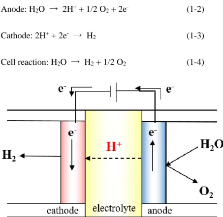
A schematic illustration of a proton-conducting SOEC is shown as Fig. 1-4. Water vapor
is supplied to the anode, and protons, electrons and oxygen molecules are emitted at the
anode. The generated protons move through the solid oxide electrolyte toward the cathode.
Protons and electrons react to produce hydrogen. These electrode reactions proceed as
follows:
Anode: H2O → 2H+ + 1/2 O2 + 2e- (1-2)
Cathode: 2H+ + 2e- → H2 (1-3)
Cell reaction: H2O → H2 + 1/2 O2 (1-4)
7
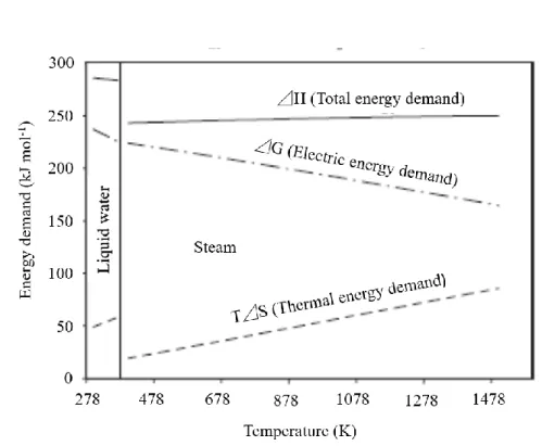
The advantages of high temperature operation are a high electrode reaction rate and a lack
of a requirement of a noble metal catalyst. The theoretical electrolysis efficiency (ε) of a
SOEC is expressed by the following equation.
ε = (Ho / 2F) / Eo (1-5)
Where Ho is the standard enthalpy change, F is the Faraday constant and Eo is the
standard electrolysis voltage. Eo in the above equation is expressed by the Nernst equation
as follows.
Eo = Go / 2F (1-6)
Where Go is the standard Gibbs free energy change of the cell reaction. The Go and Eo
decrease with increasing operating temperature (Fig. 1-5), and the theoretical conversion
efficiency becomes high.
The first results for a proton-conducting SOEC were reported by Iwahara et al. [15].
Obvious hydrogen evolution was observed, and the current efficiency reached 50-95% in
the 0.1-0.8A cm-2 current range with 1 atm of water vapor. Since this report, both electrolytes and electrode materials for proton-conducting cells have been intensively studied, continuing to the present [16-18].
8
9
1.3.2. Solid oxide fuel cell (SOFC)
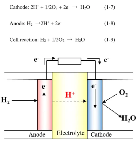
A schematic illustration of a proton-conducting SOFC is shown as Fig. 1-6. The electric
power generation by SOFCs has a high conversion efficiency due to the use of waste heat.
Air (oxygen) and hydrogen are supplied to the cathode and the anodes, respectively. When
two electrodes are connected via an external circuit, protons and electrons are emitted at
the anode. The generated protons move through the electrolyte towards the cathode and
react with oxygen and electrons to produce water vapor. The reactions at each electrode
of the SOFC proceed as follows:
Cathode: 2H+ + 1/2O2 + 2e- → H2O (1-7)
Anode: H2 →2H+ + 2e- (1-8)
Cell reaction: H2 + 1/2O2 → H2O (1-9)
10
The fuel cell reaction is the reverse of the steam electrolysis reaction, and the absolute
values of Ho, Go, and Eo are the same as those shown in Fig. 1-5. The theoretical
power generation efficiency of the SOFC is given shown by the following equation. Go / Ho = -2FEo / Ho (1-10)
The absolute value of G decreases with increasing operating temperature. Eo decreases,
and the theoretical power generation efficiency also decreases at high operating
temperatures. The theoretical efficiency of the SOFC decreases with increasing operating
temperature.
1.4. Construction of proton-conducting SOCs
1.4.1. Electrolyte material
The electrolyte material must be a proton conductor and highly densified sintered body
to maintain the separation of the reactant gases. These requirements of electrolyte material
are shown below:
High proton conductivity and proton transport number
thermodynamically stable in the presence of oxygen, hydrogen and water vapor highly densified sintered body
11
To fulfill these requirements, perovskite type oxides, ABO3 (A site cation is Ba or Sr, B
site cation is Ce or Zr), have been the most studied as proton-conducting materials [15-28].
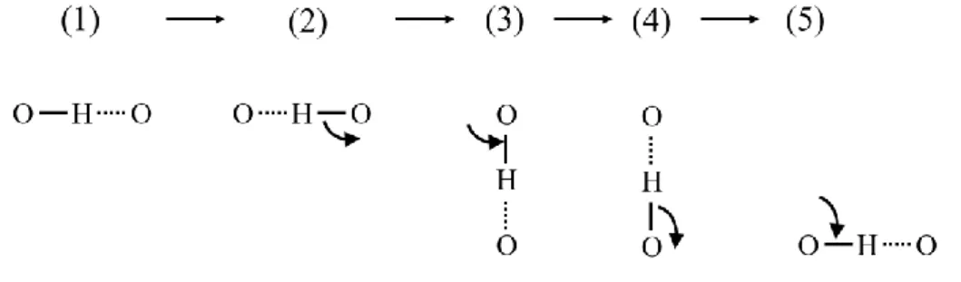
An illustration of a proton-conductive mechanism is shown in Figure 1-7. Sata et al. reported that there are two stable positions between two adjacent oxygen atoms in a perovskite crystal lattice, one of which can be occupied by protons. This proton rotates around the oxygen, while maintaining the O-H bond, and in some cases disconnects its bond and forms another O-H bond with an adjacent oxygen [29].
Among the various proton-conducting materials, BaCeO3 and SrCeO3 perovskites exhibit
high conductivity but are thermodynamically unstable under CO2 and water vapor
[19-24]. SrZrO3 and BaZrO3 perovskites exhibit low proton conductivity but are
thermodynamically stable [25-28]. Recent studies of BaCeO3-BaZrO3 solid solutions
have reported good results for both thermodynamic stability and proton conductivity [28-32]. Even though BaCeO3-BaZrO3 solid solutions are thermodynamically stable and
12
exhibit high conductivity, the conductivity of this solid solution is lower than that of the BaCeO3 system. To solve this problem, the production of dense, highly conductive
electrolyte thin films have been successful in hydrogen electrode-supported cells [34-36].
1.4.2. Hydrogen electrode
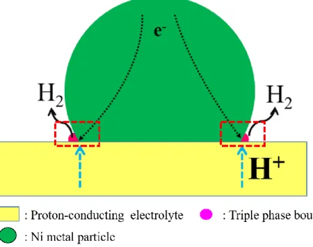
Most studies of hydrogen electrodes for proton-conducting SOCs have used Ni-based
proton-conducting material composites. A schematic illustration of a hydrogen
electrode-supported cell is shown as Fig. 1-8.
Recently, the hydrogen electrode has comprised a functional layer (FL) and a support
layer (SL). The FL, which is made up of fine powders, plays a role as a conductive
pathway for protons and electrons near the electrolyte thin film. The porous SL acts as a
gas diffusion pathway for produced hydrogen. The reaction site for the hydrogen
evolution reaction (HER) is shown as Fig. 1-9. Protons are supplied from the oxygen
electrode to the hydrogen electrode through the electrolyte, and hydrogen is emitted by Fig. 1-8 Schematic illustration of hydrogen electrode supported cell.
13
the reaction of protons and electrons at the reaction site, the so-called triple-phase
boundary (TPB), where electrons, protons and gas phase meet.
This reaction site is limited due to point contact between the proton-conducting material
and the electron-conducting material, such as Ni. The research on microstructures of the
hydrogen electrode is still lacking to improve the electrode performance. From the
viewpoint of reaction sites, it is important to clarify the optimal microstructure of the
hydrogen electrode for the proton-conducting cell.
14
1.4.3. Hydrogen electrode concept
1.4.3.1. Double layer electrode
To improve the electrode performance, Watanabe and coworkers proposed the highly
dispersed nanometer-sized Ni on mixed oxide ionically/electronically conductive
(MOEC) oxides with large effective reaction zone (ERZ) in the oxide-ion conducting
cell [37-41]. The design concepts of the electrode are 1) application of materials with a
highly conductive MOEC oxide as a porous electrode, 2) enlargement of the ERZ by
controlling the microstructure of the porous electrode using MOEC oxides, where oxide
ions, electrons, and reactant gases can have maximum contact, and 3) activation of the
reaction by highly dispersed electrocatalysts on the surface of the porous electrode using
MOEC oxides. Moreover, Uchida and coworkers also proposed the concept of the
double-layer (DL) electrode comprising a catalyst layer (CL) / current-collecting layer
(CCL) for the oxide ion-conducting SOEC to enhance the performance of the hydrogen
electrode. The performance of the DL electrode for oxide ion-conducting SOECs
improved with the high dispersion of Ni-based catalysts, the amount of the Ni catalysts
in the CL, the volume fraction of micrometer-sized Ni in the CCL, and the porosity and
thickness of each layer [42, 43]. The requirement of the microstructure with highly
15
1.4.3.2. Fused-aggregate network structure
The ERZ is constructed on the interfaces between Ni particles and ionic conductor and
is also constructed on the surface of the mixed ionic-electronic conductor. The surface
area of the mixed conductor increases with decreasing particle size of the mixed conductor.
There is danger that the contact resistance between these mixed conductor particles will
increase with decreasing particle size. In order to decrease the particle size and restrict
the contact resistance, it is necessary to provide the support material with a unique
microstructure. Carbon black (CB) has used as a electrode support material for polymer
electrolyte fuel cells (PEFCs), whose microstructure has particles partially fused with
nearest neighbors, constructing a chain-like structure (fused-aggregate network structure,
(fans)), gas diffusion pathway, electron transport pathway and high surface area [44, 45].
Recently, rutile-structured oxide nanoparticles with fused-aggregate network structure
were developed, whose microstructure is also similar to that of carbon black [46-52]. The
developed materials exhibited comparable catalytic activity and superior durability
compared to a conventional Pt/CB catalyst. The microstructure with fused-aggregate
network structure has a possibility to be used as the support material for the hydrogen
16
1.5. My research objective
From the above viewpoints, I have sought to apply the DL electrode (CL:
nanometer-sized Ni dispersed on porous mixed protonically/electronically conductive (MPEC)
oxide; CCL: composite of Ni MPEC oxide) to the hydrogen electrode of
proton-conducting SOCs, based on the electrode design concept. A CCL of micrometer-sized
Ni-MPEC oxide cermet is formed on the top of the CL to supply a highly electronically
conductive layer, with high gas diffusion rate from the separator (interconnect) to the CL,
and intimate contact between the separator and the CL. The slight amount of Ni doping
in the proton-conducting oxide enhanced the electronic conductivity in the oxide, which
was one of the most promising MPEC oxides for application. In addition, I expected that
nanoparticles with the fused-aggregate network structure (fans) would also be well suited
for these design concepts for the CLs of the hydrogen electrode in a proton-conducting
SOC. The details of the electrode concept will be explained in the next chapter.
In this chapter, I briefly explain the outline of the thesis and briefly explain the content of the chapters that follow.
In chapter 2, I tried to synthesize BaCe0.5Zr0.3-xY0.2NixO3-δ (BCZYN, x = 0, 0.03) with
fused-aggregate network structure. First, I prepared the DL hydrogen electrode and evaluated the electrode performance. I also investigated the relationship between
17
electrode performance and Ni loading amount.
In chapter 3, I applied Ni metal with fused-aggregate network structure (Ni(fans)) in the CL of the DL hydrogen electrode in order to introduce electronically conductive pathways into the CL, and I investigated the electrode performance compared to that without the Ni(fans) electrode.
Finally, in chapter 4, I summarize the results of all chapters and explain the guidelines for high performance hydrogen electrodes for proton-conducting SOCs.
18
References
[1] BP statistical Review of World Energy June 2017, published by BP global (2017):
https://www.bp.com/content/dam/bp/en/corporate/pdf/energy-economics/statistical-review-2017/bp-statistical-review-of-world-energy-2017-full-report.pdf. [2]Japan’s Energy White Paper 2017 part2 Energy trends:
http://www.enecho.meti.go.jp/about/whitepaper/2017pdf/whitepaper2017pdf_2_1.pdf. [3] Japan’s Energy White Paper 2017 (brochure):
http://www.enecho.meti.go.jp/en/category/whitepaper/pdf/whitepaper_2017.pdf.
[4] J. Graetz,New approaches to hydrogen storage, Chem. Soc. Rev., 38 (2009), 73-82.
[5] T. Rostrup-Nielsen, Manufacture of hydrogen, Catal. Today, 106 (2005), 293-296.
[6] S. Shobana, G. D. Saratale, A. Pugazhendhi, S. Arvindnarayan, S. Periyasamy, G.
Kumar and S.-H. Kim, Fermentative hydrogen production from mixed and pure
microalgae biomass: Key challenges and possible opportunities, Int. Hydrogen. Energy,
42 (2017), 26440-26453.
[7] P. Sharma and M. L. Kolhe, Review of sustainable solar hydrogen production using
photon fuel on artificial leaf, Int. J. Hydrogen. Energy, 42 (2017), 22704-22712.
[8] F. Barbir, PEM electrolysis for production of hydrogen from renewable energy
19
[9] P. Millet, R. Ngameni, S.A. Grigoriev, N. Mbemba, F. Brisset, A. Ranjbari and
C. Etie´vant, PEM water electrolyzers: From electrocatalysis to stack development, Int.
J. Hydrogen Energy, 35 (2010), 5043-5052.
[10] P. Millet, N. Mbemba, S.A. Grigoriev, V.N. Fateev, A. Aukauloo and C. Etie´vant,
Platinum and palladium nano-particles supported by graphitic nano-fibers as catalysts
for PEM water electrolysis, Int. J. Hydrogen Energy, 36 (2011), 4134-4142.
[11] T. Pu, W. Tan, H. Shi, Y. Na, J. Lu and B. Zhu, Steam/CO2 electrolysis in
symmetric solid oxide electrolysis cell with barium cerate-carbonate composite
electrolyte, Electrochim. Acta, 190 (2016), 193-198.
[12] Z. Sun, E. Fabbri, L. Bi and E. Traversa, Lowering grain boundary resistance of
BaZr0.8Y0.2O3−δ with LiNO3 sintering-aid improves proton conductivity for fuel cell
operation, Phys. Chem. Chem. Phys., 13 (2011), 7692-7700.
[13] H. Uchida, P. Puengjinda, K. Miyano, K. Shimura, H. Nishino, K. Kakinuma, M. E.
Brito and M. Watanabe, Effect of Microstructure on Performances of Hydrogen and
Oxygen Electrodes for Reversible SOEC/SOFC, ECS Trans., 68 (2015), 3307-3313.
[14] International standardization for hydrogen quality for fuel cell vehicle,
20
[15] H. Iwahara, T. Esaka, H. Uchida and N. Maeda, Proton conduction in sintered
oxides and its application to steam electrolysis for hydrogen production, Solid state
ionics, 3-4 (1981), 359-363.
[16] K. Xie, Y. Q. Zhang, G. Y. Meng and J. T. S. Irvine, Electrochemical reduction of
CO2 in a proton conducting solid oxide electrolyser, J. Mater. Chem., 21 (2011), 195-198.
[17] T. Pu, W. Tan, H. Shi, Y. Na, J. Lu and B. Zhu, Steam/CO2 electrolysis in symmetric
solid oxide electrolysis cell with barium cerate-carbonate composite electrolyte,
Electrochim. Acta, 190 (2016), 193-198.
[18] T. Kobayashi, S. Morishita, K. Abe and H. Iwahara, Reduction of nitrogen oxide by
a steam electrolysis cell using a proton conducting electrolyte, Solid State Ionics, 86-88
(1996), 603-607.
[19] H. Iwahara, H. Uchida, K. Ono and K. Ogaki, Proton Conduction in Sintered Oxides Based on BaCeO3, J. Electrochem. Soc., 135 (1988), 529-533.
[20] Y. Okuyama, K. Isa, Y. S. Lee, T. Sakai and H. Matsumoto, Incorporation and
conduction of proton in SrCe0.9−xZrxY0.1O3–δ, Solid State Ionics, 275 (2015), 35-38.
[21] K. Katahira, Y. Kohchi, T. Shimura and H. Iwahara, Protonic conduction in
21
[22] S. Gopalan and A. V. Virkar, Thermodynamic Stabilities of SrCeO3 and BaCeO3
Using a Molten Salt Method and Galvanic Cells, J. Electrochem. Soc., 140 (1993), 1060-1065.
[23] H. Iwahara, H. Uchida, K. Ogaki and H. Nagoto, Nernstian Hydrogen Sensor Using BaCeO3 ‐ Based , Proton‐Conducting Ceramics Operative at 200°–900°C, J. Electrochem.
Soc., 138 (1991) 295-299.
[24] S. Hamakawa, T. Hibino and H. Iwahara, Electrochemical Hydrogen Permeation in a Proton‐Hole Mixed Conductor and Its Application to a Membrane Reactor, J. Electrochem. Soc., 141 (1994), 1720-1725.
[25] H. Iwahara, Proton conducting ceramics and their applications, Solid State Ionics,
86-88 (1996), 9-15.
[26] T. Kobayashi, K. Abe, Y. Ukyo and H. Matsumoto, Study on current efficiency of
steam electrolysis using a partial protonic conductor SrZr0.9Yb0.1O3−α, Solid State Ionics,
138 (2001), 243-251.
[27] J. Mullera, K. D. Kreuer, J. Mejer, S. Matsuo and M. Ishigame, A conductivity and
thermal gravimetric analysis of a Y-doped SrZrO3 single crystal, Solid State Ionics, 97
22
[28] P. Babilo, T. Uda and S. M. Haile, Processing of yttrium-doped barium zirconate for
high proton conductivity, J. Mater. Res., 22 (2007), 1322-1330.
[29] I. Ahmed, S. G. Eriksson, E. Ahlberg, C. S. Knee, H. Götlind, L. G. Johansson, M.
Karlsson, A. Matic and L. Börjesson, Structural study and proton conductivity in
Yb-doped BaZrO3, Solid State Ionics, 178 (2007), 515-520.
[30] N. Sata, H. Matsuta, Y. Akiyama, Y. Chiba, M. Ishigame and S. Shin, Fabrication
of proton conducting thin films of SrZrO3 and SrCeO3 and their fundamental
characterization, Solid state Ionics, 97 (1997), 437-441.
[31] E. Fabbri, A. D’Epifanio, E. D. Bartolomeo, S. Licoccia and E. Traversa, Tailoring the chemical stability of Ba(Ce0.8−xZrx)Y0.2O3−δ protonic conductors for Intermediate
Temperature Solid Oxide Fuel Cells (IT-SOFCs), Solid State Ionics, 179 (2008), 558-564.
[32] J. Bu, P. G. Jönsson and Z. Zhao, Sintering behaviour of the protonic conductors
BaZrxCe0.8-xLn0.2O3-δ (x=0.8, 0.5, 0.1; Ln=Y, Sm, Gd, Dy) during the solid-state
reactive-sintering process, Ceram. Int., 41 (2015), 2558-2564.
[33] Y. Guo, Y. Lin, R. Ran and Z. Shao, Zirconium doping effect on the performance of
proton-conducting BaZryCe0.8−yY0.2O3−δ (0.0 ≤ y ≤ 0.8) for fuel cell applications, J. Power
23
[34] P. Sawant, S. Varma, B. N. Wani and S. R. Bharadwaj, Synthesis, stability and
conductivity of BaCe0.8−xZrxY0.2O3−δ as electrolyte for proton conducting SOFC, Int. J.
Hydrogen Energy, 37 (2012), 3848-3856.
[35] J. Lagaeva, D. Medvedev, A. Demin and P. Tsiakaras, Insights on thermal and
transport features of BaCe0.8−xZrxY0.2O3−δ proton-conducting materials, J. Power Sources,
278 (2015), 436-444.
[36] F. He, D. Song, R. Peng, G. Meng and S. Yang, Electrode performance and analysis
of reversible solid oxide fuel cells with proton conducting electrolyte of
BaCe0.5Zr0.3Y0.2O3−δ, J. Power Sources, 195 (2010), 3359-3364.
[37] Y. Lao, S. Zhong, F. He, Z. Wang, R. Peng and Y. Lu, Cobalt-doped BaZrO3: A single
phase air electrode material for reversible solid oxide cells, Int. J. Hydrogen Energy, 37
(2012), 12522-12527.
[38] Y. Yoo and N. Lim, Performance and stability of proton conducting solid oxide fuel
cells based on yttrium-doped barium cerate-zirconate thin-film electrolyte, J. Power
Sources, 229 (2013), 48-57.
[39] M. Watanabe, H. Uchida and M. Yoshida, Effect of ionic conductivity of zirconia electrolytes on the polarization behavior of ceria‐based anodes in solid oxide fuel cells, J. Electrochem. Soc., 144 (1997), 1739-1743.
24
[40] M. Watanabe, H. Uchida, M. Shibata, N. Mochizuki and K. Amikura, High
performance catalyzed‐reaction layer for medium temperature operating solid oxide fuel
cells, J. Electrochem. Soc., 141 (1994)342-346.
[41] H. Uchida, N. Mochizuki and M. Watanabe, High‐performance electrode for medium‐temperature operating solid oxide fuel cells polarization property of ceria‐based anode with highly dispersed ruthenium catalysts in (H2+CO2+H2O) gas, J. Electrochem.
Soc., 143 (1996), 1700-1704.
[42] S. Suzuki, H. Uchida and M. Watanabe, Interaction of samaria-doped ceria anode
with highly dispersed Ni catalysts in a medium-temperature solid oxide fuel cell during
long-term operation, Solid State Ionics, 177 (2006), 359-365.
[43] H. Uchida, T. Osuga and M. Watanabe, High‐performance electrode for medium‐
temperature solid oxide fuel cell control of microstructure of ceria‐based anodes with
highly dispersed ruthenium electrocatalysts, J. Electrochem. Soc., 146 (1999),
1677-1682.
[44] H. Uchida, P. Puengjinda, K. Miyano, K. Shimura, H. Nishino, K. Kakinuma M. E.
Brito and M. Watanabe, Effect of Microstructure on Performances of Hydrogen and
25
[45] A. Ohma, K. Shinohara, A. Iiyama, T. Yoshida and A. Daimaru, Membrane and Catalyst Performance Targets for Automotive Fuel Cells by FCCJ Membrane, Catalyst, MEA WG, ECS Trans., 41(1) (2011), 775-784.
[46] T. Yoda, H. Uchida and M. Watanabe, Effects of operating potential and temperature
on degradation of electrocatalyst layer for PEFCs, Electrochim. Acta, 52 (2007),
5997-6005.
[47] K. Kakinuma, M. Uchida, T. Kamino, H. Uchida and M. Watanabe, Synthesis and
electrochemical characterization of Pt catalyst supported on Sn0.96Sb0.04O2−δ with a
network structure, Electrochim. Acta, 56 (2011), 2881-2887.
[48] Y. Senoo, K. Taniguchi, K. Kakinuma, M. Uchida, H. Uchida, S. Deki and M.
Watanabe, Cathodic performance and high potential durability of Ta-SnO2−δ-supported Pt
catalysts for PEFC cathodes, Electrochem. Commun., 51 (2015), 37-40.
[49] Y. Senoo, K. Kakinuma, M. Uchida, H. Uchida, S. Deki and M. Watanabe,
Improvements in electrical and electrochemical properties of Nb-doped SnO2−δ supports
26
[50] K. Kakinuma, Y. Chino, Y. Senoo, M. Uchida, T. Kamino, H. Uchida, S. Deki and
M. Watanabe, Characterization of Pt catalysts on Nb-doped and Sb-doped SnO2−δ support
materials with aggregated structure by rotating disk electrode and fuel cell measurements,
Electrochim. Acta, 110 (2013), 316-324.
[51] K. Kakinuma, I.-T. Kim, Y. Senoo, H. Yano, M. Watanabe and M. Uchida,
Electrochemical oxidation of hydrolyzed poly oxymethylene-dimethyl ether by PtRu
Catalysts on Nb-Doped SnO2−δ Supports for direct oxidation fuel cells, ACS Appl. Mater.
Interfaces, 6 (2014), 22138-22145.
[52] Y. Chino, K. Taniguchi, Y. Senoo, K. Kakinuma, M. Hara, M. Watanabe and M.
Uchida, Effect of added graphitized CB on both performance and durability of
Pt/Nb-SnO2 cathodes for PEFCs, J. Electrochem. Soc., 162 (2015), F736-F743.
[53] Y. Chino, K. Kakinuma, D.A. Tryk, M. Watanabe and M. Uchida, Influence of Pt
loading and cell potential on the HF ohmic resistance of an Nb-Doped SnO2-supported Pt
27
Chapter 2
Synthesis and evaluation of Ni catalyst supported on BaCe0.5Zr0.3-xY0.2NixO3-δ
(BCZYN) with fused-aggregate network structure for hydrogen electrode of solid oxide cells
2.1. Introduction
Composites of Ni and proton-conducting material are used as hydrogen electrodes for
proton-conducting SOCs [1-3]. The reaction zone of the composite electrode is limited
by the point contact between Ni and proton-conducting material [4-8]. The development
of a new design concept for hydrogen electrode with wide reaction zone is necessary to
improve the electrode performance, and I proposed the double layer (DL) electrode as the
hydrogen electrode for proton-conducting cells, as shown in Fig. 3-1. This hydrogen
electrode, which was constructed by this DL electrode concept, has shown high electrode
performance as the hydrogen electrode of oxide ionically conductive SOECs [9, 10].
Moreover, support materials with fused-aggregate network structure have the capability
to construct electron and proton conduction pathways, gas diffusion pathways and high
surface area, due to the small nanoparticle size. These capabilities are effective for the
28
applied the DL electrode concept and the mixed protonically/electronically conductive
(MPEC) oxide with fused-aggregate network structure to improve the electrode
performance.
In this chapter, I synthesized the perovskite-type structured MPEC oxide of
BaCe0.5Zr0.3Y0.2O3-δ and BaCe0.5Zr0.27Y0.2Ni0.03O3-δ with fused-aggregate network
structure (BCZY(fans) and BCZYN(fans)) by the flame-oxide synthesis method, and I
prepared the DL hydrogen electrode. I investigated the microstructure and electrode
performance of the DL hydrogen electrode with the relationship of the reaction zone.
Fig. 2-1 Schematic images of double layer (DL) electrode for hydrogen electrode of proton conducting solid oxide electrolysis cells (SOECs).
29
2.2. Experimental
2.2.1. Sample preparation
BCZYN (x = 0 and 0.03) nanoparticle powders with a fused-aggregate network structure
were prepared by the flame oxide synthesis method [11-17]. Briefly, reagent grade Ba,
Ce, Zr, Y, and Ni 2-ethylhexanoates (Nihon Kagaku Sangyo Co. Ltd., Tokyo, Japan) were
mixed in desired ratios with terpene oil as starting materials. The BCZYN (x = 0 and
0.03) powders were obtained by spraying the starting materials into the flame of a mixture
of propane and oxygen. The BCZY(CCL) and BCZY(EL) were prepared by the
solid-state reaction method. Starting materials of BaCO3 (purity 99.9%, Kanto Chemical Co.
Inc., Tokyo, Japan), CeO2 (purity 99.9%, Rare Metallic Co., Tokyo, Japan), ZrO2 (purity
99.9%, Tosoh Co., Ltd., Tokyo, Japan), Y2O3 (purity 99.9%, Kanto Chemical Co. Inc.,
Tokyo, Japan) were mixed in desired ratios with ethanol by ball milling (300 rpm, P-6,
Fritsch Co., Ltd., Idar-Oberstein, Germany) for 3 h, were calcined at 1500 °C in air for
10 h, and were separated by sieving (#400 mesh). Then, the sieved powders were pressed
under isostatic pressure (200 MPa) into a columnar shape (diameter 13 mm, thickness 1.0
mm), and sintered again at 1650 °C for 10 h with the use of BCZY(CCL) and BCZY(EL)
powder beds to prevent the barium evaporation from the respective pressed samples [7].
30
The obtained BCZY(CCL) sintered disk was crushed and reground with isopropanol by
ball milling (300 rpm) for 3 h to a sub-micrometer-sized powder (≤0.3 µm) in order to
prepare the Ni-BCZY(CCL) CCL.
2.2.2. Single cell fabrication
Porous scaffolds of BCZYN (x = 0 and 0.03) powders were synthesized onto the
BCZY(EL) sintered disk. In order to maintain the porosity of the BCZYN (x = 0 and 0.03)
scaffold, carbon black (SB220, Asahi Carbon, Co., Ltd., Niigata, Japan) was added as a
pore-former to the CL pastes, which were screen-printed on the BCZY(EL) sintered disk
and heat-treated at 1000 °C for 4 h in N2. Commercial NiO powder (Kanto Chemical Co.,
Inc., Tokyo, Japan), BCZY(CCL) powder and carbon black pore former were mixed with
60 vol % water by ball-milling to produce the CCL pastes. The latter were screen-printed
on the CL scaffold by tape-casting and were co-sintered at 1050 °C for 4 h in N2. A paste
of Pt-BCZY (Pt:BCZY(CCL) = 80:20 (vol %)) with the additive polymethyl methacrylate
(PMMA) as a pore former was also screen-printed on the opposite side of the BCZY(EL)
to form a Pt-BCZY composite counter electrode.
Ni nanoparticle catalysts were loaded on the BCZYN (x = 0 and 0.03) scaffold by use
31
the BCZYN (x = 0 and 0.03) scaffold through the CCL, followed by heat-treatment at
400 °C for 30 min to form NiO nanoparticles. The Ni loading amounts in the CLs were
adjusted at values from 10 vol % to 30 vol %. The CLs obtained were reduced in dry
hydrogen at the cell temperature (Tcell) = 700 °C for 1 h prior to the performance
evaluation as Ni/BCZYN.
2.2.3. Characterization of sample, CL and CCL
The crystalline phases of the samples were characterized by XRD (RINT-TTR 3, Rigaku
Co., Tokyo, Japan). The chemical compositions of Ni, BCZYN (x = 0 and 0.03),
BCZY(C), BCZY(EL) were evaluated by inductively coupled plasma-mass spectroscopy
(ICP-MS, 7700CX, Agilent Technologies, Inc., CA, USA). The electrical conductivity
for BCZYN (x = 0 and 0.03) was measured as a function of temperature in 4% hydrogen
atmosphere (Ar balance) by the direct current (DC) four-probe method. Each sample for
electrical conductivity measurement was sintered to densify it at 1650 °C in a powder bed.
The microstructure of the CL and Ni particle size were characterized by STEM (HD2700,
Hitachi High-Technologies Co., Tokyo, Japan) equipped with EDX (Xflash®, Bruker
32
prepared with a focused ion beam system (FIB, FB2200, Hitachi High-Technologies Co.,
Tokyo, Japan).
2.2.4. Electrochemical measurement
The set-up for the test cell was described in Fig. 3-2. The test cell was sealed with a gold
ring. The area-specific ohmic resistance and steady-state IR-free polarization
characteristics of the hydrogen electrodes were evaluated at Tcell = 700 °C by the current
interruption method in a three-electrode configuration with humidified hydrogen (H2 flow
rate = 30 cm3 min−1), while supplying dry 4% hydrogen (balance nitrogen) at 30 cm3
min−1 to the counter electrode. A off pulse of 100 ms was applied from a
current-pulse generator (NPGS101-2A, Nikko Keisoku Ltd., Atsugi, Japan), and the resulting
potential responses were recorded with a storage oscilloscope (VC-6045, Hitachi Co.,
Tokyo, Japan). The proton transference number was evaluated by use of an electromotive
force measurement from 600 °C to 800 °C with a test cell supplied with pure
hydrogen/4% hydrogen (balance nitrogen). The electromotive force of the cell measured
by use of the BCZY(EL) agreed well with theoretical values from 600 °C to 700 °C. The
proton transference number of BCZY(EL) was confirmed to be unity in the measurement
33
All of the IR-free current-potential polarization curves were obtained at steady-state,
after the test cells were conditioned by repeated galvanostatic load cycles at Tcell = 700 °C.
The current density (j) was increased from 0 to −0.035 A cm−2 as the hydrogen generation
condition. Then, j was decreased from −0.035 A cm−2 to zero. The next inverse trapezoid
current-time protocol was carried out between 0 and 0.035 A cm−2. I also checked the
ohmic resistance of the test cell in the whole current density range in order to confirm
that the IR loss of the test cell displayed a completely linear relationship of current density
at Tcell = 700 °C.
34
2.3. Results and discussion
2.3.1. Characterization of samples
The X-ray powder diffraction (XRD) profiles of the BCZYN (x = 0 and 0.03) with
fused-aggregate network structure, CCLs of submicrometer-sized BaCe0.5Zr0.3Y0.2O3−δ
(BCZY(CCL)) and electrolyte BaCe0.1Zr0.7Y0.2O3−δ (BCZY(EL)) are shown in Figure
3-3 (a),(b). All of the phases were determined to be the pseudo-cubic perovskite structure,
with no impurity phases. The crystallite sizes of BCZYN (x = 0 and 0.03), BCZY(CCL)
and BCZY(EL), which were determined by applying the Scherrer equation to the XRD
peak of the (110) plane, were 28.9 nm (BCZYN (x = 0)), 22.7 nm (BCZYN (x = 0.03)),
38.3 nm (BCZY(CCL)), and 29.7 nm (BCZY(EL)). The transmission electron
microscopy (TEM) images of BCZYN (x = 0 and 0.03) nanoparticles are shown in the
inset of Figure 3-4 (a). The nanoparticles were partially fused with nearest neighbors and
constructed chain-like microstructures, the fused-aggregate network structure referred to
earlier [11–17]. The XRD profiles of Ni/BCZYN (x = 0 and 0.03) CLs sintered at 1000 °C
in 4% hydrogen atmosphere (N2 balance) are also displayed in Figure 3-4 (a). All of the
peaks were determined to be assigned to the pseudo-cubic BCZYN (x = 0 and 0.03)
phases and Ni metal (2θ = 44.50°, 51.85°, 76.37°) without any impurity phases. The
35
(x = 0 and 0.03) in 4% hydrogen atmosphere (Ar balance) are shown in Figure 3-4 (b).
The Arrhenius plots of the electrical conductivity of the highly sintered samples of
BCZYN (x = 0.03) were higher than that of BCZYN (x = 0) over the whole measurement
range. For example, the electrical conductivities of BCZYN (x = 0.03) and BCZYN (x =
0) at 700 °C were 0.015 S cm−1 (log [σ/S cm−1] = −1.82) and 0.005 S cm−1 (log [σ/S cm−1] = −2.30), respectively. The enhancement of the electrical conductivity by Ni doping is crucial to improve the electrochemical activity.
36
20
40
60
80
2 / deg. (CuK)
Int
e
ns
it
y /
a
.u.
BCZY(EL)
BCZY(CCL)
(b)
Fig. 2-3 X-ray powder diffraction (XRD) and Transmission electron microscopy (TEM) images of (a) BaCe0.5Zr0.3-xY0.2NixO3-δ (BCZYN, x = 0 and 0.03) with fused-aggregate network structure,
(b) BaCe0.5Zr0.3Y0.2O3-δ (BCZY(CCL)) and BaCe0.1Zr0.7Y0.2O3-δ (BCZY(EL)) sintered at 1650oC,
37
20
40
60
80
Ni/BCZYN (x = 0)
Ni/BCZYN (x = 0.03)
In
te
n
si
ty
/
a
.u
.
2 / deg. (CuK)
● : BCZYN (x = 0) ○ : BCZY(EL) ▲ : Ni ○ ○ ● ● ● ● ○ ○ ▲ ▲ ○ ○ ▲ ▲ ● ● ● ● ○ ○ ○ ○ ● ● ● ● ○ ○ ▲ ▲ ○ ○ ● ●(c)
●: BCZYN (x = 0.03)0.8
0.9
1.0
1.1
-3.0
-2.0
-1.0
1000 / T K
-1log
/
S
c
m
-1BCZYN (x = 0.03)
BCZYN (x = 0)
(d)
Fig. 2-4 (a) X-ray powder diffraction (XRD) of Ni/BCZYN (BCZYN, x = 0 and 0.03) catalyst layers (CLs) sintered at 1000oC in 4% hydrogen atmosphere, and (b) the Arrhenius plots of
electrical conductivity of BCZYN(x = 0 and 0.03) in 4% hydrogen atmosphere.
(a)
38
The scaffold was obtained by the co-sintering procedure at 1050 °C, which was a much
lower temperature than previous reports, with no impurity phases, particularly metallic
Ni [18–20]. As seen in the cross-sectional images, the BCZYN scaffolds (x = 0 and 0.03)
on BCZY(EL) (Figure 3-5) also maintained the structure with open pores, both primary
pores (<100 nm in diameter) and secondary pores (>100 nm), surrounded by the
aggregates. The pore/volume ratio of each scaffold was ca. 60%, from the estimation of
weight and volume.
Fig. 2-5 Typical scanning electron microscopy (SEM) image of Ni/BCZYN (x = 0) hydrogen electrode. The Ni/BCZYN (x = 0, Ni 10vol. %) CLs was on the electrolyte of BCZY(EL) and was covered on top by the current collecting layer of Ni-BCZY composite CCLs.
39
Typical elemental mapping images of the Ni nanoparticle catalysts supported on
BCZYN (x = 0) are shown in Figure 3-6 and 3-7. The blue and red images indicate the
contents of Ce and Ni, respectively, corresponding to the BCZYN (x = 0) and Ni
nanoparticles. The particle sizes of Ni in the CLs are listed in Table 1. The Ni particles
were dispersed highly on the BCZYN (x = 0) scaffold with particle sizes from 48.3 nm
to 84.1 nm. The circumference length of triple phase boundary (TPB) around the Ni
particles on the scaffold is defined by Eq. (2-1) [21]:
(2-1)
where mNi, dNi and ρ are the loading amount of Ni (g cm−2), Ni particle size (cm), and Ni
density (8.908 g cm−3), respectively. The circumference length of TPB of the catalysts
are also summarized in Table 1. The circumference length of TPB increased gradually
with increasing Ni loading amount. Only on the Ni (30 vol %) on BCZYN (x = 0) were
the particles aggregated with nearest neighbors, resulting in the 84.1 nm particle size,
which led to a decreased circumference length of TPB. Further investigations are needed
to elucidate the reason why the Ni particles (30 vol %) aggregated with nearest neighbors
40
Fig. 2-6 Typical scanning transmission electron microscopy with equipped with an energy dispersive X-ray analyzer (STEM-EDX) images and Ni particle size distributions of Ni/BCZYN (x = 0) hydrogen electrode (a) Ni 10vol. %, (b) Ni 15vol. %, (c) Ni 20 vol. % and (d) 30 vol. % loading.
41
Fig. 2-7 Typical scanning transmission electron microscopy with equipped with an energy dispersive X-ray analyzer (STEM-EDX) images and Ni particle size distributions of Ni/BCZYN (x = 0.03) hydrogen electrode (a) Ni 10vol. %, (b) Ni 15vol. %, (c) Ni 20 vol. % and (d) 30 vol. % loading.
42
2.3.2. Performance of Ni/BCZYN CLs
IR-free polarization curves for the hydrogen electrode by use of Ni/BCZYN (x = 0 and
0.03) CLs with CCLs at 700 °C are shown in Figure 4a and b, respectively. The curves
exhibit highly symmetrical behavior about the origin for the hydrogen evolution reaction
and proton generation reaction on all of the Ni/BCZYN (x = 0 and 0.03) CLs with CCLs.
For example, the current densities at overpotentials (η) of 0.1 V and −0.1 V on 20 vol %
Ni/BCZYN (x = 0) CL with CCL were 0.013 A cm−2 and −0.014 A cm−2, respectively.
These symmetrical curves of current density vs. η indicate that the hydrogen evolution
and proton generation on these CLs occur reversibly. The low ohmic resistance, reversible
performance and low η on all of the Ni/BCZYN (x = 0 and 0.03) CLs with CCLs are
Table 2-1 Ni particle size and circumference length of triple phase boundary (TPB) of Ni/BCZYN (x = 0 and 0.03)
43
highly desirable for the reversible operation of the SOEC/SOFC [22]. The η for our 20
vol % of Ni dispersed BCZYN (x = 0.03) CL was also confirmed to be at approximately
the same level as that for a Ni-BCZY composite (NiO:BCZY = 65:35 wt %) [18,19]. The
reported hydrogen electrode included a higher amount of Ni than that of our hydrogen
electrode. I expect that the electrocatalytic activity of our hydrogen electrode would be
44
Hydrogen evolution
Hydrogen oxidation
-0.04
-0.02
0
0.02
0.04
-0.4
-0.2
0
0.2
0.4
10 vol.%
15 vol.%
20 vol.%
30 vol.%
O
ve
rpot
e
nt
ia
l,
/
V
Current density / A cm
-2(a)
Hydrogen evoution
-0.04
-0.02
0
0.02
0.04
-0.4
-0.2
0
0.2
0.4
10 vol.%
15 vol.%
20 vol.%
30 vol.%
O
ve
rpo
te
nt
ia
l,
/
V
Current density / A cm
-2(b)
Hydrogen oxidation
Fig. 2-8 polarization curves of (a) Ni/BCZYN (x = 0), and (b) Ni/BCZYN (x = 0.03) hydrogen electrode at various Ni loading amount.
45
The Ni doping in BCZYN described in the present work is one of the possible methods
to increase the electrical conductivity, but the limit of Ni doping content in BCZYN
synthesized by the flame oxide synthesis method was x = 0.03. In continuing work, I will
evaluate the electrochemical activity of a hydrogen electrode in which Ni particles are
added to Ni/BCZYN CLs in order to further enhance the conductivity.
Moreover, the η values of the Ni/BCZYN (x = 0.03) CLs were lower than those of the
Ni/BCZYN (x = 0) CLs at the same Ni loading amount. In order to elucidate the
improvement of the performance of the hydrogen electrode in detail, the current densities
at η = −0.1 V as a function of circumference length of TPB are summarized in Figure 5.
The current densities at η = −0.1 V for the Ni/BCZYN (x = 0) CLs increased with
circumference length of TPB and saturated above a circumference length of TPB = 1.0 ×
107 cm cm−2(electrode area). However, the current densities using the Ni/BCZYN (x = 0.03)
CLs were higher than those using the Ni/BCZYN (x = 0.03) CLs at the same
circumference length of TPB values. The proton reduction reaction to hydrogen is the
rate-determining step in the hydrogen evolution reaction [22]. The slight amount of Ni
doping in the BCZY phase enhances the electronic conductivity while maintaining the
proton conductivity [23–26], which led to the enhancement of the current densities
46
on mixed conductors was found to lead to enhancement of the ERZ around the Ni catalyst
particles with increasing electronic conductivity [5–7]. I consider that the enhancement
of the hydrogen electrode activity on the Ni/BCZYN (x = 0.03) CLs is strongly related to
the improvement of the electronic conductivity of BCZYN and the enhancement of the
ERZ.
Ni/BCZYN (x = 0) and Ni/BCZYN (x = 0.03) showed no significant difference in
current density at 10 vol % Ni loading. The electrical conductivity of the pure electrode
material of BCZYN (x = 0.03) was higher than that of BCZYN (x = 0), as shown in Fig.
0
1.0
2.0
0
0.01
0.02
0.03
0.04
Circumference length of TPB / 10
7cm cm
-2(electrode area)C
ur
re
nt
de
ns
it
y /
A
c
m
-2 Ni/BCZYN (x = 0) Ni/BCZYN (x = 0.03)Fig. 2-9 Current density at η = -0.1 V as a function of circumference length of triple phase boundary (TPB) at 700oC.
47
3-4 (b). The electrical conductivity of the pure electrode material was measured using the
sintered dense samples. However, the current density in Fig. 3-9 was measured from the
nanoparticles of BCZYN (x = 0 and 0.03). In our previous research, I reported that the
electrical conductivity and electrochemical activity of the catalysts on the nanoparticles
increased significantly over a threshold amount of metal loading. For example, in the case
of Pt loaded on Nb-doped SnO2, these values increased abruptly over a Pt loading amount
of 7 wt %. I also proved that the reason why the electrochemical activity increased in this
way over the threshold amount of metal loading was that there was a diminution of the
effect of an insulating depletion layer on the nanoparticle surface [13, 17]. I supposed that,
under the Ni loading amount of 10 vol %, the insulating depletion layer on the BCZYN
nanoparticle surface disturbed the reaction on the hydrogen electrode, and thus, the
current density for Ni/BCZYN (x = 0.03) did not show a significant difference compared
48
2.4. Conclusions
Ni/BCZYN CLs (x = 0 and 0.03) were fabricated as hydrogen electrodes of a
proton-conducting SOEC. The BCZYN particles were synthesized by the flame oxide-synthesis
method and had the unique fused-aggregate network structure. The unique microstructure
has the ability to construct both electronically conducting pathways and gas diffusion
pathways in the CLs and is considered to be well suited as a scaffold for a gas diffusion
electrode such as the hydrogen electrode in an SOEC. Highly dispersed Ni nanoparticles
(particle size > 50 nm) were loaded on the BCZYN scaffold by the impregnation method.
The performances of the Ni/BCZYN (x = 0.03) CLs increased monotonically with
circumference length of TPB, defined by the circumference length of Ni on BCZYN (x =
0.03). The slight amount of Ni doping in the BCZYN scaffold was found to be crucial in
improving the electronic conductivity while maintaining the proton conductivity, thereby
enhancing the ERZ and improving the catalytic activity of the Ni/BCZYN CLs. Therefore,
the Ni/BCZYN CLs can be considered to be a prime candidate for use in
49
2.5. References
[1] N. Nasani, D. Ramasamy, I. Antunes, J. Perez and D. P. Fagg, Electrochemical
behaviour of Ni-BZO and Ni-BZY cermet anodes for Protonic Ceramic Fuel Cells
(PCFCs) – A comparative study, Electrochim. Acta, 154 (2015), 387-396.
[2] M. Zunic, L. Chevallier, A. Radojkovic, G. Brankovic, Z. Brankovic and E.D.
Bartolomeo, Influence of the ratio between Ni and BaCe0.9Y0.1O3−δ on microstructural
and electrical properties of proton conducting Ni–BaCe0.9Y0.1O3−δ anodes, J. Alloy.
Compd.,509 (2011), 1157-1162.
[3] N. Nasani, D. Ramasamy, S. Mikhalev, A. V. Kovalevsky and D. P. Fagg, Fabrication
and electrochemical performance of a stable, anode supported thin BaCe0.4Zr0.4Y0.2O3-δ
electrolyte Protonic Ceramic Fuel Cell, J. Power Sources, 278 (2015), 582-589.
[4] M. Watanabe, H. Uchida and M. Yoshida, Effect of ionic conductivity of zirconia
electrolytes on the polarization behavior of ceria‐based anodes in solid oxide fuel cells. J.
Electrochem. Soc., 144 (1997), 1739-1743.
[5] M. Watanabe, H. Uchida, M. Shibata, N. Mochizuki and K. Amikura, High performance catalyzed‐reaction layer for medium temperature operating solid oxide fuel cells. J. Electrochem. Soc., 141 (1994)342-346.
50
[6] H. Uchida, N. Mochizuki and M. Watanabe, High‐performance electrode for medium‐
temperature operating solid oxide fuel cells polarization property of ceria‐based anode
with highly dispersed ruthenium catalysts in (H2+CO2+H2O) gas. J. Electrochem. Soc.,
143 (1996), 1700-1704.
[7] S. Suzuki, H. Uchida and M. Watanabe, Interaction of samaria-doped ceria anode with
highly dispersed Ni catalysts in a medium-temperature solid oxide fuel cell during
long-term operation. Solid State Ionics, 177 (2006), 359-365.
[8] H. Uchida, T. Osuga and M. Watanabe, High‐performance electrode for medium‐ temperature solid oxide fuel cell control of microstructure of ceria‐based anodes with highly dispersed ruthenium electrocatalysts. J. Electrochem. Soc., 146 (1999), 1677-1682.
[9] H. Uchida, S. Watanabe, Y. Tao, N. Osada and M. Watanabe, Double Layer-Type
Electrodes for Reversible Solid Oxide Fuel Cells Cell Design, Processing, and
Performance. ECS Trans., 7 (2007), 365-371.
[10] H. Uchida, P. Puengjinda, K. Miyano, K. Shimura, H. Nishino, K. Kakinuma M. E.
Brito and M. Watanabe, Effect of Microstructure on Performances of Hydrogen and
51
[11] K. Kakinuma, M. Uchida, T. Kamino, H. Uchida and M. Watanabe, Synthesis and
electrochemical characterization of Pt catalyst supported on Sn0.96Sb0.04O2−δ with a
network structure. Electrochim. Acta, 56 (2011), 2881-2887.
[12] Y. Senoo, K. Taniguchi, K. Kakinuma, M. Uchida, H. Uchida, S. Deki and M.
Watanabe, Cathodic performance and high potential durability of Ta-SnO2−δ-supported Pt
catalysts for PEFC cathodes. Electrochem. Commun., 51 (2015), 37-40.
[13] Y. Senoo, K. Kakinuma, M. Uchida, H. Uchida, S. Deki and M. Watanabe,
Improvements in electrical and electrochemical properties of Nb-doped SnO2−δ supports
for fuel cell cathodes due to aggregation and Pt loading, RSC Adv., 4 (2014), 32180-32188.
[14] K. Kakinuma, Y. Chino, Y. Senoo, M. Uchida, T. Kamino, H. Uchida, S. Deki and
M. Watanabe, Characterization of Pt catalysts on Nb-doped and Sb-doped SnO2−δ support
materials with aggregated structure by rotating disk electrode and fuel cell measurements,
Electrochim. Acta, 110 (2013), 316-324.
[15] K. Kakinuma, I.-T. Kim, Y. Senoo, H. Yano, M. Watanabe and M. Uchida,
Electrochemical oxidation of hydrolyzed poly oxymethylene-dimethyl ether by PtRu
Catalysts on Nb-Doped SnO2−δ Supports for direct oxidation fuel cells, ACS Appl. Mater.
52
[16] Y. Chino, K. Taniguchi, Y. Senoo, K. Kakinuma, M. Hara, M. Watanabe and M.
Uchida, Effect of added graphitized CB on both performance and durability of
Pt/Nb-SnO2 cathodes for PEFCs, J. Electrochem. Soc., 162 (2015), F736-F743.
[17] Y. Chino, K. Kakinuma, D.A. Tryk, M. Watanabe and M. Uchida, Influence of Pt
loading and cell potential on the HF ohmic resistance of an Nb-Doped SnO2-supported Pt
cathode for PEFCs, J. Electrochem. Soc., 163 (2016), F97-F105.
[18] F. He, D. Song, R. Peng, G. Meng and S. Yang, Electrode performance and analysis
of reversible solid oxide fuel cells with proton conducting electrolyte of
BaCe0.5Zr0.3Y0.2O3−δ, J. Power Sources, 195 (2010), 3359-3364.
[19] Y. Rao, S. Zhong, F. He, Z. Wang, R. Peng and Y. Lu, Cobalt-doped BaZrO3: A single
phase air electrode material for reversible solid oxide cells, Int. J. Hydrogen Energy, 37
(2012), 12522-12527.
[20] Y. Yoo and N. Lim, Performance and stability of proton conducting solid oxide fuel
cells based on yttrium-doped barium cerate-zirconate thin-film electrolyte, J. Power
Sources, 229 (2013), 48-57.
[21] N. Osada, H. Uchida and M. Watanabe, Polarization behavior of SDC cathode with
highly dispersed Ni catalysts for solid oxide electrolysis cells, J. Electrochem. Soc., 153
53
[22] L. Bi, S. Boulfrad and E. Traversa, Steam electrolysis by solid oxide electrolysis
cells (SOECs) with proton-conducting oxides, Chem. Soc. Rev., 43 (2014), 8255-8270.
[23] R. Costa, N. Grünbaum, M.H. Berger, L. Dessemond and A. Thorel, On the use of
NiO as sintering additive for BaCe0.9Y0.1O3−α. Solid State Ion., 180 (2009), 891–895.
[24] E. Gorbova, V. Maragou, D. Medvedev, A. Demin and P. Tsiakaras, Influence of
sintering additives of transition metals on the properties of gadolinium-doped barium
cerate. Solid State Ion., 179 (2008), 887–890.
[25] S. Tao and J.T.S. Irvine, Conductivity studies of dense yttrium-doped BaZrO3
sintered at 1325 °C, J. Solid State Chem., 180 (2007), 3493–3503.
[26] S. Nikodemski, J. Tong, C. Duan and R. O’Hayre, Ionic transport modification in proton conducting BaCe0.6Zr0.3Y0.1O3−δ with transition metal oxide dopants, Solid State
54
Chapter 3
The cermet electrode performance of Ni-BCZYN with fused-aggregate network structure as hydrogen electrode of solid oxide cells
3.1. Introduction
I developed the Ni/BCZYN(fans) DL electrode with fused-aggregate network structure
as a hydrogen electrode for proton-conducting SOCs. A Ni/BCZYN(fans) DL electrode
showed higher electrode performance than a conventional composite electrode of Ni and
MPEC oxide. The improvement of the electronic conductivity of the support material
affected the electrode performance, and it was also confirmed that the electrode
performance saturated around the circumference length of TPB >1.5×107 cm cm-2. A
lack of electron or proton conductivity in the CL was suggested from this result. The Ni
content of the composite electrode was 60 vol.%. This content was sufficient to construct
the electronically conductive pathway.
In chapter 3, I applied the Ni with fused-aggregate network structure (Ni(fans)),
expecting that the Ni(fans) would supplement the electronic conductivity of the CL, and
would improve the electrode performance. Ni(fans) was synthesized and characterized in
55
(BCZYN(fans)/Ni(fans), highly dispersed Ni(np)) and the CCL (composite of BCZY(ccl)
and Ni(ccl)), as shown in Fig. 3-1. I investigated the microstructure of the DL hydrogen
electrode and the electrode performance as the hydrogen electrode of proton-conducting
SOCs.
Fig. 3-1 Schematic diagram of a hydrogen electrode composed of Ni(np) loaded BCZYN(fans) / Ni (fans) CL with BCZY(ccl) / Ni(ccl) CCL.
56
3.2. Experimental
3.2.1. Sample preparation
BCZYN(fans) was synthesized by the flame oxide-synthesis method [1-7]. Briefly,
reagent grade Ba, Ce, Zr, Y, and Ni 2-ethylhexanoates (Nihon Kagaku Sangyo Co. Ltd.,
Tokyo, Japan) were mixed as starting materials in desired ratios with terpene oil. This
suspension was sprayed into the flame of a mixture of propane and oxygen, and the
BCZYN(fans) powders were obtained from a collecting filter. NiO with fused-aggregate
network structure (NiO(fans)) was also synthesized by this method. The micrometer-sized
BCZY(ccl) and BaCe0.10Zr0.70Y0.20O3-δ electrolyte (BCZY(EL)) were prepared by the
solid-state reaction method. Starting materials of BaCO3 (purity 99.9%, Kanto Chemical
Co. Inc., Tokyo, Japan), CeO2 (purity 99.9%, Rare Metallic Co., Tokyo, Japan), ZrO2
(purity 99.9%, Tosoh Co., Ltd., Tokyo, Japan), Y2O3 (purity 99.9%, Kanto Chemical Co.
Inc., Tokyo, Japan) were mixed in desired ratios with ethanol by ball milling (300 rpm,
P-6, Fritsch Co., Ltd., Idar-Oberstein, Germany) for 3 h, calcined at 1500°C in air for 10
h, and sieved (#400 mesh, 38 m). Then, the sieved powders were pressed under isostatic
pressure (200 MPa) into a columnar shape (diameter 13 mm, thickness 1.0 mm), and
sintered again at 1650°C for 10 h with the use of BCZY powder beds to prevent barium
57
(diameter 13 mm, thickness 0.6 mm) were ensured to exceed 95% in order to be used as
SOC electrolytes. Some sintered pellets were also crushed and reground with isopropanol
by ball milling (300 rpm) for 3 h to a sub-micrometer-sized powder (≤ 0.3 µm) for use as
BCZY(ccl) powders.
3.2.2. Single cell fabrication
Porous scaffolds of BCZYN(fans) / NiO(fans) nanoparticle composite were synthesized
onto the BCZY(EL) sintered pellet. In order to maintain the porosity of the BCZYN(fans)
and NiO(fans) scaffold, carbon black (SB220, Asahi Carbon, Co., Ltd., Niigata, Japan)
was added as a pore-former in the BCZYN(fans) and NiO(fans) nanoparticle mixed CL
pastes, which were screen-printed on the BCZY(EL) sintered disk and heat-treated at
1000°C for 4 h in N2. Commercial NiO powder (Kanto Chemical Co., Inc., Tokyo, Japan),
BCZY(ccl) powder and carbon black pore former were mixed with 60 vol. % water by
ball-milling to produce the CCL pastes. The latter were screen-printed on the CL scaffold
by tape-casting and were co-sintered at 1050°C for 4 h in N2. A paste of Pt-BCZY
(Pt:BCZY(ccl) = 80:20 (vol. %)) with the additive polymethyl methacrylate (PMMA) as
a pore former was also screen-printed on the opposite side of the BCZY(EL) to form a
58
Ni nanoparticle catalysts were loaded on the BCZYN(fans) / NiO(fans) nanoparticle
composite scaffold by use of an impregnation method [9-14]. Briefly, 2 M nickel nitrate
solution was impregnated into the BCZYN(fans) / NiO(fans) nanoparticle scaffold
through the CCL, followed by heat-treatment at 400°C for 30 min. The Ni loading
amounts in the CLs were adjusted at values from 15 vol. % to 40 vol. %. The CLs obtained
were reduced in dry hydrogen at a cell temperature (Tcell) of 700°C for 1 h prior to the
performance evaluation of Ni(np)-loaded BCZYN(fans) / Ni(fans) CLs.
3.2.3. Characterization of sample, CL and CCL
The crystalline phases of the samples were characterized by X-ray diffraction analysis
(XRD, Smart Lab., Rigaku Co., Tokyo, Japan). The chemical compositions of Ni,
BCZYN, BCZY(ccl), BCZY(EL) were evaluated by inductively coupled plasma-mass
spectroscopy (ICP-MS, 7700CX, Agilent Technologies, Inc., CA, USA). The
microstructures of the CL and CCL and Ni particle size were characterized by use of a
scanning transmission electron microscope (STEM, HD2700, Hitachi High-Technologies
Co., Tokyo, Japan) equipped with an energy dispersive X-ray spectrometer (EDX,
Xflash®, Bruker AXS GmbH, Karlsruhe, Germany). The observation samples for the
High-59
Technologies Co., Tokyo, Japan).
3.2.4. Electrochemical measurements
The set-up for the test cell has been described elsewhere [15]. The test cell was sealed
with a gold ring. The area-specific ohmic resistance and steady-state IR-free polarization
characteristics of the hydrogen electrodes were evaluated at Tcell = 700°C by the current
interruption method in a three-electrode configuration with humidified hydrogen (H2 flow
rate = 30 cm3 min−1), while supplying dry 4% hydrogen (balance nitrogen) at 30 cm3
min−1 to the counter electrode. A off pulse of 100 ms was applied from a
current-pulse generator (NPGS101-2A, Nikko Keisoku Ltd., Atsugi, Japan), and the resulting
potential responses were recorded with a storage oscilloscope (VC-6045, Hitachi Co.,
Tokyo, Japan). The proton transference number was evaluated by use of an electromotive
force measurement from 600°C to 800°C with a test cell supplied with pure hydrogen/4%
hydrogen (balance nitrogen). The electromotive force of a cell employing a BCZY(EL)
agreed well with theoretical values from 600°C to 700°C. The proton transference number
of BCZY(EL) was confirmed to be unity in the measurement temperature range from
60
All of the IR-free current-potential polarization curves were obtained at steady state,
after the test cells were conditioned by repeated galvanostatic load cycles at Tcell = 700°C.
The current density (j) was increased from 0 to -0.1A cm-2 as the hydrogen generation
condition. Then, j was decreased from -0.1 A cm−2 to zero. The next inverse trapezoidal
current-time protocol was carried out between 0 and 0.1 A cm-2. We also checked the
ohmic resistance of the test cell in the whole current density range in order to confirm
that the IR loss of the test cell displayed a completely linear relationship of current density
at Tcell = 700°C.
3.3. Results and discussion
3.3.1. Characterization of samples
The XRD pattern of NiO(fans) is shown in Fig. 3-2(a). The BCZYN(fans) and
NiO(fans) powders obtained were confirmed to be a single perovskite-type and rock
salt-type structure, respectively. The microstructure of BCZYN(fans) and NiO(fans) particles
(inset of Fig. 3-2(a)) also indicated that all particles were fused with nearest neighbors
and formed the fused-aggregate network structure. The XRD pattern of BCZYN(fans) /
Ni(fans) CL, which were reduced at 1050 oC in a 4% hydrogen atmosphere (Fig. 3-2(b)),
also indicated that the CL were composites of the perovskite of BCZYN(fans) and
61
Fig. 3-2 XRD patterns and TEM image of (a) NiO (fans) and (b) BCZYN(fans)/Ni(fans) CL sintered at 1050oC in 4% hydrogen atmosphere.
62
A cross-sectional image of a BCZYN(fans) / Ni(fans) CL with BCZY(ccl) / Ni(ccl) CCL,
which was prepared as a thin observation sample by FIB-SEM, is shown in Fig. 4-3. The porous BCZYN(fans) / Ni(fans) CL was 20 μm in thickness and was sandwiched between the densified BCZY(EL) layer and the porous BCZY(ccl) / Ni(ccl) CCL, without
discernable detachment from either interface. The usual sintering temperature for
conventional BCZYN powders is above 1300oC [16], but our BCZYN(fans) was able to
be sintered and joined with the BCZY(EL) at 1050oC. The low temperature sintering
procedure, which relies on the nanometer-level particle sizes of both BCZYN(fans) and
NiO(fans), is preferable for the construction of a porous CL, stable attachment with EL
and CL, and prevention of impurity phase generation.
![Fig. 1-1 Trend of primary energy consumption in the world. [1]](https://thumb-ap.123doks.com/thumbv2/123deta/7694158.1216754/6.892.169.784.476.819/fig-trend-primary-energy-consumption-world.webp)
![Fig. 1-2 Trend of primary energy supply in Japan. [2]](https://thumb-ap.123doks.com/thumbv2/123deta/7694158.1216754/7.892.168.792.310.714/fig-trend-primary-energy-supply-japan.webp)
![Fig. 1-3 Electric power generation from renewable energy in Japan. [3]](https://thumb-ap.123doks.com/thumbv2/123deta/7694158.1216754/8.892.165.770.154.490/fig-electric-power-generation-renewable-energy-japan.webp)