Omnidirectional Free-viewpoint Rendering Using a Deformable 3-D Mesh Model
8
0
0
全文
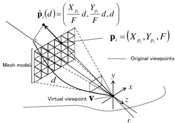
(2) 38. The International Journal of Virtual Reality, 2010, 9(1):37-44. human cost in the case of a large environment, and this makes the development of the virtualized real-world difficult. If a sufficient number of images (rays) cannot be corrected, image distortion like the unnatural aspect-ratio change of the object will be exposed on the generated images. In order to avoid the problem of holes and distortion, some methods employ a hybrid approach of IBR and MBR that employs view-dependent geometry and texture [16], [17]. Irani et al. [16] determined each pixel value of generated image by estimating the depth from the virtual viewpoint. In this method, the depth value of a pixel is automatically determined by using photo-consistency. These conventional methods that use view-dependent geometry and texture can generate natural images even if the viewpoint is set at a point far from the original viewpoint. However, on-demand depth estimation is not suitable for interactive applications like a walk-through in the virtualized real world because a considerable computational cost is incurred for each loop of the rendering stage. In this paper, we propose a novel-view synthesis method that renders free-viewpoint images using a 3-D mesh model that is deformed by considering pre-estimated depth maps for original viewpoints. In our approach, by selecting and merging appropriate depths and textures from several viewpoints, realistic images without holes can be generated even when the virtual viewpoint is set at a point away from the original viewpoint. The contributions of this paper are summarized as follows: (1) the geometry of the scene for the virtual view point can be immediately recovered by fitting a deformable mesh model to pre-estimated omnidirectional depth maps for original viewpoints, (2) the 3-D mesh model is deformed as optimal shape for the scene structure so that no holes appear in generated images, and (3) omnidirectional free-viewpoint rendering is achieved by using omnidirectional video sequences as input. The rest of this paper is organized as follows: In Section 2, the method for free-viewpoint rendering using a deformable 3-D mesh model is described. Section 3 presents experimental results for walk-through applications in the virtualized world, and finally Section 4 summarizes the present study. II.. FREE-VIEWPOINT RENDERING USING VIEW-DEPENDENT 3-D MESH MODEL. Fig. 1 shows a flow diagram of the proposed method for free-viewpoint rendering. In this research, in order to render the images for arbitrary directions in the virtualized world, input images are captured by an omnidirectional multi-camera system (OMS). By automatically tracking the feature points on the captured images, camera parameters of the OMS are estimated using the structure-from-motion algorithm designed for OMS [18]. The depth map for each input image is then estimated by multi-baseline stereo [19]. At the rendering stage, a 3-D mesh model is placed in front of the virtual viewpoint and is deformed so as to minimize an energy function that expresses consistency between the resulting view-dependent depth map and pre-estimated depth maps for original viewpoints. After deforming the mesh model,. Acquisition of input data Video capturing for target environment Camera parameter estimation By Structure from Motion Depth map generation by Multi-baseline Stereo. Free-viewpoint Rendering Generation of view-dependent 3-D model Selection of depth maps Mesh model initialization / deformation View-dependent texture mapping Selection of appropriate textures. Texture mapping. Viewpoint change by user Fig. 1. Flow diagram of proposed method.. an appropriate texture for each polygon is mapped onto the deformed mesh from the original images. 2.1 Acquisition of input data At the first stage, an omnidirectional video is taken as input data by moving an OMS in the target environment. Camera parameters of the OMS are estimated by the structure-from-motion algorithm for OMS [18]. Although not only the camera parameters but also 3-D positions of feature points can be estimated by the structure-from-motion algorithm, more dense 3-D information is necessary in order to synthesize the images for the target scene. Therefore, after estimating the camera parameters, the multi-baseline stereo algorithm for OMS [19] is applied to the input images in order to acquire the depth information for every feature point. Finally, omnidirectional dense depth maps are generated using depth interpolation. For depth interpolation, first, the 2-D feature points in omnidirectional images are triangulated by using Delaunay’s triangulation [20]. The depth value of each pixel is then determined by computing the depth for each triangle in 3-D space. The following processes use omnidirectional video, dense depth maps, and camera parameters acquired at this stage. 2.2 Generation of view-dependent 3-D model As shown in Fig. 2, before beginning the rendering stage, a 3-D mesh model is initially placed in front of the virtual viewpoint as a plane model whose distance from the virtual viewpoint is F and which is parallel to the image plane of the virtual camera. After mesh initialization, the 3-D mesh model is deformed by minimizing an energy function depending on the.
(3) The International Journal of Virtual Reality, 2010, 9(1):37-44. X p Yp pˆ i d i d , i d , d F F . Dij (d ). . pi X pi , Ypi , F. Original viewpoints. pi. e(cij , pˆ i (d )). Mesh model. y. Virtual viewpoint. x. Virtual viewpoint. v. 3-D surface acquired by depth map for c ij. pˆ i (d ). d. Original viewpoints. d. 39. v. ij (d ). z. ri ri. c ij Fig. 3. Parameters used for computing energy.. Fig. 2. 3-D coordinates of vertexes on a deformable mesh model.. position and posture of the virtual viewpoint. In the followings, the energy function that expresses the consistency of depth information is defined first. The method for selecting appropriate depth maps for computing the energy function and the method for deformation of the mesh model is then detailed. 2.2.1 Definition of energy function Each vertex on the mesh model is moved so as to minimize the energy function that expresses the consistency with the depth data of the original viewpoints. The energy is minimized when the 3-D mesh is deformed to fit the depth maps of the original viewpoints. As shown in Fig. 2, in the proposed method, destination position pˆ i of the i -th vertex p i (whose 3-D position in the camera coordinate system is ( X pi , Ypi , F ) ) in mesh deformation is constrained on the straight line connecting the virtual viewpoint v and the initial position p i . This straight line is expressed by a single parameter d in the camera coordinate system as follows.. Yp Xp (1) pˆ i (d ) i d , i d , d . F F The parameter d that expresses the depth of pˆ i in the camera coordinate system is determined by minimizing the energy E i (d ) for the i -th vertex defined as follows: Ei (d ) . . wij (pˆ i (d )) Dij (d ) 2 , jf wij (pˆ i (d )). jfi. (2). i. e(cij , pˆ i (d )) | pˆ i (d ) cij | Dij (d ) ; e(cij , pˆ i (d )) | pˆ i (d ) cij |, (3) 0 ; otherwise 1 pˆ (d ) c ij pˆ i (d ) v ij (d ) 1 arccos i | pˆ (d ) c || pˆ (d ) v | ij i i wij (pˆ i (d )) ; e(c ij , pˆ i (d )) | pˆ i (d ) c ij | , (4) 0 ; otherwise where f i ( f i1 , f i 2 ,, f iN ) represents the set of frame indexes. pi Original viewpoints. Virtual viewpoint. ci(j 1 ). ci(j 1 ). c ij. li ( j 1) lij. li ( j 1). ri Fig. 4. Selection of depth maps.. of the original viewpoints (c i1 , c i 2 ,, c iN ) that are used for computing the energy function Ei . The function e(c ij , pˆ i (d )) returns the depth value for direction pˆ i (d ) on the original viewpoint c ij , as illustrated in Fig. 3. wij (pˆ i (d )) is the weighting function for the original viewpoint c ij that is selected for the vertex pˆ i (d ) , and this function is defined as the inverse of the angle ij [degree] between two lines: the line connecting c ij to pˆ i (d ) and the line connecting v to pˆ i (d ) . As defined in Eqs. (3) and (4), the element energy Dij and its weight wij (pˆ i (d )) for the j -th original viewpoint are set to 0 if e(cij , pˆ i (d )) | pˆ i (d ) cij | . This condition is satisfied when the position pˆ i (d ) is occluded by other objects from the j -th original viewpoint c ij . It should be noted that if most of the original viewpoints satisfy the above-mentioned occluding condition, the energy Ei will be unstable because the number of original viewpoints for energy determination is very small. Therefore, the computation of energy is skipped for depth d when the number of original viewpoints that are used for energy determination is M or lower for depth d . The energy E i (d ) is minimized when the weighted sum of distances between the 3-D position pˆ i (d ) and 3-D models generated from the pre-estimated depth maps is minimized. The most consistent 3-D mesh model with a pre-estimated geometry can be automatically generated by minimizing this energy function E i (d ) ..
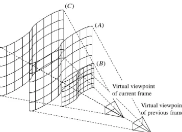
(4) 40. The International Journal of Virtual Reality, 2010, 9(1):37-44 (C ) ( A). ( A). ~p i (B). pi Virtual viewpoint of current frame. Virtual viewpoint of current frame. Virtual viewpoint of previous frame. ~ d. Fig. 6. Determination of initial depth value.. Fig. 5. Limited range for depth search.. 2.2.2 Selection of depth map As described above, the energy is computed on the basis of the depth maps of the original viewpoints. In the proposed method, as shown in Fig. 4, the depth maps used for computing the energy Ei are selected based on the distance between the original viewpoint c ij and the ray ri that connects the virtual viewpoint v and the vertex p i . Concretely, first, the Euclidian distance l ij from the ray ri to the original viewpoint c ij is computed for each j . The top N nearer original viewpoints (ci1 , ci 2 ,, ciN ) from the ray ri and their associated depth maps are then selected based on the distance l . These viewpoints are selected on the basis of the idea that there are fewer occluders between these viewpoints and the vertex p i than there are in the case of the other viewpoints. Images of the viewpoints selected in this process are also used in the texture selection process with the same reason. 2.2.3 Initialization of mesh model At the initial iteration of the rendering stage, the depth value d that minimizes the energy E i (d ) is searched in the given range [d min , d max ] . Concretely, a planar mesh model that is parallel with the image plane of the virtual viewpoint is first placed at a constant distance F from the virtual viewpoint, as shown in Fig. 2. Each vertex p i is then moved to the position pˆ i (d E min ) where the energy E i (d ) is minimized. d E min is determined as follows:. d E min argmin Ei (d ) . d min d d max. Virtual viewpoint of previous frame. (5). 2.2.4 Deformation of mesh model Except for the initial iteration of the rendering stage, the 3-D mesh model generated for the previous virtual viewpoint is used as an initial mesh model. This initial model can also be used to limit the search range for the depth value. This limitation for the depth search decreases the computational cost for a 3-D mesh deformation in each frame. Fig. 5 illustrates the limited range for the depth search when the virtual viewpoint is moved forward. The surface (A) in Fig. 5 illustrates the mesh model that is generated for the previous camera position. In the proposed. method, the search range for the depth value is limited inside the surfaces (B) and (C) that are placed around (A). Concretely, as ~ of the previously shown in Fig. 6, the intersecting point p i generated mesh model and the ray ri is first computed for the ~ i -th vertex p i . By using the depth d from the virtual ~ , viewpoint of the current frame to the intersecting point p i depth d E min is determined by using the limited search range ~ ~ [(1 Rd )d , (1 Rd )d ] as follows:. d E min . argmin [ Ei (d )] ,. ~ ~ (1 Rd ) d d (1 Rd ) d. (6). where Rd is a given ratio that determines the size of the search range. It should be noted that if occluding edges exist in the scene, this scheme cannot work well because the true depth will be outside of the search range. To avoid this problem, in the case when the minimized energy E i with the depth d E min is more than a given threshold, the depth value d is researched using Eq. (5) without a limiting the search range. 2.3 View-dependent texture mapping After deforming the mesh model, an appropriate texture image for each patch is selected and mapped to the mesh model from the images of the original viewpoints. Here, for each triangle patch on the 3-D mesh model, the frame number f , that maximizes the following function R f , is selected as the texture frame for the patch .. w (pˆ (d )) ; j f , R f kj k E min ; otherwise k jfk 0. (6). where k (k ) indicates a vertex index that constructs the patch . f k is the index list and wkj is the weighting function, which are defined in Section 2.2.1. The function R f is increased if the f -th frame is used multiple times for determining the depth of vertexes on the patch . The weight w for each viewpoint is also considered with this function. For each patch of the mesh model, the image frame that maximizes R f is selected and the image of the corresponding region in the selected image is then mapped to the patch as the texture..
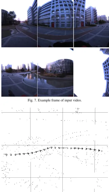
(5) The International Journal of Virtual Reality, 2010, 9(1):37-44. 41. (a) Panoramic image warped from images in Fig. 7. (b) Depth map estimated for (a) Fig. 7. Example frame of input video.. Fig. 9. Depth map used for novel view synthesis.. 1m. (b) (a). (c). Route B Virtual camera. Route C. Route A. (a) (b) (c). Original camera path. Viewpoint S. Fig. 10. Route and directions of virtual viewpoint TABLE 1: PARAMETERS USED FOR GENERATING FREE-VIEWPOINT IMAGES.. Fig. 8. Camera positions and postures used for view synthesis... III.. EXPERIMENTS. In order to verify the feasibility of the proposed method, we have carried out experiments with free-viewpoint image generation from the omnidirectional image sequences of a real outdoor environment. 3.1 Acquisition of input data In this experiment, an omnidirectional multi-camera system: Pointgrey Research Ladybug, is used in order to acquire real image sequences. Ladybug consists of six camera units for capturing an omnidirectional view; each camera unit captures a perspective video whose resolution is 7681024 pixels. Fig. 7 shows an example frame of the omnidirectional video captured in the target real environment. In this experiment, a total of 500 frames (3,000 images) are used as input video. We first estimate the extrinsic camera parameters for this video [18]. Fig. 8 shows the estimated camera position and posture of every 20 frames and the camera path for all the frames. Point clouds in this figure. Resolution of generated image Resolution of deformable mesh Number of selected depth maps: N Minimum number of depth maps: M Rate for searching-range limit: Rd. 800 800 [pixels] 31 31 5 2 0.5. indicate the 3-D positions of feature points estimated by the structure-from-motion process. By using the estimated camera positions and postures, the multi-baseline stereo method for OMS [19] is applied to the input images in order to acquire the omnidirectional depth map for each frame. Fig. 9 (a) shows the panoramic omnidirectional image generated from the images shown in Fig. 7, and (b) is the corresponding depth map acquired by the method described in Section 2.1. 3.2 Free-viewpoint rendering for straight routes First, free-viewpoint images are synthesized for three different routes, as illustrated in Fig. 10, by using the parameters shown in Table 1. (Route A) straight route in which the virtual camera moves along the original camera path..
(6) 42. The International Journal of Virtual Reality, 2010, 9(1):37-44. (Route B) straight route in which the virtual camera moves orthogonally with the original camera path. (Route C) zigzag route in which the virtual camera moves around the original camera path. For routes (A) and (B), free-viewpoint images are rendered for left (a), forward (b) and right (c) directions at intervals of 2m from the viewpoint S. Figs. 11 and 12 show the generated images for Routes A and B, respectively. In these figures, the depth maps of the generated mesh model for the direction (b) are also shown. From these results, it can be confirmed that there are no holes in the generated images. For route A, there is very little geometric distortion in the generated images. However, there exist discontinuous textures around the center of the generated images. That is mainly because of a large frame change in the texture selection for adjacent meshes. To resolve this problem, a photometric correction for textures for adjacent meshes is necessary. It should be noted that the black object shown in the bottom part of Figs. 11(a)-(c) is a handle of a camera mount; it is not directly concerning with this problem. For Route B (Fig. 12), in this scene, the images are generated without large distortions if the distance from the viewpoint S to the virtual viewpoint is 2m or shorter. However, when the distance becomes 4m or more, obvious distortion can be observed around the trees in the scene. One of the reasons of this problem is the shortage of the resolution of the mesh model. As shown in the depth maps in Fig. 12, textures on the building are mapped onto the position of the tree because of the sparse depth map. In order to solve this problem without large additional cost, employment of the adaptive mesh-division will be effective. Fig. 13 shows the generated images for Route C. In this route, 300 images are generated for the zigzag camera path moving around the original camera path. As shown in this figure, the images generated for this route are natural for most of the scene. However, distortion appears for some frames around the edges of the ground in the generated video. As shown in this figure, rippling edges that should be straight in the real world are easily perceived as unnatural by human observer. In order to reduce such an unnatural feeling with generated images, some constraints that can be extracted from the original images should be introduced to the energy function in a future work. For example, lines can easily be detected in the original images, and they can be used as constraints in mesh deformation to reduce distortions. Temporal and spatial smoothness constraint will also relax the distortion problem.. TABLE 2: COMPUTATIONAL COST FOR FREE-VIEWPOINT RENDERING.. Selection of depth map Initialization of mesh model (first time of rendering) Deformation of mesh model (except first time) Texture mapping. 1.183 0.066. system, we must implement a faster method for energy minimization like gradient descent and multi-thread programming. IV.. CONCLUSION. In this paper, we have proposed an omnidirectional free-viewpoint rendering method that uses a view-dependent 3-D mesh model. In the proposed method, a 3-D mesh model is deformed by minimizing the energy function that expresses the surface consistency with the depth maps for the original camera positions. For a deformed mesh model, appropriate textures are selected and mapped to synthesize an image of a virtual viewpoint. In experiments, free-viewpoint images are generated for several directions and positions by using omnidirectional images and depth maps. From the generated images, we have confirmed that natural images without holes are generated if the virtual viewpoint is set around the original viewpoints. However, the distortion of textures was observed in some part of the generated images. In future work, in order to improve the quality of generated images, we will investigate the method for introducing pre-detectable knowledge like straight edges in the original image as constraints on mesh deformation. Adaptive mesh-division and temporal and spatial smoothness constraint in mesh deformation will also relax the distortion problem. . ACKNOWLEDGEMENT This research was partially supported by the Ministry of Education, Culture, Sports, Science and Technology, Grant-in-Aid for Scientific Research (A), 19200016. REFERENCES [1]. 3.3 Computational cost Table 2 lists the average time for each process of the proposed method in the case when a PC (Intel Core2Duo E8600 3.33GHz, memory 16GB) is used. The rendering system uses GPU (NVIDIA GeForce GTX285, texture memory 2GB) for texture mapping and all the images are stored in the texture memory in advance. Except for the initial time of the rendering stage, we need approximately 1.3 seconds to render a single free-viewpoint image and most of the time is consumed for deforming the 3-D mesh model. This cost is due to the exhaustive search for the minimum energy within the limited range of depth. In order to realize an interactive walk-through. Average time [sec] 0.086 4.190. [2]. [3]. [4]. [5]. M. Goesele, N. Snavely, B. Curless, H. Hoppe and S. M. Seitz. Multi-view stereo for community photo collections, Proc. Int. Conf. on Computer Vision, 2007. P. Merrell, A. Akbarzadeh, L. Wang, P. Mordohai, J. M. Frahm, R. Yang, D. Nister and M. Pollefeys. Real-time visibility-based fusion of depth maps,'' Proc. Int. Conf. on Computer Vision, 2007. T. Sato, M. Kanbara, N. Yokoya and H. Takemura. Dense 3-D reconstruction of an outdoor scene by hundreds-baseline stereo using a hand-held video camera, Int. J. of Computer Vision, vol. 47, no. 1-3, pp. 119-129, 2002. Y. Furukawa, B. Curless, S. M. Seitz and R. Szeliski. Reconstructing building interiors from images, Proc. Int. Conf. on Computer Vision, pp. 80-87, 2009. C. Fruh and A. Zakhor. An automated method for large-scale, ground-based city model acquisition, Int. J. of Computer Vision, vol. 60, no. 1, pp. 5-24, 2004..
(7) 43. 4m. 2m. 0m. The International Journal of Virtual Reality, 2010, 9(1):37-44. Direction (a). Direction (b). Direction (c). Depth for (b). 4m. 2m. 0m. Fig. 11. Generated images for Route A (top: 0m, middle: 2m, bottom: 4m from viewpoint S).. Direction (a). Direction (b). Direction (c). Fig. 12. Generated images for Route B (top: 0m, middle: 2m, bottom: 4m from viewpoint S).. Depth for (b).
(8) 44. The International Journal of Virtual Reality, 2010, 9(1):37-44. Fig. 13. Generated images for Route C (Left top: First frame, Right bottom: Last frame). [6]. [7]. [8]. [9]. [10] [11] [12] [13] [14] [15]. [16]. [17]. [18]. B. J. King, T. Malisiewicz, C. V. Stewart and R. J. Radke. Registration of multiple range scans as a location recognition problem: Hypothesis generation, refinement and verification, Proc. Int. Conf. on 3D Digital Imaging and Modeling, pp. 180-187, 2005. T. Asai, M. Kanbara and N. Yokoya. 3D Modeling of outdoor environments by integrating omnidirectional range and color images, Proc. Int. Conf. on 3-D Digital Imaging and Modeling, pp. 447-454, 2005. H. Zhao and R. Shibasaki. Reconstructing a textured CAD model of an urban environment using vehicle-borne laser range scanners and line cameras, Machine Vision and Applications, vol. 14, no. 1, pp. 35-41, 2003. H. Y. Shum, S. B. Kang and S. C. Chan. Survey of image-based representations and compression techniques, IEEE Trans. on Circuits and Systems for Video Technology, pp. 1020-1037, 2003. S. E. Chen and L. Williams. View interpolation for image synthesis, Proc. SIGGRAPH’93, pp. 279-288, 1993. S. M. Seitz and C. R. Dyer. View morphing, Proc. SIGGRAPH’96, pp. 21-30, 1996. E. H. Adelson and J. Bergen. The plenoptic function and the elements of early vision, MIT press Cambridge, pp. 3-20, 1991. S. J. Gortler, R. Grzeszczuk, R. Szeliski and M. F. Cohen. The Lumigraph, Proc. SIGGRAPH’96, pp. 43-54, 1996. M. Levoy and P. Hanranhan. Light field rendering, Proc. SIGGRAPH’96, pp. 31-42, 1996. R. Sato, S. Ono, H. Kawasaki and K. Ikeuchi. Real-time image-based rendering system for virtual city based on image compression technique and eigen texture method, Proc. Int. Conf. on Pattern Recognition, 2008. M. Irani, T. Hassner and P. Anandan. What does the scene look like from a scene point? Proc. European Conf. on Computer Vision, vol. 2, pp. 883-893, 2002. A. Gupta, L. Goel, A. Kushal, P. Kalra and S. Banerjee. Super resolution of images of 3D scenes, Proc. Asian Conf. on Computer Vision, vol. 2, pp. 96-105, 2007. T. Sato, S. Ikeda and N. Yokoya. Extrinsic camera parameter recovery from multiple image sequences captured by an omni-directional. multi-camera system, Proc. European Conf. on Computer Vision, pp. 326-340, 2004. [19] T. Sato and N. Yokoya. Omni-directional multi-baseline stereo without Similarity Measures, Proc. Workshop on Omnidirectional Vision, Camera Networks and Non-classical Cameras, pp. 193-200, 2005. [20] P. Heckbert Ed. Graphics Gems IV, pp. 47-59, Academic Press, 1994. Tomokazu Sato received his B.E. degree in computer and system science from Osaka Prefecture University in 1999. He received his M.E. and Ph.D. degrees in information science from Nara Institute of Science and Technology in 2001 and 2003, respectively. He has been an assistant professor at Nara Institute of Science and Technology since 2003.. Hiroyuki Koshizawa received his B.E. degree from Kobe City College of Technology in 2007. He received his M.E. degree in information science from Nara Institute of Science and Technology in 2009. He has been working at Works Applications, Japan, since 2009.. Naokazu Yokoya received his B.E., M.E. and Ph.D. degrees in information and computer science from Osaka University in 1974, 1976 and 1979, respectively. He joined Electrotechnical Laboratory (ETL) in 1979. He was a visiting professor at McGill University in 1986-87. He has been a professor at Nara Institute of Science and Technology since 1992..
(9)
図

+4


関連したドキュメント
Furuta, Log majorization via an order preserving operator inequality, Linear Algebra Appl.. Furuta, Operator functions on chaotic order involving order preserving operator
We present and analyze a preconditioned FETI-DP (dual primal Finite Element Tearing and Interconnecting) method for solving the system of equations arising from the mortar
It is suggested by our method that most of the quadratic algebras for all St¨ ackel equivalence classes of 3D second order quantum superintegrable systems on conformally flat
We show that a discrete fixed point theorem of Eilenberg is equivalent to the restriction of the contraction principle to the class of non-Archimedean bounded metric spaces.. We
In particular, we consider a reverse Lee decomposition for the deformation gra- dient and we choose an appropriate state space in which one of the variables, characterizing the
Instead an elementary random occurrence will be denoted by the variable (though unpredictable) element x of the (now Cartesian) sample space, and a general random variable will
Keywords: continuous time random walk, Brownian motion, collision time, skew Young tableaux, tandem queue.. AMS 2000 Subject Classification: Primary:
For arbitrary 1 < p < ∞ , but again in the starlike case, we obtain a global convergence proof for a particular analytical trial free boundary method for the
