Redistribution of ionic species of the true
congruent-melting LiNbO3 with stoichiometric
structure during crystallization
著者
Shi Qilin
学位授与機関
Tohoku University
博士論文
Redistribution of ionic species of the true
congruent-melting LiNbO
3with stoichiometric
structure during crystallization
(化学量論構造を持つ真の調和融解
LiNbO
3の成長におけるイオン種分配)
Qilin Shi
施
祺霖
I
Contents
Chapter 1 Introduction ... 1
1.1 Crystal growth from LiNbO3 melt ... 1
1.1.1 Equilibrium solidification ... 5
1.1.2 Normal solidification (no diffusion in the solid and complete mixing in the liquid) ... 7
1.1.3 Normal solidification (no diffusion in the solid and partial mixing in the liquid) ... 8
1.1.4 No mixing in the liquid ... 10
1.2 Interface electric field ... 13
1.2.1 Intrinsic electric field (I): Crystallization electromotive force (c-EMF) ... 15
1.2.2 Intrinsic electric field (II): Seebeck effect ... 19
1.2.3 External electric field ... 23
1.3 Electric field-modified equilibrium partitioning coefficient, kE0 ... 23
1.4 Two types of congruent LiNbO3 ... 25
1.5 Outline of the thesis ... 30
References ... 31
Chapter 2 Effect of interface electric field on partitioning of ionic species during the growth of conventional and true congruent-melting LiNbO3 crystals ... 33
2.1 Experimental ... 33
2.1.1 Sample preparation ... 33
2.1.2 Measurement of interface electrical potential ... 33
2.1.3 Measurement of solute distribution near the interface under current injection 39 2.2 Results and discussion ... 41
2.2.1 Electric potential distribution near the solid-liquid interface during the growth of cs-MgO:LN under current injection ... 41
II
3.2.2 Current-voltage characteristics of cs-MgO:LN ... 46
2.2.3 Effect of interface electric fields on the segregation of ionic species ... 48
2.3 Summary ... 54
References ... 55
Chapter 3 Non-steady-state crystal growth of LiNbO3 in the presence of an interface electric field ... 56
3.1 Non-steady-state crystal growth from melt ... 56
3.2 Solute distribution of congruent LNs in the presence of an interface electric field 58 3.2.1 Steady-state growth ... 59 3.2.2 Non-steady-state growth ... 65 3.3 Supercooling potential ... 73 4.4 Summary ... 80 References ... 81 Chapter 4 Conclusion ... 82 Supplementary ... 84 List of Achievements ... 92 Acknowledgements ... 95
1
Chapter 1 Introduction
1.1 Crystal growth from LiNbO3 melt
LiNbO3 (LN) crystal is a ferroelectric material and belongs to the trigonal
structure, which has attracted much attention because it can be applied to non-linear optical devices due to its excellent non-non-linear optical properties [1]. It is also applied to substrates for surface acoustic wave (SAW) devices because of its low acoustic losses [2]. To obtain a single crystal with uniform compositional distribution, LN is generally grown from a congruent melt (c-LN), of which the composition is Li2O:Nb2O5 = 48.38:51.62 mol% [3].
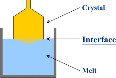
The crystallization process is a central topic for LN single crystals. During crystal growth from the melt (Fig. 1.1), it consists of three parts: bulk melt, interface and crystal. The transport and partitioning of solute occur at the interface, strongly affecting the variation of solute concentration in the crystal. Therefore, the research on the solid-liquid interface is significant. The segregation of solute is evaluated by the equilibrium partitioning coefficient k0, which is expressed as
𝑘" = $%
$&, (1.1)
where XS and XL are the mole fractions of solute in the solid and liquid in
equilibrium at a given temperature. As shown in Fig. 1.2, the degree of freedom (f) is zero at the congruent point and the equilibrium partitioning coefficient of solute is unity (𝑘"'()* = 1), that is, the solute concentration in the liquid equals that in the crystal. If k0 is not unity, the segregation of solute occurs at the solid-liquid
2 bulk melt. When 𝑘"'()* > 1, the Li
2O concentration in the solid is larger than that
in the liquid; when 𝑘"'()* < 1, the Li
2O concentration in the solid is smaller than
3
Fig. 1.1. Schematic illustration of crystal growth from the melt.
Crystal
Interface
4
Fig. 1.2. Phase diagram of Li2O–Nb2O5 around the congruent melting point [4]. Congruent point
(48.38 mol% Li2O)
5
Partitioning of solute in solidification can be divided into four limiting models, classified in Table 1.1. Take k0 < 1 for example and the details of solidification
will be discussed next.
Table 1.1 Four models of solidification [5]
1.1.1 Equilibrium solidification
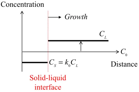
When the cooling rate is slow enough to allow the complete mixing in the solid and liquid phase, the solid and liquid phase will keep in equilibrium and always be homogeneous (Fig. 1.3). The solute concentrations in the solid, CS and the
solute concentrations in the liquid, CL at any temperature are calculated by the
lever rule.
Solidification model Solid phase Liquid phase Note
Equilibrium solidification Complete diffusion Complete diffusion Super low cooling rate Normal solidification (complete mixing) No diffusion Complete mixing Unidirectional Solidification
Normal solidification (partial mixing) No diffusion Partial mixing Czochralski method No mixing No diffusion No mixing Micro-pulling-down method
6
Fig. 1.3. Solute distribution near the solid-liquid interface under equilibrium solidification. C0 is the initial concentration in the bulk melt.
Concentration
Solid-liquid
interface
Growth
C
0Distance
C
LC
S= k
0C
L7
1.1.2 Normal solidification (no diffusion in the solid and complete mixing in the liquid)
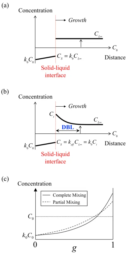
In practice, the cooling rate is rather fast and the diffusion coefficient in the solid is very small. Thus, the solute diffusion in the solid can be neglected. As shown in Fig. 1.4(a), when the complete mixing occurs in the liquid, the liquid concentration is kept homogeneous during solidification. Since the initial solute concentration in the solid is k0C0, which is lower than C0 when k0 < 1, the solid
will be purer than the liquid from which it forms so that the solute is rejected into the liquid and raises its concentration. Therefore, the mean composition of the solid is always lower than the liquid composition at the solid-liquid interface.
This complete mixing in the melt results in the maximum possible segregation (Fig. 1.4(c)). The concentration of solute in the solid with the solidification melt fraction g, is given by the Scheil equation for the complete mixing case,
8
1.1.3 Normal solidification (no diffusion in the solid and partial mixing in the liquid)
If the mixing in the liquid is not complete, the solute rejected from the solid will form a rapid buildup of solute ahead of the solid, which is called diffusion boundary layer (DBL) (Fig. 1.4(b)). The thickness of DBL is dependent on the mixing degree, ranging from 10-3 ~ 10-1 cm.
Compared with complete mixing model, this partial mixing has less segregation of solute in the solid, as shown in Fig. 1.4(c). Since the concentration in the liquid near the interface Ci, is different from the concentration in the liquid away from
the interface CL∞. The effective partitioning coefficient keff, is introduced to
evaluate the segregation of solute, given by
𝐶, = 𝑘677𝐶89(= 𝑘"𝐶:). (1.3)
Therefore, for the partial mixing case, k0 is replaced by keff in Eq. (1.2) and the
concentration of solute in the solid with the solidification melt fraction g is expressed as
𝐶, = 𝑘677𝐶"(1 − 𝑔)2;<<45. (1.4)
The relationship between k0 and keff is given by
𝑘677 = 𝑘" =>
=&?. (1.5)
9
Fig. 1.4. Solute distribution near the solid-liquid interface under normal solidification with (a) complete mixing in the liquid and (b) partial mixing in the liquid. (c) The relationship between solidified melt fraction, g and solute concentration in the solid for two models of normal solidification.
0 0
C
k
0C
Concentration
g
1
0
Complete Mixing Partial MixingConcentration
Solid-liquid
interface
Growth
CL∞ C0 CS = k0CL∞Distance
k
0C
0(a)
(b)
(c)
Ci CS = keffCL∞ = k0CiConcentration
Solid-liquid
interface
Growth
CL∞ C0Distance
k0C0DBL
10
1.1.4 No mixing in the liquid
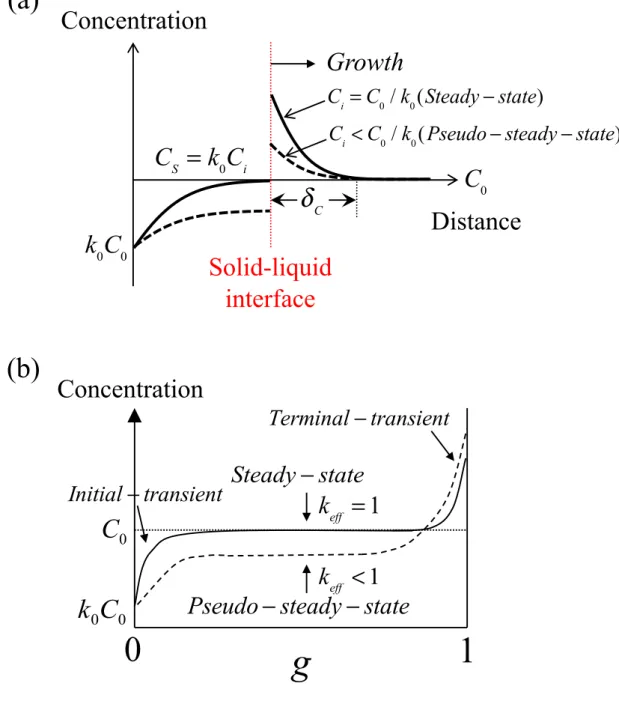
When there is no stirring or convection in the liquid phase and the solute rejected from the solid will be only transported away by diffusion, it is called no mixing solidification.
The solute distribution is shown in Fig. 1.5 (a). Initially, the concentration in the bulk melt is C0 and the solid concentration corresponds to k0C0. Thus, (C0 −
k0C0) is rejected from solid to liquid near the interface when k0 < 1. The rejected
solute is accumulated in the DBL and the concentration in the liquid away from the interface is maintained at C0, which is different from the normal solidification
in the liquid. As the crystal grows, the solute concentration in the liquid near the interface Ci gradually rises and consequently, CS (= k0Ci) also increases. When Ci
reaches C0 / k0, the solute near the interface is saturated and thus Ci will not
increase anymore. At this moment, it is regarded to reach the “steady-state” and keff = 1. However, even if keff ≠ 1, it is possible to achieve the
“pseudo-steady-state”, where Ci < C0 / k0.
We assume that the solute distribution in the liquid in one dimensional flux does not change with the time at a distance, x from the solid-liquid interface. The differential equation is written as
𝑉A=&
AB + 𝐷8 A)=&
AB) = 0, (1.6)
where V is the growth velocity and DL is the diffusion constant of the solute in the
liquid. For the no mixing model, the boundary conditions are set up as
11 and
𝐶8(B)𝑉(1 − 𝑘") + 𝐷8A=&
AB = 0 at x = 0, (1.8)
where 𝛿C is the thickness of the diffusion boundary layer. Therefore, the solute
distribution in the liquid from the interface is given as
𝐶8(B)=
=3GHIJKLMNOPQ& R5423S23GHIJOQ&T
5423S23GHIJLMQ&
. (1.9)
Combining Eq. (1.5) and Eq. (1.9), the relationship between k0 and keff is expressed
as
𝑘677 = 23
23S(5423)GHIR4JLMQ&T
. (1.10)
When k0 is unity or V is very large, keff becomes unity.
The solute distribution in the solid can be divided into “initial-transient”, “steady-state” and “transient” (Fig. 1.5 (b)). During the terminal-transient, CS performs the sharp increase due to the accumulation of solute in the
12
Fig. 1.5. Schematic illustrations of no mixing solidification for (a) solute distribution near the solid-liquid interface under and (b) the relationship between solidified melt fraction, g and solute concentration in the solid (k0 < 1).
Concentration
Solid-liquid
interface
Growth
C
0Distance
k
0C
0C
i= C
0/ k
0(Steady
− state)
C
i< C
0/ k
0(Pseudo
− steady − state)
C
S= k
0C
i(a)
0 0C
k
0C
Concentration
g
1
0
k
eff= 1
k
eff< 1
Steady
− state
Pseudo
− steady − state
(b)
Initial
− transient
Terminal
− transient
13 1.2 Interface electric field
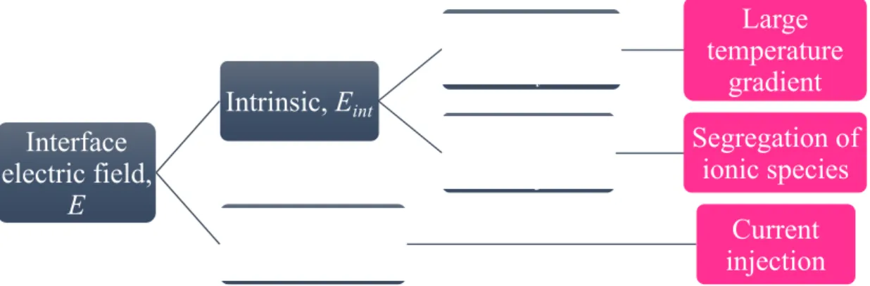
During growth of LN crystals, the interface electric field E, exists at the solid-liquid interface. As shown in Fig.1.6, it is divided into the intrinsic electric field Eint [6], composed of crystallization electromotive force (c-EMF) Ec, and Seebeck
effect Et, and the external electric field induced by current injection [7].
𝐸 = 𝐸:VW+ 𝐸6BW, (1.11)
and
14
Fig. 1.6. Schematic illustration of interface electric field.
Interface
electric field,
E
Intrinsic, E
intSeebeck effect,
E
tLarge
temperature
gradient
c-EMF,
E
cSegregation of
ionic species
15
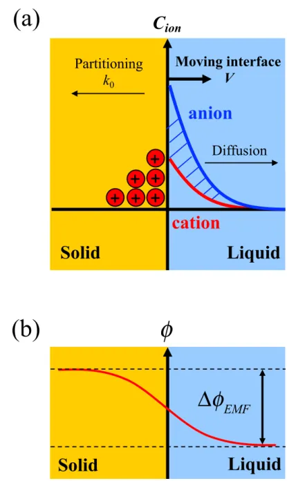
1.2.1 Intrinsic electric field (I): Crystallization electromotive force (c-EMF)
The c-EMF at the growth interface was first reported by Costa Ribeiro [8]. Since then, this electrical phenomenon was also investigated at dielectric-melt interfaces [9] and ice-water interfaces [10,11]. These studies were conducted near the room temperature until D’yakov et al. [6] reported the electric potential distribution near the solid-liquid interface during the growth of LN from a high temperature melt.
In the LN melt, both neutral and ionic species are present due to the dissociation and ionization (Fig. 1.7) [12]:
LiNbO3 ⟷ Li2O + Nb2O5, (1.13)
Li2O ⟷ Li+ + OLi−, (1.14)
Nb2O5 ⟷ Nb2O42++ O2−. (1.15)
Each species has different value for k0 and thus the net amount of anion is not
equal to the net amount cation. As shown in Fig. 1.8, the crystallization electromotive force occurs due to the net charge difference between anions and cations in the solute boundary layer as a result of segregation of ionic species [13-16]. In Fig. 1.8(b), the potential distribution near the interface is obtained by solving Poisson’s equations described as [17],
Z)[ ZB) = − \6 ] (𝐶8 ^− 𝐶 8V), (1.16)
positively-16
charged net ion and a negatively-charged net ion in the melt, zm and zn are assumed
to be equal, i.e. zm = zn = z, e is the elementary charge, 𝜀 is the dielectric constant
of the melt. It is indicated that the double integration of the total net charge distribution yields the potential due to the ionic charges near the interface in the melt, which provides the c-EMF. As a result, Ec is expressed as [14]
𝐸X = ∆𝜙cde∕ 𝛿=, (1.17)
17
Fig. 1.7. Possible forms of ionic species in the LiNbO3 melt. “ j ” represents each
constitute species including neutral and ionic species.
Solid
Liquid
LiNbO
3Nb
2O
5Li
2O
OLi
-O
2-Li
+Nb
2O
42+bulk Nb
2O
5bulk Li
2O
LiNbO3k
0
j
18
Fig. 1.8. Schematic illustrations of (a) segregation of ionic species near the solid-liquid interface and (b) generation of crystallization electromotive force (∆𝜙EMF)
during LN crystal growth. The horizontal axes show the distance from the solid-liquid interface during growth and the vertical axis shows (a) the net concentration of anion and cation and (b) the electric potential. After [9].
φ
Solid
Liquid
Δ
φ
EMF(a)
(b)
Solid
Liquid
Moving interface
V
cation
anion
C
ionDiffusion
Partitioning
k
019
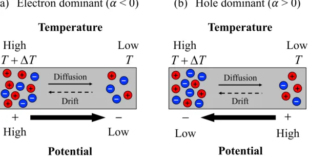
1.2.2 Intrinsic electric field (II): Seebeck effect
The Seebeck effect is described as the occurrence of an electrical potential induced by a temperature difference. When the dominant carrier in the material is the electron (Fig. 1.9(a)), electrons are active in the region of high temperature. The increasing electrons will flow from the high temperature to the low temperature to cause an electric current. When the diffusion current and drift current are in equilibrium, the net charge becomes negative in the cold side and positive in the hot side. Thus, the potential difference will be generated in the material, expressed as [14]
∆𝑉 = −𝛼 × ∆𝑇, (1.18)
where 𝛼 is the Seebeck coefficient, dependent on material and temperature and ∆T is the temperature difference. The sign of 𝛼 should be negative in Fig. 1.9(a), since the potential in the hot side is higher than that in the cold side; while the sign of 𝛼 should be positive in Fig. 1.9(b), since the potential in the hot side is lower than that in the cold side. Therefore, the sign of 𝛼 can represent the sign of dominant carrier in the material. When 𝛼 < 0, the dominant carrier is the electron (Fig. 1.9(a)); when 𝛼 > 0, the dominant carrier is the hole (Fig. 1.9(b)). It is also applied in the ionic conductors.
20
Fig. 1.9. Schematic illustrations of the occurrence of Seebeck effect in (a) electron-dominant materials and (b) hole-electron-dominant materials.
High
Low
Diffusion DriftLow
High
T
T
T
+
D
Diffusion DriftHigh
Low
T
T
T
+
D
(b) Hole dominant (! > 0)
(a) Electron dominant (! < 0)
Potential
Temperature
Potential
High
Low
21
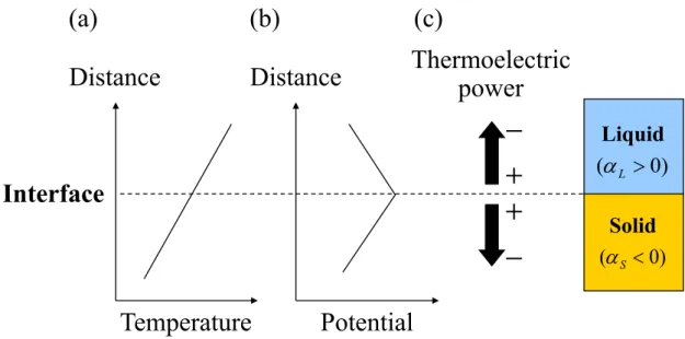
During crystal growth from the melt, the temperature in the liquid is usually higher than that in the solid and thus a temperature gradient exists at the solid-liquid interface, which will lead to the Seebeck effect. Fig. 1.10 illustrates the relationship between temperature distribution and thermoelectric power (Seebeck effect) during the growth of LN crystal. The temperature increases from solid phase to liquid phase, which indicates the existence of temperature gradient near the interface (Fig. 1.10(a)). Fig. 1.10(b) shows the interface potential distribution caused by Seebeck effect. Because the Seebeck effect in the liquid of LN is positive (𝛼L = + 0.22 mV/°C) and the Seebeck effect in the solid of LN is negative
(𝛼S = – 0.66 mV/°C) [6], the thermoelectric power in the solid and liquid is present
in the opposite direction (Fig. 1.10(c)). The Seebeck effect-driven electric field Et
is given as [14]
𝐸W = 𝛼 × 𝐺, (1.19)
where G is the temperature gradient near the interface. The electrical conduction types of individual solid LN and melt LN were studied according to the sign of the Seebeck coefficient. Bergmann [18], and Jorgensen and Bartlett [19] determined that solid LN is n-type from thermoelectric power measurements, which is supported by 𝛼S < 0. The positive sign of 𝛼L for the LN melt suggests that the
dominant carrier in the LN melt is positive and the candidate carrier is presumed to be Li+ due to its highest diffusivity among chemical species, as reported by
22
Fig. 1.10. Schematic illustrations of the occurrence of Seebeck effect in (a) electron-dominant materials and (b) hole-dominant materials.
Temperature
Distance
Potential
Interface
Solid ) 0 (a
L > ) 0 (a
S < LiquidThermoelectric
power
(a)
(b)
(c)
Distance
23
1.2.3 External electric field
In addition to the intrinsic electric field, the current injection through the interface I, can induce an external electric field Eext, in the LN melt, which shows
a linear relationship with the applied current [7],
𝐸6BW = 𝑠𝐼. (1.20)
where s is a proportional constant.
As shown in Eq. (1.11), E can be controlled by application of an external current, by which the segregation of ionic species is controlled. Nozawa et al. [17] reported the effect of electric field on the partitioning of ionic species during the growth of cs-MgO:LN and found a certain current injection cancelled the intrinsic electric field to yield zero ∆𝜙EMF. It should be also noted that the application of
an external electric field during growth also resulted in a single domain structure of an LN crystal [21-23].
1.3 Electric field-modified equilibrium partitioning coefficient, kE0
In the micro-pulling-down (μ-PD) system, the melt convection in the molten zone is very small and thus the solute boundary layer is characterized mainly by diffusion in a direction perpendicular to the growth interface [24]. Also, a large temperature gradient near the solid-liquid interface is generated in the μ-PD furnace, resulting in the Seebeck effect-driven electric field. Therefore, this method allows one-dimensional analysis for LN crystal growth under interface electric field [14].
The ion flux J, in the melt under an interface electric field by μ-PD method is written as [25]
24 𝐽 = −𝐷8A=& AB − 𝑉𝐶8+ 𝑞𝐶8 = −𝐷8 A=& AB − 𝑉c𝐶8, (1.21) where 𝑉c = 𝑉 − 𝑞. (1.22)
q is the field-driven term and VE (= V − q) is the field-modified growth velocity. q
is expressed as
𝑞 =o&\6c
2pq , (1.23)
where kB is the Boltzmann constant and T is the absolute temperature.
Because the diffusion constant of the ionic species in the solid DS, is small
enough to be neglected, the interface conservation condition for zero diffusion in the solid [12] 𝑉(1 − 𝑘")𝐶: = −𝐷8A=AB&+ 𝑞𝐶:, (1.24) is converted into 𝑉c(1 − 𝑘c")𝐶: = −𝐷8A=& AB, (1.25) where
25 𝑘c" = 𝑘"rr
s. (1.26)
Therefore, when the interface electric field operates on the solid-liquid interface during crystal growth, k0 is replaced by the electric field modified equilibrium
partitioning coefficient kE0, dependent on the growth velocity and interface electric
field. Here, kE0 is experimentally obtained by measurement of the solute
concentration ratio between solid and liquid at the interface, and is described as
𝑘c" = =%
=>. (1.27)
1.4 Two types of congruent LiNbO3
For known congruent LNs with or without dopants, such as c-LN (Fig. 1.11(a)) and c-ZnO:LN (2.5 mol% ZnO-doped LN) [17], the congruent point does not coincide with the stoichiometric point. In this case, we have clarified that the equilibrium partitioning coefficient k0, of all the constituent elements, including
ionic species, is not unity [13], although the k0s of the net components, LivO,
NbvOz and ZnO are unity. Here, we have extended the concept of stoichiometry
such that a material is stoichiometric if the activities of all the constitute elements can be unity [13,26,27]. We have previously reported that doping of 4.7 mol% MgO into LN with 50 mol% Nb2O5 enables it to be simultaneously stoichiometric
and congruent, which is denoted as cs-MgO:LN (Fig. 1.11(b)) [13]. The k0 of all
chemical components of cs-MgO:LN is unity and thus all of their activities are unity, which is then defined as true congruent-melting LN [26]. Therefore, no segregation of any ionic species is expected to occur during the growth of cs-MgO:LN [13]. In contrast, c-LN is a conventional congruent-melting LN, where
26
the k0 of net LivO and net NbvOz are unity but the k0 of the ionic species are not
27
Fig. 1.11. (a) Li2O–Nb2O5 binary phase diagram around LN (after [13]). LN has a
wide solid solution range and its congruent composition does not coincide with the stoichiometric composition. (b) Li2O–Nb2O5–MgO pseudo-ternary phase
diagram around cs-MgO:LN (after [28]). 1200 46 48 50 600 1400 LiNbO3 + LiNb3O8 LiNbO3 + Li3NbO4 Li2O/mol% T em pe rat ur e/ ˚C
LiNbO
3 800 1000 (Nb2O5) (Li2O)c-LN
s-LN
(a)
(b)
cs-MgO:LN
2 1s-LN
Li
2O
Nb
2O
5 6 5 4 3 50 48 49 47 46mol% Li
2O
m
ol
% M
gO
c-LN
7MgO
“
Stoichiometric line
”
of Nb
2O
5(50mol%)
28
Kimura and Uda [13] evaluated the c-EMFs of c-LN, s-LN, and cs-MgO:LN to be 5.3, 8, and 0 mV, respectively, at the zero temperature gradient at the interface, which is obtained by extrapolation from measurements at several different temperature gradients of c-EMF into a 0 °C/cm temperature gradient (Fig. 1.12). The zero temperature gradient means that there is no Seebeck effect-driven electric field, but only the c-EMF-induced electric field remains. Zero c-EMF for the growth of cs-MgO:LN is obtained when the temperature gradient is zero, which indicates that no segregation of ionic species occurs at the interface, while non-zero c-EMFs for other LNs indicate that segregation occurs, even at the non-zero temperature gradient.
LN crystals can be easily grown from the congruent melts-LN. However, the optical properties of c-LN, like photoconductivity and transparency in the short wavelength region, are inferior to those of s-LN [29]. Therefore, this true congruent LN, cs-MgO:LN will perform better optical properties to the conventional c-LN and s-LN.
29
Fig. 1.12. Temperature-gradient dependence of for s-LN, c-LN, and cs-MgO:LN (after [13]). Dashed line for cs-MgO:LN represents extrapolation to zero temperature gradient. Parallels to those lines are assumed for s-LN and c-LN.
0
2
4
6
8
10
12
0
400
800
1200
1600
2000
∆
!
EMF
(mV)
Temperature gradient (°C/cm)
s-LN
c-LN
cs-MgO:LN
30 1.5 Outline of the thesis
To obtain highly uniform LN single crystals, the redistribution of ionic species for conventional (c-LN, c-ZnO:LN) and true (cs-MgO:LN) congruent LNs in the presence of interface electric field is investigated. This thesis focuses on the mechanism of the LN single crystal growth from melt by taking the interface electric field into account. The effect of interface electric field on the segregation of ionic species was evaluated by the crystallization electromotive force (c-EMF) and the electric field-modified equilibrium partitioning coefficient, kE0.
This thesis contains four chapters, which are outlined as follows: In chapter 1, the background and objective of the thesis are presented.
In chapter 2, the distribution of electric potential at the solid-liquid interface under different external electric fields is studied. The difference in partitioning of ionic species between c-ZnO:LN and cs-MgO:LN is compared.
In chapter 3, the non-steady-state growth of LN is conducted by using the μ-PD technique. The effect of an abrupt change in the growth velocity on compositional variation in grown crystals under different external currents is investigated, and the effect of the velocity dependence of supercooling is also discussed.
31 References
[1] R.S. Weis, T.K. Gaylord, Appl. Phys. A 37 (1985) 191.
[2] T. Volk, M. Wöhlecke. Lithium niobate: defects, photorefraction and ferroelectric switching. Springer Science & Business Media, 2008.
[3] P. F. Bourdi, R. G. Norwood, C. D. Bird, G. D. Calvert, J. Cryst. Growth 113 (1991) 61.
[4] LO. Svaasand, M. Eriksrud, G. Nakken, AP. Grande, J. Cryst. Growth 1974, 22:179.
[5] 宮澤信太郎 著, 共立出版株式会社 結晶成長のダイナミクス第 5 巻, メ
ルト成長のダイナミクス.
[6] V.A. D’yakov, D.P. Shamov, L.N. Rashkovich, A.L. Aleksandrovskii, Bull. Acad. Sci. USSR, Phys. Ser. 49 (1985) 117
[7] S. Uda, T. Tsubota, J. Cryst. Growth 312 (2010) 3650. [8] J.C. Ribeiro, Anis Acad. Brasil. Cienc. 17 (1945) 3.
[9] S. Mascarenhas, L.G. Freitas, J. Appl. Phys. 31 (1960) 1684. [10] E.J. Workman, S.E. Reynolds, Phys. Rev. 78 (1950) 254. [11] B.K. Jindal, W.A. Tiller, Surface Science 9 (1968) 137. [12] S. Uda, W.A. Tiller, J. Cryst. Growth 121 (1992) 155. [13] H. Kimura, S. Uda, J. Cryst. Growth 311 (2009) 4094. [14] Y. Azuma, S. Uda, J. Cryst. Growth 306 (2007) 217.
[15] A.L. Aleksandrovskii, D.P. Shumov, Cryst. Res. Technol. 25 (1990) 1239. [16] S. Koh, S. Uda, M. Nishida, X. Huang, J. Cryst. Growth 297 (2006) 247. [17] J. Nozawa, S. Iida, C. Koyama, K. Maeda, K. Fujiwara, S. Uda, J. Cryst.
Growth 406 (2014) 78.
[18] G. Bergmann, Sol. State Commun. 6 (1968) 77.
32
[20] W.A. Tiller, S. Uda, J. Cryst. Growth 129 (1993) 341.
[21] K. Nassau, H.J. Levinstein, G.M. Loiacono, Appl. Phys. Lett. 6 (1965) 228. [22] K. Nassau, H.J. Levinstein, Appl. Phys. Lett. 7 (1965) 69.
[23] K. Nassau, H.J. Levinstein, G.M. Loiacono, J. Phys. Chem. Solids 27 (1966) 989.
[24] S. Uda, J. Kon, K. Shimamura, T. Fukuda, J. Crystal Growth 167 (1996) 64. [25] S. Uda, J. Kon, J. Ichikawa, K. Inaba, K. Shimamura, T. Fukuda, J. Cryst.
Growth 179 (1997) 567.
[26] S. Uda, “Stoichiometry of oxide crystals,” in Handbook of Crystal Growth: Fundamentals, 2nd ed., edited by T. Nishinaga (Elsevier, 2014), Vol. IA, Chap. 4.
[27] S. Uda, J. Cryst. Growth 310 (2008) 3864.
[28] H. Kimura, T. Taniuchi, S. Iida, S. Uda, J. Cryst. Growth 312 (2010) 3425. [29] Y. Furukawa, K. Kitamura, S. Takekawa, Opt. Lett. 23 (1998) 1892.
33
Chapter 2 Effect of interface electric field on partitioning of
ionic species during the growth of conventional and true
congruent-melting LiNbO
3crystals
In Chapter 2, two types of congruent-melting LNs, conventional and true, were surveyed in association with the partitioning of ionic species. We investigated the segregation of ionic species for true and conventional congruent-melting LNs grown via the μ-PD method under various interface electric fields. A non-ohmic contact between the LN melt and crystal is also shown by surveying the current-voltage characteristics, which suggests a Schottky contact similar to a metal (melt)-n type semiconductor (LN crystal) junction.
2.1 Experimental
2.1.1 Sample preparation
Li2CO3, Nb2O5 and dopant (MgO and ZnO) powders (99.99% purity) were
prepared. Li2CO3 was dried at 400 °C for 10 h, while Nb2O5 and dopants were
dried at 1000 °C for 10 h. After drying, Li2CO3, Nb2O5, MgO and ZnO were
weighed and completely mixed with the true congruent-melting composition (Li2O:Nb2O5:MgO = 45.3:50.0:4.7 mol%, denoted as cs-MgO:LN [1]) and the
conventional congruent-melting composition (Li2O:Nb2O5:ZnO = 46.5:51.0:2.5
mol%, denoted as c-ZnO:LN [2]). The mixtures were sintered at 1100 °C for 4 h and the products were then ground into powders. The products were sintered and crushed repeatedly until reacted completely.
2.1.2 Measurement of interface electrical potential
The c-EMF measurement was conducted via the μ-PD furnace shown in Fig. 2.1. The μ-PD furnace consists of a Pt crucible (15 mm × 12 mm × 0.3 mm) with
34
a Pt capillary nozzle (⌀d = 1 mm, l = 2 mm). Uda et al. [3] showed the Mn
distribution in LN fiber crystals with different diameters by the μ-PD method under an interface electric field. The radial Mn distribution was observed to be homogeneous with ⌀d larger than 0.8 mm under GL = 4000 °C/cm. Therefore,
one-dimensional analysis is allowed along the c-axis direction when a crystal with 1.0 mm ⌀d is grown with a growth velocity of 5 mm/h. Growth of this type of fiber
crystal with a diameter of 1 mm or less is typically accompanied by a large temperature gradient near the interface with the μ-PD method. In our experiment the interface temperature gradient in the liquid, GL, near the interface was
measured to be around 1000 °C/cm. These are the growth conditions that were employed in the present experiments, and the Seebeck effect-driven electric field Et, was then ca. 220 mV/cm. The LN material was melted by application of 50 Hz
AC power through the Pt crucible, which also acted as a resistance heater. Two thermocouples (TC1 and TC2: ⌀d = 0.1 mm, Pt/Pt-13%Rh) were placed into the
crucible to measure the temperature (T1 and T2) and the electrical potential
difference, ∆𝜙 = ∆𝜙q) − ∆𝜙q~, between T1 and T2. TC1 was fixed in the melt, while TC2 moved with the fiber crystal. A large temperature gradient existed near
the solid-liquid interface during growth, which yielded the Seebeck effect-driven intrinsic electric field. To modify this intrinsic electric field, a DC current was supplied to the system through the two thermocouples as electrodes. This was addressed as forward when the current flowed from the crystal to the melt, while it was reverse when the current flowed from the melt to the crystal. The LN melt and the interface solid are electrically very conductive at the melting temperature; therefore, there is a small electrical potential difference along the radial direction where we assume a radial isotherm. Therefore, the melt where the thermocouple is situated can serve as a plate electrode and the solid near the interface also serves
35
as a plate electrode. Therefore, the current acts on the entire area of the cross section of the melt between TC1 and TC2.
The measurement started with two thermocouples being in the melt (stage 1). TC2 was pulled down along the nozzle at a constant velocity of 5 mm/h and went
through the liquid-solid interface (stage 2) to enter the solid phase completely. The pulling down process was then stopped (stage 3 to stage 4). After a 5 min halt, TC2
was pulled up in the opposite direction until it went back to the initial position in the melt (stage 4 to stage 6). A Δ𝜙-T2 curve was recorded during this entire
36
Fig. 2.1. Schematic illustration of the μ-PD furnace. The potential difference (Δ𝜙) is measured with or without application of a DC current during the process of pulling down (growth, stage 1 to stage 3), halt (stage 3 to stage 4) and subsequent pulling up (melting, stage 4 to stage 6) [4].
1 mm Melt Capillary nozzle 2 mm Fiber crystal TC2(mobile) Pt crucible TC1(fixed) Voltmeter ∆!= !2−!1 T2 T1 1 6 3 4 2 5
Pull down Pull up
Halt
DC power Δφ= Δφ T2− ΔφT1
37
The current-voltage characteristics were examined to investigate the electrical behavior at the boundary between the LN crystal and LN melt in the cs-MgO:LN system (Fig. 2.2). After the crystal grew to a length of 3 mm, pulling down was stopped. Various voltages (DC power) were then applied to the interface through two Pt wires (0.1 mm ⌀d) and the current was recorded continuously with an
38
Fig. 2.2. Schematic illustration of the setup for measurement of the current-voltage characteristics at the solid-liquid interface of the LN crystal and LN melt.
Melt
Fiber
crystal
Pt wire
Pt crucible
Pt wire
DC power
(Voltage)
3 mm
A
Melt-crystal interface
39
2.1.3 Measurement of solute distribution near the interface under current injection
Two types of congruent LNs, true congruent-melting LN (cs-MgO:LN) and conventional congruent-melting LN (c-ZnO:LN) were used to investigate the partitioning and segregation of ionic species during growth via μ-PD. External currents (−1.0 to +0.2 mA, current density: −128 to +26 mA/cm2) were applied
during crystal growth. Ridges with threefold symmetry appeared in the steady-state growth, which illustrates that a single crystal was grown along the c-axis. When a crystal grew to a length of 3 mm, which was sufficiently long to reach steady-state, the AC power was shut down to freeze the solute distribution near the solid-liquid interface. After quenching, the crystal, together with the nozzle part to maintain the solid-liquid interface, was cut from the crucible (Fig. 2.3). The distribution of Mg and Zn near the interface was then measured by electron probe microanalysis (EPMA) along the central growth axis and the kE0s were then
determined. Because Li in the LiNbO3 crystals is too light to be detected by EPMA,
the total content of the other elements (i.e., Nb, O, and Mg for cs-MgO:LN (Li2O:Nb2O5:MgO = 45.3:50.0:4.7 mol%) or Nb, O, and Zn for c-ZnO:LN
(Li2O:Nb2O5:ZnO = 46.5:51.0:2.5 mol%)) was normalized to 100 wt%; thus, 0.804
wt% for Mg corresponds to 4.7 mol% Mg, and 1.127 wt% for Zn corresponds to 2.5 mol% Zn.
40
Fig. 2.3. Quenched LN single crystal near the interface of solid and liquid.
Liquid
Solid
41 2.2 Results and discussion
2.2.1 Electric potential distribution near the solid-liquid interface during the growth of cs-MgO:LN under current injection
When a current is applied to the growth system, a current-induced electric field is generated near the solid-liquid interface, which modifies the intrinsic electric field and influences the transport and partitioning of ionic species, and results in a change of the c-EMF. Fig. 2.4(a) shows Δ𝜙-T2 curves at different applied
currents ranging from −0.5 to +0.3 mA (current density: −64 to +38 mA/cm2).
During the growth, halt, and melting processes, the Δ𝜙-T2 value showed a
clockwise hysteresis when the applied current was changed from +0.3 to −0.1 mA, while it showed an anti-clockwise hysteresis for applied currents larger than −0.1 mA. Such a hysteresis, ∆𝜙hys, varies with the applied current and has a relationship
with c-EMF shown by [2]
∆𝜙•€• = Δ𝜙cdeƒ„…†W•− Δ𝜙cde^6‡W:Vƒ ≈ 2∆𝜙cde, (2.1)
where Δ𝜙cdeƒ„…†W• and Δ𝜙cde^6‡W:Vƒ denote the c-EMF during the growth and melting processes, respectively, and they have almost the same absolute value but opposite signs. It should be noted that the hysteresis disappears at −0.1 mA or −13 mA/cm2
in terms of current density, which represents ∆𝜙EMF = 0 at this current. This is the
critical current, denoted as Ic. In the case of cs-MgO:LN growth,the external field
induced by Ic completely counters the intrinsic electric field, so that there is no
interface electric field present and the kE0 of all ionic species return to k0 (= 1), by
which there is no segregation of the ionic species. However, this is not the case of the conventional congruent-melting c-ZnO:LN, although there is a certain applied
42
current that makes the net amount of anions equal to those of cations, which leads to zero c-EMF. Here we calculate the external electric field Eext, induced by Ic,
taking the resistivity of the LN melt, 𝜌L (= 14.5 Ω cm). The calculated Eext is ca.
185 mV/cm, which is almost the same as the Seebeck-effect induced electric field of 220 mV/cm. When I > Ic, the number of net anions is more than that of net
cations at the interface in the melt during the growth process, while the sign of the total net ions changes from negative to positive during the melting process. As a result, Δ𝜙cdeƒ„…†W• > 0 and Δ𝜙cde^6‡W:Vƒ < 0; therefore, ∆𝜙hys > 0 and ∆𝜙EMF > 0.
However, when I < Ic, the net cations and net anions in the melt near the interface
are distributed in the opposite manner during growth and melting, which leads to ∆𝜙hys < 0 and ∆𝜙EMF < 0.
Here, the variation of the slope in the Δ𝜙-T2 curve under different current
injection is discussed. The value of the slope for the liquid and solid generally represents the Seebeck coefficient (𝛼L and 𝛼S) when there is no current injection.
However, once a current is applied to induce an external field, the slopes (S) of the Δ𝜙-T2 curve for the liquid and solid phases no longer simply represent the
Seebeck coefficients, not only because of the temperature difference, but also the external current, which modifies the potential in the liquid and solid phases. The slope for the liquid, SL, (shaded region in the Fig. 2.4(a)) changes from positive to
negative as the applied current is increased.
The change of the slope is due to the LN melt being a resistor and the imposed current of +0.3 to −0.5 mA generating an extra electrical potential, which results in an external field Eext, as large as +510 to −850 mV/cm in the liquid phase. When
the direction of the current changes from forward to backward, the corresponding sign of the induced electric potential changes from positive to negative. The values of the slopes for the liquid phase are presented in Fig. 2.4(b), which shows a linear
43
relationship with the applied current and indicates an ohmic contact between the melt and the electrode. This will be also shown in Fig. 2.5(a). The total Δ𝜙 in the liquid, which is composed of the potentials caused by the Seebeck-effect and external current, is expressed as [6]
∆𝜙 = 𝛼8(𝑇5− 𝑇v) + Δ𝜙X•„„6VW8 , (2.2)
where Δ𝜙X•„„6VW8 is the electric potential induced by current injection, which is
calculated using Eqs. (2.3) and (2.4), for the liquid phase as
Δ𝜙X•„„6VW8 = 𝐼𝜌
8‡Ž&, (2.3)
Δ𝜙X•„„6VW8 = 𝐼𝜌 8qŽ•~4q)
& , (2.4)
where I is the applied current, lL is the distance between TC1 and TC2 in the melt,
and A is the cross section of the nozzle. Combining Eq. (2.2) with Eq. (2.4) gives
∆𝜙 = (𝑇5− 𝑇v) •𝐼 ‘&
Ž•&+ 𝛼8’. (2.5)
Therefore, the slope of Δ𝜙 in the liquid SL, is derived as Eq. (2.6),
𝑆8 =q∆[ ~4q)= 𝐼
‘&
Ž•&+ 𝛼8. (2.6)
44
with the experimental results presented in Fig. 2.3(b).
In contrast to the liquid case, the slope in the solid phase (clear region in Fig. 2.4(a)) SS, remains almost constant under the imposed reverse current (smaller than
0 mA), and it increases sharply at currents larger than 0 mA. The relation between SS and the applied current is plotted in Fig. 2.4(c), which indicates the non-linear
dependence of the potential on the current. The total Δ𝜙, which includes the liquid and solid phases, is expressed as [2]
∆𝜙 = 𝛼8(𝑇5− 𝑇:) + 𝛼,(𝑇: − 𝑇v) + ∆𝜙X•„„6VW8 + ∆𝜙
X•„„6VW, + Δ𝜙cde, (2.7)
where Ti is the interface temperature, ∆𝜙EMF is the c-EMF determined by the
intrinsic electric field and the applied-current induced electric field, and ∆𝜙X•„„6VW,
is the electric potential induced by current injection in the solid, as expressed by Eq. (2.8):
∆𝜙X•„„6VW, = ”
Ž∫ 𝜌,(𝑙)𝑑𝑙 ‡%
" , (2.8)
where 𝜌,(𝑙) is the resistivity of the LN crystal and lS is the distance between the
interface (Ti) and TC2 in the solid. The Seebeck-effect driven potential,
current-induced potential in the solid, and c-EMF are taken into account to obtain the total Δ𝜙. The relation between SS and I obtained for the solid represents not a simple
linear curve, but shows the non-linear dependence of the potential on the applied current in the solid. We consider this LN melt-LN crystal circuit to be a rectifying contact, the details of which will be discussed next.
45
Fig. 2.4. (a) Δ𝜙-T2 curve during growth and melting process of cs-MgO:LN under
various applied currents. The left shaded region and the right clear region represent those for the potential difference, Δ𝜙 (= ∆𝜙q)− ∆𝜙q~) for the liquid and solid phases, respectively. The slopes for the liquid and solid are denoted as SL and SS.
The growth velocity was 5 mm/h. The slopes of the Δ𝜙-T2 curves are plotted as a
function of the applied current (b) in the liquid and (c) in the solid. After [5].
Solid Liquid (a) Down Up Δφhys SS SL ∆ ! (mV) T2( C) +0.3 mA +0.2 mA 0 mA −0.1 mA −0.3 mA 0.0 mA -1.0 -0.5 0.0 0.5 1.0 1.5 -0.6 -0.4 -0.2 0 0.2 0.4 S lop e of p ote n ti al in th e li q u id , SL (mV / C )
Applied current (mA) (b) -2 0 2 4 6 8 -0.6 -0.4 -0.2 0 0.2 0.4 S lop e of p ote n ti al in th e sol id , SS (mV / C )
Applied current (mA) (c)
46
3.2.2 Current-voltage characteristics of cs-MgO:LN
Previous works discussed the electrical conduction type of LN crystal; however, they did not consider the contact between the LN crystal and LN melt.
Fig. 2.4(c) implies that it is not a simple ohmic contact between the LN crystal and LN melt that serves as an electrode. The current-voltage characteristics were surveyed to understand the electrical characteristics of the boundary between LN crystal and melt. First, an ohmic contact of metal (Pt)−LN melt was confirmed by the linear dependence of the current on the applied voltage in Fig. 2.5(a). In contrast, Fig. 2.5(b) showed a Schottky barrier on an n-type semiconductor of cs-MgO:LN crystal, where cs-cs-MgO:LN melt served as a metal with some resistivity in the measurement. The reason is that when a positive voltage was applied to the solid-liquid interface of cs-MgO:LN via the melt the current exponentially increased, whereas the current was almost constant with a negative voltage. The relation between voltage and current is similar to that of a Schottky contact, which typically appears in metal-semiconductor junctions.
47
Fig. 2.5. Current-voltage characteristics for (a) an ohmic contact of cs-MgO:LN melt and (b) a Schottky barrier on an n-type semiconductor of cs-MgO:LN crystal. After [5].
(a)
-30
-20
-10
0
10
20
30
-1.5
-1
-0.5
0
0.5
1
1.5
C
u
rr
en
t (mA
)
Voltage (V)
-2
0
2
4
6
8
10
12
14
-1.5
-1
-0.5
0
0.5
1
1.5
C
u
rr
en
t (mA
)
Voltage (V)
(b)
48
2.2.3 Effect of interface electric fields on the segregation of ionic species
Ionic species are present in the LN melt and the interface electric field affects the partitioning of these species. During the growth of true congruent-melting cs-MgO:LN with a growth velocity of 5 mm/h, the Mg distributions near the interface with applied currents of 0, −0.1 and −1.0 mA (current density: 0, −13 and −128 mA/cm2) were obtained via EPMA measurements (Fig. 2.6). Fig. 2.6(a) shows the
Mg distribution at 0 mA, where only the intrinsic electric field was effective. Here, CS is determined as the average concentration in the range of a 0.1 mm length in
the steady-state region of the grown crystal, which was determined to be 0.81 wt%. The concentration in the melt at the interface (indicated by the dashed line in Fig. 2.6(a)) is termed Ci and this was 0.66 wt%. From CS and Ci, kE0 is determined to
be 1.23, which is larger than unity. Without an applied electric field, Mg segregation occurs near the interface. In a similar way, Mg distributions with applied currents of −0.1 mA and −1.0 mA were obtained, as shown in Figs. 2.6(b) and (c), respectively. kE0 also decreased as the reverse current was increased. In
particular, when a reverse current of I = −0.1 mA was imposed, the Mg distribution became uniform (Fig. 2.6(b)), even near the interface. This is the critical current Ic, where kE0 becomes unity and thus kE0 = k0 = 1. When the reverse current is
smaller than Ic, Ci is larger than Cs, which leads to kE0 < 1 (Fig. 2.6(c)). Therefore,
the partitioning of Mg concentration can vary such that kE0 > 1, kE0 = 1 and kE0 <
49
Fig. 2.6. Distribution of Mg concentration near the solid-liquid interface during the growth of a cs-MgO:LN crystal at a growth velocity of 5 mm/h; (a) kE0 > 1 at
0 mA, (b) kE0 = 1 with a reverse current of −0.1 mA, and (c) kE0 < 1 with a reverse
current of −1.0 mA. After [5].
0.4 0.5 0.6 0.7 0.8 0.9 1.0 -0.03 -0.02 -0.01 0 0.01 0.02 0.03 M g ( wt %)
Distance from interface (mm)
Interface Solid Liquid (a) CS Ci 0.4 0.5 0.6 0.7 0.8 0.9 1.0 -0.03 -0.02 -0.01 0 0.01 0.02 0.03 M g ( wt %)
Distance from interface (mm)
Interface Solid Liquid (b) 0.4 0.5 0.6 0.7 0.8 0.9 1.0 -0.03 -0.02 -0.01 0 0.01 0.02 0.03 M g ( wt %)
Distance from interface (mm)
Interface
Solid Liquid
50
For the conventional congruent c-ZnO:LN, of which the congruent point does not coincide with the stoichiometric structure, kE0 and ∆𝜙EMF are plotted in Fig.
2.7(a) as a function of the applied current (0 to −1.0 mA; 0 to −128 mA/cm2) at a
growth velocity of 5 mm/h. When the current was smaller than −1.0 mA, oxygen bubbles were generated at the interface, which disturbed the normal crystal growth. The black circles denote the values of kE0 for Zn as a function of the applied current
and the red diamonds indicate the c-EMF. It was determined that ∆𝜙EMF = 0 at
−0.2 mA, whereas kE0 for Zn is not unity. This Zn distribution near the solid-liquid
interface under ∆𝜙EMF = 0 is shown in Fig. 2.7(b). It is thus clear that kE0 is not
unity though ∆𝜙EMF = 0 for conventional congruent-melting c-ZnO:LN. This
indicates that k0 for all species of c-ZnO:LN is not unity and zero EMF only occurs
51
Fig. 2.7. (a) Variation of kE0 for Zn and ∆𝜙EMF as a function of the current applied
to c-ZnO:LN at a growth velocity of 5 mm/h. The value of ∆𝜙EMF is zero at −0.2
mA. (b) Distribution of Zn concentration near the solid-liquid interface during the growth of a c-ZnO:LN crystal with ∆𝜙EMF = 0 (growth velocity: 5 mm/h, applied
current: −0.2 mA). After [5].
k
E0 -1.0 -0.5 0.0 0.5 1.0 1.5 2.0 2.5 3.0 1.25 1.30 1.35 1.40 1.45 1.50 1.55 -1.1 -0.9 -0.7 -0.5 -0.3 -0.1 0.1∆
!
EM F(mV
)
Applied current (mA)
kE0 EMF
Δ
φ
EMFk
E 0Zn(a)
0.3 0.5 0.7 0.9 1.1 1.3 1.5 -0.06 -0.04 -0.02 0 0.02 0.04 0.06Zn
(
wt
%)
Distance from interface (mm)
Solid
Liquid
Interface
(b)
52
Next, the relation between kE0 and the applied current (+0.2 to −1.0 mA; +26
to −128 mA/cm2) for the true congruent-melting cs-MgO:LN was investigated in
a similar way. The results were different from that for the conventional congruent-melting c-ZnO:LN. Fig. 2.8(a) shows kE0 for Mg and ∆𝜙EMF as a function of the
applied current. The growth velocity was 5 mm/h. The profile of kE0 for Mg was
analogous to that for Zn; however, kE0 =1 occurs simultaneously with ∆𝜙EMF = 0
at Ic = −0.1 mA. Without current injection, q in Eq. (1.23) is only due to the
intrinsic electric field, and q > 0, VE = V − q < V; therefore, V/VE > 1 and kE0 > k0
= 1. With a forward current imposed, q increases and VE becomes smaller and close
to 0, which leads to a rapid increase of kE0. In the case of a reverse current, q
gradually decreases until q = 0, which is attained at I = Ic (= −0.1 mA). At this
point, VE = V and kE0 = k0 =1. When q is negative for I < Ic, VE > V, and thus, V/VE
< 1 and kE0 < k0 = 1. In our previous work [2], zero c-EMF of cs-MgO:LN was
achieved at any growth velocity under Ic, and it was expected that kE0 was unity
and equivalent to k0. To experimentally confirm this, kE0 for Mg was investigated
under different growth velocities with Ic (= −0.1 mA). Fig. 2.8(b) shows that kE0 =
1 and is equivalent to k0 (= 1) at any growth velocity for cs-MgO:LN when an Ic
53
Fig. 2.8. (a) Variation of kE0 for Mg and ∆𝜙EMF as a function of the current applied
to cs-MgO:LN at a growth velocity of 5 mm/h. The value of ∆𝜙EMF is zero at −0.1
mA, where kE0 is also unity. (b) Variation of kE0 for Mg as a function of the growth
velocity, where I = Ic = −0.1 mA was imposed. kE0 is unity, regardless of the growth
velocity, which leads to ∆𝜙EMF = 0. After [5].
-3 0 3 6 9 12 15 0.90 1.00 1.10 1.20 1.30 1.40 1.50 1.60 -1.1 -0.9 -0.7 -0.5 -0.3 -0.1 0.1 0.3
∆
!
EM F(mV
)
kE0Applied current (mA)
kE0 ∆!EMF/mV
Δ
φ
EMFk
E0Mg(a)
k
E0 0.80 0.90 1.00 1.10 1.20 0 5 10 15 20 25 30 35 40 45k
E0Growth velocity (mm/h)
(b)
k
E0I
= I
c= −0.1mA
54 2.3 Summary
The effect of the interface electric fields comprised of intrinsic and external interface electric fields on the segregation of ionic species was investigated for the growth of two types of congruent LNs via the μ-PD method, conventional congruent-melting c-ZnO:LN and true congruent-melting cs-MgO:LN. An external current was applied to modify the intrinsic electric field. The electric potential distribution near the solid-liquid interface was surveyed under various current injection conditions, and the generation of a crystallization electromotive force (c-EMF) and thermoelectric power due to the high temperature gradient around the interface was investigated. These phenomena caused an increase of the intrinsic electric field at the interface, which was modified by the external electric field induced by current injection. The interface electric field modified the distribution and partitioning of ionic species near the interface for the c-ZnO:LN and cs-MgO:LN systems. During the growth of cs-MgO:LN, kE0 for Mg became
unity and ∆𝜙EMF = 0, regardless of the growth velocity at I = Ic, while kE0 for Zn
was not unity, even when ∆𝜙EMF = 0. This confirms that k0 for all melt chemical
species is unity for true congruent-melting LN, which is simultaneously stoichiometric and congruent. The boundary between liquid LN and solid LN was also determined to be a Schottky contact, which implies a metal-n type semiconductor junction of LN.
55 References
[1] H. Kimura, S. Uda, J. Cryst. Growth 311 (2009) 4094.
[2] J. Nozawa, S. Iida, C. Koyama, K. Maeda, K. Fujiwara, S. Uda. J. Cryst. Growth 406 (2014) 78.
[3] S. Uda, J. Kon, K. Shimamura, J. Ichikawa, K. Inaba, T. Fukuda, J. Cryst. Growth 182 (1997) 403.
[4] S. Koh, S. Uda, M. Nishida, X. Huang, J. Cryst. Growth 297 (2006) 247. [5] Q. Shi, J. Nozawa, S. Uda, J. Cryst. Growth 549 (2020) 125864.
[6] V.A. D’yakov, D.P. Shamov, L.N. Rashkovich, A.L. Aleksandrovskii, Bull. Acad. Sci. USSR, Phys. Ser. 49 (1985) 117.
56
Chapter 3 Non-steady-state crystal growth of LiNbO
3in the
presence of an interface electric field
In Chapter 2, the effect of interface electric field on partitioning of ionic species during the growth of LiNbO3 crystals was investigated. Therefore, we expect that
the Mg concentration changes in the presence of the interface electric field during non-steady-state growth of cs-MgO:LN, whereas no segregation occurs in the case of zero interface electric field because kE0 becomes k0 = 1 for all ionic species. To
validate our model, we conducted crystal growth by the micro-pulling-down (μ-PD) method with injection of an external current into the solid–liquid interface to modify the intrinsic electric field; we then observed how the abrupt change in growth velocity changed kE0, which resulted in a change in the Mg distribution.
Meanwhile, velocity-dependent supercooling was also investigated during non-steady-state growth and was found to modify the electrical potential at the growth interface, but it did not affect the magnitude of the c-EMF.
3.1 Non-steady-state crystal growth from melt
During steady-state growth of a crystal from a melt, when the heat flow at the interface is suddenly disturbed by, for example, fluctuations in melt convection, crystal rotation, or input power [1-3], the growing crystal will experience this abrupt change and then undergo a change in composition [4]. When the equilibrium partitioning coefficient, k0, is not unity, the abrupt change in growth velocity yields
a transient increase or decrease in the solute concentration in the liquid near the interface, leading to a concentration change in the crystal as shown in Fig. 3.1 [4-6]. To obtain a crystal with a homogeneous composition even when subjected to such transient effects, a k0 of unity is required for all melt species.
57
Fig. 3.1. Intermediate transient rise of Ge concentration in Si crystal due to the sudden change of growth velocity, V = 3 to 6 cm/h. The k0 for Ge is 0.43 [6].
— Calculation line
● Experimental data
3 → 6 cm/h
58
According to the phase diagram, the k0 for bulk components is unity for
congruent materials, which ensures compositional uniformity in the growing crystal. However, in practice, ionic species such as congruent LiNbO3 (c-LN) exist
in an oxide melt because of the dissociation and ionization of the bulk neutral components. The partitioning behavior of ionic species cannot be understood through phase diagrams, which do not provide information about the partitioning of ionic species. Each ionic species is segregated, with its own k0 [7-11]. In c-LN,
the segregation of ionic species occurs though the bulk composition is congruent. By contrast, we previously defined a true congruent material as a stoichiometric structure at the congruent point, such as 4.7 mol% MgO-doped LN (Li2O:Nb2O5:MgO = 45.3:50.0:4.7 mol%, denoted as cs-MgO:LN), where k0 is
unity for all constituent species, including ionic species [12-14]. We have shown that no segregation of any ionic species occurs irrespective of the magnitude of the growth velocity. It would be a substantial advantage over conventional congruent LN if the true congruent LN shows a homogeneous composition even when it experiences non-steady-state growth.
3.2 Solute distribution of congruent LNs in the presence of an interface electric field
True congruent LN (cs-MgO:LN) and conventional congruent LN (c-ZnO:LN) were grown to investigate the segregation of ionic species via μ-PD. External currents (0 to −0.1 mA, current density: 0 to −13 mA/cm2) were applied
via two thermocouples during crystal growth. The steady state was attained with a constant velocity when the crystal grew to 0.5 mm long. To initiate non-steady-state growth, an abrupt increase in the growth velocity during steady-non-steady-state growth from V to V′ (V < V′) was induced. After the growth returned to a steady state, the
59
AC power was shut down immediately and the solute distribution near the solid– liquid interface was frozen. The grown crystals were cut and subsequently polished along their central growth axis. The concentrations of Mg and Zn were measured by electron-probe microanalysis (EPMA).
3.2.1 Steady-state growth
For the congruent LN, the solute concentration of the bulk melt, C0, is equal to
that of the crystal, CS, irrespective of the growth velocity. Constant Mg and Zn
distributions were observed for the two types of congruent LN crystals grown under different velocities, which is indicated by CS = C0 (Fig. 3.2).
60
Fig. 3.2. Steady-state distribution of (a) Mg in cs-MgO:LN crystals and (b) Zn in c-ZnO:LN crystals grown at 5, 20, and 40 mm/h.
0.4 0.6 0.8 1.0 1.2 1.4 1.6 0 0.2 0.4 0.6 0.8 1 1.2 1.4 1.6
C
S/ C
0Distance (mm)
5 mm/h
20 mm/h
40 mm/h
C
0of Mg: 4.7 mol%
(a)
0.4 0.6 0.8 1.0 1.2 1.4 1.6 0 0.2 0.4 0.6 0.8 1C
S/ C
0Distance (mm)
5 mm/h
20 mm/h
40 mm/h
C
0of Zn: 2.5 mol%
(b)
61
In Fig. 3.3, segregation of ionic species near the solid–liquid interface is observed for the two types of congruent LN. Because of the intrinsic interface electric field caused by the Seebeck effect, kE0 > 1 occurred in the cases of (a) Mg
and (b) Zn. However, both the Mg and Zn concentrations in the grown crystal (CS)
![Fig. 1.2. Phase diagram of Li 2 O–Nb 2 O 5 around the congruent melting point [4].](https://thumb-ap.123doks.com/thumbv2/123deta/5888775.1047705/8.892.150.747.406.803/fig-phase-diagram-li-nb-congruent-melting-point.webp)