Architectural Institute of Japan
NII-Electronic Library Service
ArchitecturalInstitute of Japan[:n
!]
JouTnal
ofStructural
andConstructio]
Engineering
Hptflss7.ftesio'kutXru=ee
uDG:6g.o22:6gg.s41:624.ol2.4
CTransactionsofAIJ)No.366,
August,
1986
za
366
g・mtu
61
4sA
EXPRESSION
FOR
CALCULATING
LATERAL
SHEAR
'
'
CAPACITY
OF
ONE-BAY
ONE-STORY
REINFORCED
CONCRETE
FRAMED
SHEAR
WALLS
FAILING
IN
'
SLIP
SHEAR
OF
THEIR
INFILLED
WALL
PANEL
by
MASAHIDE
TOMII",
and
FUMIYA
ESAKI"',
Members
of
A.
I.
J.
1.
Introduction
・
・
According
to
experimental studies onframed
shear walls(hereafter
referredto
as "shear walls"),the
shearfailure
modeof
a
shear
wa}1can
be
classified
into
two
typica}
types
(see
Fig.
1),
If
the
boundary
frame
is
sufficiently strongand
properly
reinforced,in
the
ultimate statethe
compressivestruts
tormed
by
inclined
cracgs
in
the
infilled
wallpanel
{hereafter
referredto
as "wall") are crushedprogressively
forrning
either ahorizontal
or verticalfailure
plane
without significantdamage
to
the
boundary
frame
(see
Fig.
1
a).This
web crushingis
the
slipfailure
ofthe
wall.This
type
of shearfailure
of
shear wallsis
notdangerous,
because
even
if
the
relative storydisplacement
ofthe
shear wallsincreases
afterthe
slipfailure
the
peripheral
colurnns can sustain verticalloads
ofthe
shear wallsi andfairly
good
ductility
canbe
expected.
On
the
other
hand,
if
the
boundary
frame,
together
withthe
shear reinforcementin
the
wall, can not restrainthe
expansion ofthe
cracked wall whichbehaves
as an anisotropicplate
causingdiagonal
compTessionfield
by
shear,in
the
ultimate
statethe
shear crackpropagated
from
the
wallpenetrates
the
end ofthe
edge columns or edgebeams
andthe
loss
ofload
capacity associated with shearfailure
of edge members occurs suddenly.This
type
of shearfailure
of shear wallsis
dangerous
brittle
failure
mode,because
if
the
peripheral
columnsfail
in
shearbearing
capacity ofthe
shear walldecreases
andthe
upper stories supportedby
the
shear walls arein
danger
offalling.
Te
prevent
a suchdangerous
brittle
failure,
it
is
necessaryto
present
the
expressions which canpredict
the
shear
failure
modes and which can estimate adequatelythe
lateral
shear capacity,Some
studies onthe
ultimate shear capacity of shear wallsfailing
in
shearhave
been
carried outby
Dr.
Suganoi),
Di.
Hirosawa2),
Dr.
Yamada3)
andDr.
Mochizuki`).
Dr.
Mochizuki
showsthe
expressionsfor
calculating
the
ultimate shear capacity of shear wallsbased
onthe
shearfailure
mechanism.But
his
analysis makesit
difficult
to
present
the
rational expressions,because
the
member stresses necessaryto
calculatethe
lateral
shear capacitydepend
on
the
stresses,
acting
onthe
boundary
between
the
boundaTy
frame
andthe
wall, which aredetermined
by
using
the
assumption
different
from
the
results ofthe
elastic analyses of uncracked and cracked shear walls5]・6i,The
otherinvestigators
propose
the
empiricaL expressionsgiving
emphasisto
practical
calculation.But
the
shearfailure
modes cannotbe
predicted
b,y
their
expressiens.'In
orderto
propose
the
design
rnethodto
prevent
the
piene/
dangerous
brittle
failure
of she,ar walls,the
objective of StT"t..,..k
this
paper
is
to
present
an
ekpression
for
the
lateral
crack shearcapacity
of
one-bay
one-story
monolithic
rein-forced
concrete shear wallsfailing
in
slip shear oftheir
(a)
The
paltetn
of a slipCb)
The
pattern
of a shearwall
based
onthe
shearfailure
mechanism.failUre
ofawall
i::u:e
of theboundary
The
predicting
method ofthe
shearfailure
modesis
Fig.
1
Typical
pattern
ofthe
sheaffailure
of a sltear wall slipfa ±luTepl.t.tt...,,・c.o.:?.r..ssf
.,,ti'!,.',.,'"'shear
:.・iJ',・-'-es.,,,.'
sheaTfatlure'
ISii'
isll,i
'shea
*
Professor
ofStruetural
Engineefing,
Department
ofArchitecture,
Faculty
ofEngineering,
Kyusyu
Univ.,
D.
Eng.
#Research
Assistant
ofStructural
Engineefing,
Department
ofArchitecsure,
Faculty
ofEngineering,
Kyusyu
Univ,
,
M.
Eng.
{Manuscript
receivedJune
17,
1985)
--142-Architectural Institute of Japan
ArchitecturalInstitute of Japandiscussed
in
Refgrence
7.
The
experiments andthe
elastic analysesof
the
uncracked and cracked shear walls5),a) showthat
the
slipfailure
plane
areformed
atthe
position
near
the
plane
ofthe
wall wherethe
maximurnshear
stress
acts.Therefore,
to
obtainthe
lateral
shear capacitydominated
by
the
slipfailure,
it
is
necessaryto
determine
the
shear stressdistribution
andthe
ultimate shear strengthQf
the
wall.In
this
paper,
the
shear stressclistribution
is
determined
by
usingthe
rational assumptionbased
onthe
available
information
ofthe
elastic analyses ofthe
uncracked
and
cracked
shear walls5)・ fi)andthe
experimental
re$ults.The
slip strength ofthe
wallis
determined
by
the
multiple regression analysisof
the
assumed m4ximum
shear
stress,
because
the
theoretical
slip strengthof
the
wall suitablefor
the
slipfailure
has
notyet
been
proposed,
2.
Assumptions
for
Analy$is
ct
Lateral
Shear
Capacity
ot
Shear
Walls
To
develop
an expressionfor
calculatingthe
lateral
shear capacity of shear walls,the
following
assumptions are used.1)
A
bounclary
frame
of shear wailsdoes
notfail
in
shear
before
the
slipfailure
of'the walloccurs.
2>
Shear
cracks
occur acrossthe
slipfailure
plane
ofthe
wall.They
incline
at anglee
frem
the
horizontal
line
(see
Fig,1a),
3)
The
wall reinforcement acrossthe
shear cracksin
the
area ofthe
slipfailure
does
notyield
in
tension
whenthe
slip
failure
ofthe
wall occurs.This
assumptionis
considerd
by
the
fact
that
the
boundary
frame
sufficientlyrestrains
the
expansion ofthe
cracked wall.4)
The
ratio of Tue[we)to
iuoiws),
zma== r"ocusiliuDiws)is
equalto
x, where ti,orus)is
the
slip
strength ofthe
wallfor
the
case
in
which
it
canbe
assumedthat
the
verticalforces,
N',
acting onthe
edgebeams
are zero(see
Fig,2
b),
iuocws)=Quohas)1tl
(Quocws)==lateral
shearcapacity
dominated
by
the
slipfailure
with regardto
one-bay one-storyshear walls assumed
to
be
N';O,
t=thickness
ofthe
wall,l=distance
frorn
centerto
center
of edge columnsadjacent
to
wall)is
the
mean unit shear stress onthe
horizontal
section ofthe
shear wall whenthe
slipfailure
occurs,
and
x= T.liis
the
shapefactor
for
the
shear stress atthe
center ofthe
wall, Tic,, obtainedby
the
elasticanalysis of shear walls whose walls
are
assumed
to
be
isotropic
elasticplates5)
(hereafter
referr6dto
as "isotropicanalysis")
(i=Qltl==the
mean unitshear
stress onthe
horizontal
section of shear walls).Comments
:
(a)
z...takes
the
va}uebetween
the
shape
factor
xfor
tlooandthe
shapefactor
oz.., =J T.lifor
the
maximumshear
stress ofthe
wall, rin,given
by
the
elastic analysis of shear walls whose walls are assumedto
be
45
degree
orthotropicplates6}
(hereafter
referredto
as "orthotropicanalysis")
wherethe
reduction coefficient ofthe
Young's
modulus of concretein
the
direction
peTpendicular
to
the
cracks
ofthe
wall,pt,,
is
assumedto
be
'
zero.
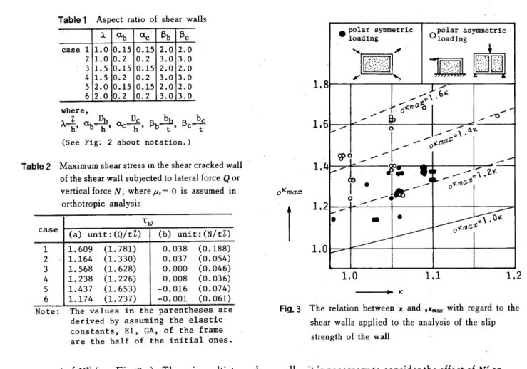
(b)
(T.lrmo)=(ox...lx)
takes
the
value
between
1.1
and1,3
in
suchcase
as shear walls are subjectedto
the
polar
symmetricforces
(see
Fig.
3),
sincea,
for
shear walls subjectedto
the
vertical
force
N
(see
Fig.
2
b)
is
negligible
(see
Table
2),
Table
2
alsoshows
the
maximum shear stressT.
for
shear walls whoseaspect
ratios
are showh
in
Table
1
and which are subjectedto
the
forces
shownin
Figs.
2
a and2
b.
It
is
obviousthat
r.due
to
N
shownin
Fig.
2
b
is
negligible,But,
T.is
affectedby
the
verticalforces,
IV',
acting onthe
edgebeams
asg,tr-:・2trat,S
r'
' hL.[g]z=
m,=..,.fglbSb
rL
V-d(a),lateral
foree
Q
Fig.2
The
externalI,lD,b
Il.,
!i!
t,L Jt
r
7Ii
・"ipt';FFFFFR-FIU;i!i'YtV'
''''''
'''''''
'''
'''
rE
2lt
!s'i!N
ttttttt/
t
tt
't
tt.tt/tt.'
'ttLifFu2t"-,,J{b)
yerticatforce
AT
(c)
verticalfoEce
N'
forces
andthe
definitions
ef sltear walls-143-Architectural Institute of Japan
NII-Electronic Library Service
ArchitecturalInstitute ofJapanTable2
Table
1
Aspect
ratio of shear wallsxabac'BbBc
ease11.0O.ISO.152.02.02LOO.2e.23.03.0
31.5O.15O.IS2.02.0
41.5O.2O.23.03.0
52.0O.ISe.ls2,O2.0
62.0O.2e.23.03.0
where,x=k,%=I}i,
qe-DhC,Bb=!l]i,
Be-btC
(See
Ftg;
2
about notatien.)Maximum
shear stressin
the
shear cracked wall of the shear wall subjectedto
lateral
force
Q
or verticalfo[ceN, where"i
=
O
is
assumedin
orthotrepic analysisTw case(a)untt:(qltz)(b)unit:(NftZ)11.609(!.781)o.038(o.188)
21.164(1.33e)o.037(O.054)
31.568(1.62B)o.,ooo(o.046)
4L238(1.226)o.O08(o.036)
sL437(1.653)-o.O16(o.074)
6L174(1.237)-o.OOI(o.061)
oKmaxT
1,8
1,6
L4
1,2
i.o
e::::IngYmmetriex
O::::In:S)'Trmetr
±c N1/17i・t:.;.././,;i'i/'/'t'11'i'';' r,/.:t,',.1.,.;/g/tt/ttt//t/ttt
.t.illll.il/i,ll,1
N
.'-f..ae.
ge,
x-'el・6" -.v/-Me
.・o
--'---o-'-4S xsl'gptapt -coEo' e' - -x-e ---..1. 'spta:o'7g ".e.
tptapt.o.1.0s1,O
'
1,1
L2
- K'
Note:
The
valuesin
theparentheses
areFig.3
The
Telationbetween
z and ,x.., with regard to thederived
by
assuming the elaStie shear walls appliedto
the
analysis ofthe
slipconstants,
EI,
GA,
ofthe
frame
.
are
the
half
of thainitial
ones. strength of the walltt
a
part
ofNS)
(see
Fig.'2
c).Then,
in
multistory
shear
walls,i't
is
necessaryto
considerthe
effect ofN'
on T..<c)
The
shapefactor
,z...for
shear walls subjectedto
thg
polaT
asymmetricforces
(see
Fig:3)
tends
to
be
larger
than
that
for
the
case(b)
due
to
the
shear
stress
concentration
in
the
wall.But
it
is
expectedthat
the
shapefactor
.x...for
these
shear wallsls
nearlyequal
to
that
for
the
case(b),
because
the
lateral
shear capacity ofshear
wallsdoes
notdegrade
imrnediately
due
to
the
relief ofthe
shear stress concent[ationin
the
wall afterthe
occurrence of
the
slipfailure
oftheir
wall,'
3.
Slip
Strength
ot
The
Wall
of
Shear
Walls
The
slip
failure
ofthe
wallis
the
crushingfailure
causedby
diagdnal
compressiondue
to
shear.Therefore,
it
is
assumed
that
the
slip strength ofthe
wall T.in.,is
the
sum
of
the
pure
shear strengthft
ofthe
wallin
the
stafethat
a
normal stressdoes
not act enthe
slipfailure
plane
and
the
increment
of shear strength Th=uakdue
to
compressiye'
t
t
stress aR
on
the
slipfailure
plane
ofthe
wal19).-
,Twtws=h+th=th+#aitH''"'"''-''"''"'''''''''"''H'''H''"'''-'''''"''-''''''''-・"-''--・-・--・・・・・::;-・・-・・-・-・-・・・(1)
whereIn
the
caseof
the
horizontal
slipping:・
'
th=f(F.,p.)''''H''''--''''''-''"'"''''''''`''''"''''''''""''-'''"''"''"'''''"'''''''''-'''H''"H'''H''''''''''''''<2a)
In
the
case ofthe
vertieal slipping:k=f(L,p.)・---・---・----・---・---・---・----・---・---(2b)
p.,
ph=shear
reinforcement ratio of vertical reinforcingbars
ahd
that
ofhorizontal
reinforcingbars
in
the
wall'
'
'
E,;compressive
strength of concretell;factor
for
the
effectof
the
compressive stress onthe
slip strengthof
the
wallFor
the
casein
whichN'=O,
from
the
equilibrium ofthe
forces
acting onthe
triangular
elgment
ofthe
cempressivebrace
between
the
shear cracks acrossthe
slip
failure
plane
(see
Fig.
4.
In
the
ultimate state,r=
r.ot..], .a.;.ooo and rah=ra),o.),
the
compressive stress aR acting onthe
slipfailure
plane
is
obtained asfoliows.
In
the
case ofthe
horizontal
slipping:
aR==Tuo[uatane-pvTavo,.,.,,-・・・・・・・・・・・・・・--・・・・,.H,.-・・・・・・・・・・・・・・・---・・-・・・・・・,・.,・H,,,,,,.,.,-・・・--・・・・・-・・・・-(3a)
In
the
case
ofthe
vertical slipping:Architectural Institute of Japan
ArchitecturalInstitute ofJapanaR=
korus)
COte-ph
raho-・-"・-・・-・・・・・・・・・・・・{3b)
whererakrd,raho=tensile stress of vertical reinforcing
bars
andthat
of
horizontal
reinforcingbars
whichcross
the
shear
cracks
closeby
the
slipfailure
plane
for
the
casein
whichN'=O
The
slip strengthof
the
wall assumedto
be
IV'=O,
Tuotwsh canbe
obtainedas
follows,
by
substitutingEqs.
(3a)
and
<3b)
in
Eq.(1).
In
the
case
ofthe
horizontal
slipping:th-mpvravo
TltOcwsi==
1-ptane
M''''H''-''-'''""''''H'{4a)
In
the
case
ofthe
vertical slipping: thLmphrahoTuocws,=
1""cote
''''''H''''-"'''-'-''"'''(4b)
kor..,
is
given
approximatelyby
Eq.(s)
by
the
(1)
The
thickness
of
the
wall of shear walls whose%
Fig.4
Forces
acting onthe
triangular
eleTnent(as
shewnby
the
hatched
area) ofthe
compTessivebrace
between
the
shearcracks
(the
directions
taken aspositive
are asindicated)
following
reasonsshear
failure
is:lnducedbytheslip
failureof
theirwall
is
Table3Shear
walls appliedto
the
muitiple regressionanalysis oftheslipstTength ofthewallTtte[urstzhDdbc
tN
e
e)"?tuoCwt)Qduo(ws)HEFE-RENCESPECIMEN(em)<cm)(cm}{cm)Dt}{cm)bb(cm)(cm)Ps<:)ay(IkEg,)em
Fc(-k)em(tDn)degTees)rtz{:cllfi[km)tz(-ck.)
IAO-140.52S.54.S4.S4.53.0e.6o-18Se401.0633.33Z6
O-(1)40.S28.54.S4.S4.S3.0O.6o-ISSe4S1.0631.432.6
o-(2)
40.528.S4.54.S4.S3.0O.6o.185o401.0633.332.6
A-140.528.54.54.54.S3.0e.6O.272930185o451.0640.741.8
A-2
40.S2S.54.54.S4.S3.0O.6O,27293018Se451.0638.94L8
B-1
40.S28,54.54.54.53.0e.6O,53293018Se451.06so.oSO,7
2AO-140.S28.S4.54.S4.53.0e.6o-300e401.0648.24L6
3A7.1.SW-lS2.037.07.e4.57.04.51.SO.67270Sl96o451.0950.3S6.4
7-1.5W-2S2.037.07.04.S7,O4.S1.5O.67270S209o4s1.0950.S57.S
9-1.5W-lS2.037.e9.04.S9.04.S1.5O.672705195e4S1.03SB.956.]9-1.5U-2S2.037.e9.04.S9.04.S1.SO,672705223e4S1.035S.9S8.6
7-.2W-l
67.037,O7.04.S7.04.5LSO.672705198e35k1.104S.OS6.6
7-2W-2
67.037.07.04.S7,O4,SLSO,6727es166e35k1.1047.253.7
9-2W-1
67,O37.09.04.S9.04,SL5O.6727es196e35k1.0650.SSS.4
4A20X20-680.0145.e20.020.04S.O30,O6.0O.792710200oasO.9867.16e,8 ISx18-682.014S.O18.018.04S.O30,O6.0O,603490237o451.02S8.557.3SA1.es-Rw-1S2.037.07.04.57.04,SLSLOS214S327o451.e9Sl,979.1
1.05-RW-2S2.037.07,O4.57.04,SL51.05214S327o401.0979.e19.1
da1.0-RW-137.e37,O7,O4.57,O4.5LSO..702334251o451.0579.061,8
1.S-RW-1S21037.07,O4.S7.04.5L5O.7023342Slo451,0965.86L8 1.5-RW-2S2.037.07.04.57.04.SL5O.7023342Slo4S1,e97LO61.S7A1.05-NR-1S2.037.07.04.S'7.04.5LSLOS227332S1,88?!,0979.979,O
8A1.05-W-167,D37.07.04.S7.04.5L5L0520!2274o451,1064.S7S.4
1.05-W-267.037,e7,O4.S7.0a.sL51.052012274o40I.1068.875.4
3BB-2-.1
13S.Oloo,e20.020.020.017.06.0O.7S4190242o?1,OO63.062.8
B.2-213S.O100.020.020.02e.o17.06.0O.7S41902SOo
?1.0066.463.t,
4Bwc-s
240.0IS2.032.032.032.032.08.DO.S6360o201o401.0649.SS3.1 WC-8A240.0152.032.032.032.032.08.0O.56]600264o401.0654.7S8.0
SBWl-3
ll2.089.012.0IO.O14,O10.03.eO.26SS2021910,O4St1.18a6,944,46BW-2
180.0120.020.020.020,O20.07.SO.7523oe183o4S1,0957.458,O
7B3psO.71A-76120.080.014.014.014.014.03.0O.71165031818,4451.QO67.866.9
8BS-30--S100.0110.0IS.Ol5.020.0IS.O4.2O.6021Sl19423,7so1,0566.453.8 R-30-S 100.0110.0IS.D15.020.015.04.6O.552i8124523,7soLOS60.756.3 R-30-IOloe.o110.0IS.OIS.O20.015.04.6O.S5218126323.750LOS60,7S7.69BW6
100.06S.OIS.OIS.O15.0le.os.eL134166292IS.O?O.9992,479.4
W8
loe.o65.0IS.OIS.OIS.O10.0s.o1.134166191le.o40O.99.S2,O7L6
W9loe.o6S.OIS.OIS.OIS.O10.0s.e1.13al66263IS.O?O,99S3.27L]
10B4S2SW40-79120.080.014.014.014.0'14.04.eO.2S411022S2ZO4SLOS48.144.S4SSOW40-7S12e.o8e.DIa.o14.014,O14.04.0o.so31SO29534.74SLOS50.658.2
4S67W40.-78120.080.014.014.014.014.04.0O.6731SO31229.4451.esS8.165.2
4S50W20-7812e.o80.0.14.014.a14.014.04.0o.so315D33232,64SLOS57.160.7
4SSOW60-78ne.o80.0l4.014,O14.014.04.0O.5031SO3032S.645L054g,o58.S11BRC.Ol-6ne.o110.020.020.020.02e.o6.0O.46266021440.045LOO6S.2SO.7
Note:Theaf
data
rnarked kdenote
the
angle of shearthe
reference.craekspresumed
bythedescription
Architectural Institute of Japan
NII-Electronic Library Service
ArchitecturalInstitute of Japanusually
thin.
Therefore,
the
anglee
ofthe
shear cracksin'the
wallis
almost equalto
4sO.
(2)
th>smpvraoo, k>srphrahodue
,to
the
item
3>
in
section2,
t
ttt
t
t
'
Tuofws);
1.
-thu
''''''"'''''-'''''
:'''':':':,'''''H''''''''''''''''''''''';':'''-'''1'H'''''''''H''''''''''''''''''''''''''''(
5
}
The
multiple regression analysisof
q,or..,
(
= x(,.Q.of..,1
t'l}
by
using assumption4)
in
section2,
ixihere
..Q.o[..)is
the
experimental
lateral
shear capacitydominated
by
the
slipfaililre}
is
m'ade
with regardto
the
43
shear walls(shear
reinforcement
ratioin
the
wallD.=p.=p,)
assumedto
be
IV'=O
(see
Table
3)
to
determine
whatfact6rs
affect T.,,..,given
by
Eq.
(
'5
).
In
this
analysis,
the
combinations ofthe
factors
which areConstant
and'e
orVFT,
andp.==p.=
ph
or(psahr)=(pvayv)=(phayh)
are considered, where a,= a..=oph
is
ayield
strengthof
verticAlhhd
horizontal
wallreinforcernents,
・・
-'
'
'
t/
'
SheaT
walls subjectedto
the
compressive
load
in
the
diagonal
directien
are not applied-tothe
multiple r.egressionanalysis
because
ofthe
fact,
as observedin
the
experiments conductedby
Dr,
Yamad,a3),
thaf
the
lateral
shearforce
appliedto
the
shear walltends
to
increase
after
the
occurrence ofthe
slipping.The
externalforces
ofthe
shear wall subjectedto
the
compressiveload
in
the
diagonal
direction'
,can'be
decomposed
into
two
tYpes
offundamental
components,
Type
I
andll,
as shownin
Fig,5,
The
component eftheType
ll
i.s
thg
va;iable axial co.mpressiveforce
ofthe
boundary
frame.
Therefore,,
the
tendenc\
observedin
the
experimentsis
understoodby
the
reasonthat
even
if
the
lateral
shearforce
ofthe
wall
decreases
in
accordance withthe
occurrence ofthe
slippingthe
shear
strengthof
the
boundary
frame
increases
by
the
variable axial compressiveforce
and consequentlythe
boundary
frame
can
supplythe
lateral
shearforce
larggr
than
the
logs
of one'oithe
wall..'
The
empirical
expression・for
the
slip strength ofthe
wallEq,(6)
is
obtainedffom
the
multipleregression
analysis.The
standard
qeviation
of ..Q.oTus,IQ.of..) calculated accordingto
this
eguation,is smallest among othereqttations
expressed
ip
otherfactors,
'
'
p p p
e
・
,
X`.
xl
i-
'
'・
= Typel+
x.e. -:
;N
,
i
Fig.5,The'fundamental
components ofthe
E\ternal
force
ef a shear wall subjected to the comprefisive'
load
in
the
diagonal
direction
N2
2/t-tt..t/t'''',TyP9II.tttt.
.tt.t''
-P
P "E6oeytut
-te-:F
L3e
1
- 24 shesr valls sllb]ected tD pelar syrmetr ±c loads
other tha" the cempresstve lead tn the direatton of
the diagonel ltne
O 19 shear valls subjected te pelar asyuumEt[ ±c leads x6 shear wslls
(Ps,1.2Z}
net applied te theple regression anelYets
U6
shear walls(Psopl,2Z)
not applted te themult ±ple regressten analysis Xmax=,Xo, . -o
os
e
e o:o .. nxxS eO Axe cTuocm-=2
nn ll'
.56/-ii-
:x:'Shape facter for the shear stress at
the cemter of thewall obtained by
tsetreptc analysis
2,56M
erNo{ pts)=
2.
s6Vil-
+3590
Psextuo(ths)
o
loo
,
2eo
3oo
4eo
soo
-
R(kg!cm2)
Fig.6
'
The
relationbetwelen
.t..ua andF.
obtainedflom
thernultiPle
fegression
analysis oflthe slip strength of43
shear walls
(the
ratioof vertical andhorizontal
wallreinforc'emeni
p.=p.;ph51.2
%),
where cTuo,ouis
the concrete componeatof T.... and
Fl
is
compressivestrength of cencrete
146-r,gxLt-;si
k
1
e24'shearwallssubjectedtopelarsymmetric'loads oLherthanthecemptessiveloadtnthedilectSonof thedtagone1line O19x6shEarshearwallsvallssubje.cted'(Ps)1.2:}topelarnotappl
±editoasymmetrtetheloadsmult ± -'pleregressienanalystsrr6sheaTvalls(Ps{D}'1,2T.)notappliedtethe
multtpleregresstenanalysts80
'
'
'&/'
'60'
Inln,1n/ xtlB/-:rruDcros)=43
'
v40
l--'
l :''
.d]',e1.
tt
o 1'
q.1kmax=X1,
'
'
20
-hs`b"x:Shape 1,atthefacterferthecenterefthewallsheaTstressobtaiued tl,Asv 11by1 tsotroptcanalysis
3590p,
-". 1rTHeCas1=12.56F.+3590Pse:Tuefws]
1'
o
LOl.22.O
3.o
4.
Fig.7
43
e
-
Psi(%>
The
relationbetween
.;... andp.
6btained
frorn
the
multiple regression analysis of the slip strength of43
shea[ walls
(the
.
ratio6f
vertical an'dhorizontat
wall reinfofcementp.=p.=ph\1.2
%},
whFre rTuo[urr,iS
Architectural Institute of Japan
ArchitecturalInstitute of JapanTable4
Shear
Walls
withthe
wall reinforcement ratiolarger
than1.2
%
REFE-RENCESPECIMENz(cm)h(cm)Dc(cm)bc(cm)Di)(cm)bb(cm)t(cm)Ps(Z)Oy(-lsg,)emFe(-!!E,)emN(ton)e(degrees)rcexQ/uoms)t("k,) /Qt,otu"1/T(gek,)・
IB
s5LO51.e6.0'6.06.04.01.03.662900325o
451.1392.184.I
9Sl.O51.06.06,O6.04.e2.01.S329003SOo
401.2662.88S.2
/
1051.051.06.06.06.04.02.01.832900307o
?1.2674.582.9
115!.O・SLO6.06.06.04.02.01.832900356o?1.2662.886.1
2B3651.05LO6.06.06.0'4.0LO1.833000467o
?1・.1385.392.7
3951.051.06.06.06.04.01.01.83'3000・443o
?IL1387.791.3
37'51.05LO6.Q6.06.04,Ol.O1.83rk3000472o
?1.13110.4114.4
'
3851.05LO6.06.06.04.0LO1.83de3000478o?1.13114.1114.7.
405LO51.06.06.06.04.0LO1.83k3000465e
?1.13116.1114.e
4151.051.06.06.06.04.02.01.83*3000446o
?1.2681.9112.9
4351.051.06.06.e6.04.02.01.83-3000448e
?1.2676.5113.0
455LO51.06.06.0'6.04;O2.01.83de3DOO469e
?1.2679.9114.2
Notes:
1)
Thedata
rnarked t denote thediagonal
wall reinforcement,,
2)
When
thediall
reinfercement is vert ±cal anclhorizontal
wall retnforeernents,Quo(ws)
iscalculated
by
substitutingfor
Ps
=1.2Z
tnto
Eq.
(8).
'
Tue[wsi=2.56Viill,+3590ps
,
(kglcmi)
・:・-・・・・・・・・・・・・・・・・・・・・・・・・・t・・・・・・・・・・・・・・・・・・・・・・・"・・-・・・・・・・・・・・・・・・・・・・・・・・・・-・(6}
where
p.=O.O12
whenp.>O.O12
The'restilts
ofthis
regreSsion analysis showthat
factor
{pi
o.)=(p.a,b)=(p.a,.} scarcely affectsthe
slip strength Tuor..F.This'fact
'coincides
witli
the
assumption3)
in
section2,
"The
contribution ofthe
boundary
frame
to
the
sheai stJengthis'
consideredin
Eq.
(
6
),
becquse
the
ultimate sheart/
stress, T.o[.., onthe
failure
plane
is
determined
by
usingthe
shapefactor,
x, otthe
shear stressof
the
wall whichdepends.Qn
the
geometrical
condition
of a walland
aboundary
fra;ne.
,
,.
The
results ofthis
regression analysis are shownin
F.igs.
6
and7.
In
the
case
of
the
shear
walls with vertical andhorizontal
wall reinforcements whose ratiois
larger
than
1.
2
%,
it
is
pessible
to
estimate adequatelythe
slip strength ofthe
wallby
substitutingpb=O.
O12
in
Eq.
(-6
)
(see
Table
4
andFig.
7),
But
it
is
obtainedfrom
the
experimental resultsthat
the
contributioR ofthe
diagonal
wall・ reinforcementto
the
slip strength ofthe
wallis
proportional
whenpsuSl.8%
(see
Table4
andFig.7).
4.
Lateral
Shear
Capacity
ot
Shear
Walls・
,
,
,'
The
lateral
shear capacitydominated
by
the
slip
failure
with regardto
shear walls assumedto
be
N'=O,
Q.or..),
is
given
by
Eq.{7).-
'
Quodws)=ii/uoiws)tt=
Tx":{:S)tl=
TiC:/us)tl''''''':'-'''''''''''''''''''''''''''i''''''''''''''''''''.',,.,,.,,,.,・,・-・・・-・・・・・:[.(7)
'
tt
The
frequgncy
distribution
ofthe
ratio ofthe
experimental value ..Q.b,..,to
the
calculated valueQ.,,..)
obtainedby
substituting
Eq.
(
6
)
in
Eq,
(
7
),
..Q.oc..)fQ.o,.., with.regardto
the
43
shear wqllsapplied
to
t.he
multiple regression analysis of T.oc..],is
shownin
Fig.8.
It
is
seenfrom
Fig.8
that
this
distribution
is
nearly normaldistribution.
The
mean
and,the
standarddbviation
ofthese
ratios are1.002
and
10.4
%,
respectively.The
corretation coefficientof
i.,,..,
is
O,
907.
It
is
seenfrom
Fig.
9
that
most
of
the
shapefactor
xfor
shear wallsfailing
in
s]ip shearis
almost1.
o5.
Therefore,
the
practical
expression,
Eq.(8),
ofthe
lateral
shear capacityis
giveh
by
substituting z=1:05in
Eq,(7),
The
mean
and
the
standaTddeviation
of ..Q.,f..,IQ.o..,and
the
corTelationcoefficient
of7.,,..]
calculated accordingto
Eq.(8)
(see
Fig.Il)
are similarte・those
accordingto
Eq.(7)
(see
Fig,8).
Quocws,=iuortus,tl=(2・4VjiT+3400p.)tl
(kg)''''''-''''vt・・・・・・・・・・・-・・・・-・・・-・・・・・・-・・・・・・・・・・・-・・・・-・・-・・-・・・・・・・(s)
where
E,=compressive
strengthof
concrete(kg/cm2)
p.=shear
reinforcement ratioin
the
wall, wherep.==O.O12
wherip.>O.O12
The
retationbetween
the
verticalload,
N,
appliedto
the
shear wall and ..Q.o,..,is
shownin
Fig.
10.
It
is
seenfrom
Fig,
lo
that
the
verticalloads,
N,
scarcely affectsthe
experiFientallateral
shear capacity ..Q.o,..).This.
fact
coincides withthe
assumptiop4)
in
section2.
When
the
lower
bound
oflateral
shear capacitydominated
by
the
slipfailure,
Q.e,...i.
andthe
upperbound
of one-147-Architectural Institute of Japan
NII-Electronic Library Service
ArchitecturalInstitute of Japan ptu[-]avLL1lg:Y
1210s642o246810
c:Qttdrm;//Qso(m)
rema:=O.7
O,8
O,9
LO
1,1x12L
Mm
.
3
Results o'E theeretical
expression
fisheer.wails CPs(DPI.2X) 6 shear'walls CPs>1.2:) 43 sheai walls (Ps!1,.:X) exQuocws) meEn 1.oo2 standard deviatien
Qvv(pt]
,,
o.zoaPs
==PA
=Pv
Results of pF'actical expressien 43 shesr wails (Pssl.2X) t:Que(ws) mdart''
'o',
Qmocwilj
O,7
O.8
O,9
1,O
LI
1.2
1,3
eiQ#ettus}
Qvocza)xmax=1,os
Fig.8
Frequency
distribution
ofthe
ratiovalue ..Q.e[us) te the theoretical
to
the
shear walls whoselateral
dominated
by
the
slipfailure
oft
t
tt
tt
t
ttt
Quofvs]ma=
aregiven
by
Eqs.
g
a,b
andbound
(see
Fig.11).
sta"datd 99SdevtEtten O.112 L
n
-n
"E-es.
"egdi',-T
/t1,31,21.0O.8
o.
e24 shear walls subjected to polar symetrZc
,leads
other than the eompressive legd ln thedtrectton of the diagonsl line
O19, shear walls subjected Lo'polar asym:etric
loads
・
'
'
X6 shear walls,
(Ps)1.2X)
"ot applted te themulttple regresston a"alysts
n6
ehear walls(Ps(D}>1.2Z)
not applled tothe mult ±ple regTesstbn ahalysts
sL.
---J","'-x-r
,----r--'-/x
s."
of
the
experimental valueQ.or..,
with regardshear capacity
is
,
ttt
'
the wall10
a,b,,
onedatum
/
Fig.9
95
1,O
ms
1.1
1:2・
1,3
ttt
'
-x
'
The
ratio ofthe
expFrimental vaue evQ.,,..ito
the
theoietical
valueQLGf..]
andthe
shapefactor
for
the shearstress atthecenter
of'the wall, Tlan, obtainedby
the
elasticap.
,alysis
with regaT,dto
55
shear walls, whose shearfailure
is
induced
by
the
slipfailure
ofthe
wallis
below
the
lower
bound
andfour
data
are'abovethe
upperi
when
Q.,c.enltl$60kglcm2
・
.
・,・
-
,・.,
,・
,
Quocuamin=O・8Quo(wsi''''-"''"'''''''''''''"''-H''"''':'''''''''''''"'''''''"''''''r'''''"'''s'v.:""t-''-''"''-,(9a)
Quocwsttacr=1,2Quoiws)''-'"''"'''-'''''-'--'''"`'"'''t`''''"''''''/H''"i''"''"''''''J''H''''''H'''H'-H'-H'':'(10a)
when
Quocwetltl>6okglcmt
,
Quocwennttn=Quo{ws,-12
tl
(kg)''''''"'''''''''''''-'''''''"''-''""-'''-''-''''"''"''"r'"'''"''''''''''''''(9b>
Quocwsmax=Quocwsi+12
tl
(kg)
'"':"'L"'"''''''"'''"''"''H''"''"'''"''"'k'Lk''''''"''H'''''"-'H-'''''(10b>
After
the
regressionanalysis,
manyone-bay one-storyshear
walls,(shear reinforcement ratiop.Ei
p.==
ph)
assumed・
to
be,
N'=O
are coll.ected(see
Table
5),
With
regardto
the
shear wallsfailing
in
slip sheaithe
relationbetween
the
'
experimental
valuesand
the
values calculated accordingto
Eq.
(
s
)
is
shownln
Fig.
n.
Most
ofdata
are
plotted
in
the
zone
between
the
lower'bound
Eq.
(
9'
)
and
the
upperbound
Eq.'(10).
The
'rnean
and standarddeviation'of
the
ratios of ..Q.ot.,,IQ.o',ua
with
regardto
tetal
shear walls are'1.os3 and14.7%;
resp6ctively,'The
c6trelatibnShearwalls(N=O)..Loadin N=O .N)O
mean
O.989
stanarO.093deviation
polarsyrrcrnetricleadtng othertha"the"compressive loadinsalongad ±agonal 1±ne'
÷
.i23shearwallse1shEarwall'
/'
'/ttt
t
t
'
'
freq'ueney2,4,6polarasymmetr ±eloadtng,5shearwallsO14shearwalls'
total'28shearwallsISshearwallst/'
//e
----
'---ttt
---
'-o-o-=ssorH t...'ee'ttee/o-o--m-n'
L2---?gx.-o
'tt'-o'-.--o
l.2g's'・1.0cr-.0,8O,7
ltuL.・el
oo el="Lgdiw08---rol
oo---o---'---
---T
t-.-"'
7
--'
OO.2O.4O,6O.81,O1,21.4
oo.o2o.o4.o.o6o.o's.o,,leo.12o,14
Fig.10
'
-M"
Q..N(..)・
・.
N
,
,
(2beDc+tl')R
.,
'
The
relalionbetween
the ratio ofthe experirnental value ..Q.ty.., tothe theoretical valueQ.,,..,
and th'everticalload
N
with'
regard
to
the
shear wall whose shearfaiiure
is
induced
by
the
slipfailure
ofthe'wall
(the
ratioofvertical andhorizontal
wall'
reinforcement'p.=pv=phSl.2'%)
'
''
'
Architectural Institute of Japan
ArchitecturalInstitute of Japancoefficient of
i.,c.st
is
O.856.
.
,
5.
Conclusions
The
following
conclusions with regarclto
one-bay one-story shear walls maybe
drawn
from
this
investigation.
(1)
The
slip
strength
of
the
wall
is
affecFed
by
the
square
root ofthe
compressive strength of concrete andthe
ratio of wall reinforcement.
In
the
case of vertical andhorizontal
reinforcements,however,
whenp.ll,2
%
the
contribution of wall reinforcementto
the
slip strengthis
notproportional
but
becomes
constant
whilein
the
case of
diagonal
reinforcement,it
is
piopbrtional
whenp..$1,8
%.
(
2
)
'
The
lateral
shear capacity of shear wallsfailing
in
slip shear ofthe
wallcan
be
estimated
adequately
(mean
=O.
998
(1,
053>,
standarddeviation=O,
112
(O,
147),
correlation coefficient=O.883
(O,
856),
the
sized values
denote
ones with regardto
total
shear walls)by
the
practical
expression
Eq.<s
),
Table5
Shear
walls
gollected
afterthe
regression analysl's REFE-RENCESPECI"[EN z{ctu)'h(em)De(etu)be(cm)ng(em)bb(cm)t(am)?s(z)"(::2)Fc(2fi,)N(ton)G(degrees)
'exque(vs>
.(thkm2)
que(vs)Tt(thk.2)
9AleRw
S2.o37.0zo4.S7.04.s1.ee.7e2330400o40
7.071.B
leAO.35-FTI-1 73.eS2.010.06.S10,O6.s2.0O.3S1710e4eo?66.1S6.2
O,3S-FW-2
73.o52.010.0・6.S10.06.sz.oO.3S1710340o?6S.3S6.2
O.70-VW-1
73.o52.010.06.S10.06.s2.0e.7o19SO362e?
7s.e69.5O,70-FW-2
73.oS2.010.06.510.06.s2,OO.7019SO362oT 64.269.S1.0S-FW-1
73.oS2.0lo.e6.S10.06.s2.01.0SI9SO362o?
79.2Sl.4・1.0S-FW-2
73.oS2.010.06.S10.06.52.01.0Szgse362o!Bl.SSl.4
11A2eW-O.6F-173.o52.010.06.S10.06.s2.0O.3S2217329o1
66.4SS.4
20W-O.6F-2 73.oS2.010.06.S10.06.s2.0O.3S2217329o?6S.S5S.4
20W-1,2F-1 73.o52;Ole,o6.510,O6.s2.eO.3S2217]29o?77.3jS.4
20W-i.2F-2 73.oS2.010.06J10.0・6.s2.0O.3S2217329o44 eo.15S.4
3SW-1.2F 73.eS2.D10.06.510.06.53.SO.3S2241214o?
44.247.0
12A.O.3S-SW-7.0 7S.oS2.0lo.e7.010.0Lo2.0O.3S19U340o? S8.3S6.2 O.3S-SW-S.S73.oS2.0lo.eB.S10.08,52.0O.3S1911359o!
75.3S7.4O.3S-SW-10.0
73.o52,O10.010.010.010.o2.0O.351911330o? 6S.Sss.so.7o-sw-7.e
73.oS2.0lo.aze10.07.o2.0o.7e1911345o?
63.968.4
O.70-SN-8,S 73.oS2,O10.08.510.0s.s2.0O.701911352o?74.868.8
O.70-SW-10.0
73.oS2.010.010.010.010,o2.0O.701911345o?7S.968.4
10SO.64-S.G/1.7-O(1)22.448.0s.sS.620.0IS,o1.7O.772290285e4579.36G.7
SO.64-S.61.7-O222.448.0S.65.620.0IS.L7Oa772290267o4 84.86S.4 12BBl-1 ISO.3102.9le.1660.96IS.24IS2.410.I6o.sS30029So3871.0S8.2
B2-1
18e.3102.910.1660.96IS.24152.410,16o.s536e167o42S3.94S.o
]3-2180.3102.910,1660.96IS.24IS2`410.16o.s5400276o3S
62.e・S6.9 B7-5ISO.35S.2S10.166n,96IS.24152.410.16o.s5260262o40
63.7SS.9B8-5
18e.319S.110L1660.96IS.24IS2.410,16e.s522e'239o4549.SS4.1
13BIFI-O-O-Ol 7S.O120.0IS.O2S,O20.025.08.01.4110724824.Se・tt91.77S,6 M-I-O-O-02, 7S.O120.0IS.O2S.O20.02s.e8.01.4110724824.64288.378.6
M-m-o-e-ol 75.0120,OIS.O2S.O20.0Z5.08.0O.731072Sl24.64168.364.0
M-II!-O-O.e2
7S.O120.0IS.O2S.O20,O25.b8.0O,7310728124.6S3
lo.o64.014B4S2SW40-T8 12e.o80iO14,O14.014.014.04.0O,2S31SO]7429,351 65.654.9
ISBAW-1
9067,S10.010.017.5IO.O4,OO.6S582et2808.04S 73.962.3 16BB 2S9.817S.450,OS6.0,so.o41.011.SO.373670292e3S66.0・S3.6
17Bw-e
lse.o100.020.02o.e20.020,O7.0O.9114242S912.0!
・69.069.6
ISBNe,1 220.0130.040.040.04o.e40.018.0O.4236302S2o3577.0S2.4
lgBmoNO 2!S.O14S,O2S.O25.030.025.010.0O.64404027537.S?56.461.S
B-' 13S.Oo.o15.015.020.0IS.O4.0O.30329027013.S45 62.649,6 WO-1.0135,O80.0!s.eIS.O20,Ols.e4.0LO722027013.S4S
7B.473.4
WO-I.OT 13S.Oso.eIS.O15.020.015.04.0LO722027013.545 82.173.421BNo.27
2!O,O116,O20,O20.026.012.04.0O.53410627S!8.044
50.SS8.D No.28 220.0116.020.020.026.012.0s,oO.42410627828.04339.S54.3
Ne.29 220.0116.020.020.026.e12.0G.Oe.36410627S2S.O47 32.3・S2.3No.30
220.0116.020.020.026.0!2.0LOO,30410627828.04S
35.7SO.2221Wll
80.04B.O12.012.011.09.D4.0O.2S1900146o・41 4S.317.S W14so.o48.012.e12.012,O9,O4.0O,6]9SO146o40
se.649.4
WIS eo.o48.012.012.012.09.0103950146o41
51,963.e
23BLIFO
lse.o100.020.020.020.020.07.0O913SOO13S12.0!
48.1SS.8
24BHS-Ol130.0120.0IS.O6S,O3o.e65.0IS.Ooi'e3S2S2SOo?
71.16S,2
HS-04 1]e.o120.0IS.O6S.O30.06S.OIS.OO.8352S2SOo45 73.06S.1 Hs-es 130.0120.0IS.O6S.O30.06S.O15.0o.s3S2825eo?64,763.8
HS-06 130.0120.0'IS.O6s.e3o,e6s.e15.0e.g3S2S2SOo? 64.063.S HS-07130.0z2o.oIS.O6S.Oso.e6S.Ols.eI.63528233o?
S4.977.4
HS-08
130.0120.0I5,O6S.O]o.o65.0IS.OL63S28233o?8S.677.4
HM-Ol2SO.O22o,e30.012S,O4e.o12S.O30.0O.8398126So4S
G6,666.1
HM-02 2SO.O220,O30.0125.040.012S.O30.0o.s3981265o45 66.76S.3 2SBSR125BE02Sle120,Olse.o15.e15.020.0IS.O3.0O.414200370o?62.S.60.8
sRlooBEo2sle12o.e120.015,OIS.O20.0IS.O3.0O.434200370o?
6S.960.9sRo7sBEe2ss IZO.D90.0ls.eIS,O20.0IS,O3.0O.S74200305o?
8a.371.5
SR075BE02SIO120.090.0IS.OIS,O2a.ols.a3.0O.4]4200370o?
67.S6e.8
251FW-1
200.0ss,e15.0IS.O2o,ele.os.oO,8383123SIS.O45
6e.9.o
FVJ"2 200.0BS.OIS.OIS.O10.0.2S.Os.oo.s.381129718.0? G9.668.6 FW-3 200.085.010.02S.O10.02S.Os.oo.s38312812o.e?66.96],4
27BVIN-1
170.0105.020.02e.ozs,oIS,O6.0O.42408723534.04S 6S.87.42SBIB
110.0122.e10.022.022.a22.03,OLO661S4!9.o4S
S6.183.1
Note:The
mark ftin
the
colurnn ofOY
denotes
omctx.
Architectural Institute of Japan
NII-Electronic Library Service
ArchitecturalInstitute of JapanThe
expansion
of
the
shear
cracked
orthetropic
wallpanel
whichbehaves
asdiagonal
compressionfield
by
shear causes
the
swelling ofthe
boundafY
frame.
But,
in
a multibay or mu'ltistory she'ar'whll,the
s'welling'of'the
intermediate
column or 'interm'ediatebeam'
is
res-trained
by
the
adjacent wall.This
fact
meansthat
the
wall of amultibayor
multistory shear wallis
effectivlely
confined
by
the
boundary
frame:
'
''
Consequently
the
lateral
shear6apacity
of multibay er multistory shear wallsfailing
in
slip shear oftheir
infilled
wallpanel
is
larger
than
the
capacity
galgulated
by
the
expression
pTopo\ed
in
this
paper
with regardto
one-bay one-story'shear
wall assumedto
be
N'=OiO).
Therefore
the・lateral
shear
capacity
of
a
wallframe
structure
.is
underestimatedby
the.
expressionproposeid
in
this
paper
and
consequentl'y'is
safely
estimated,
'
t/
References・・
1)
S.
Sugano:Summaries
ofTechnical
Papers
ofAnnual
Meeting
ofArchitecturaL
Institute
ofJapan
(A.I.J.
),
Oct.
]g73,
pp.]3os-l3od
(in
Japanese),
2)
M,
Hirosawa,
T.
Akiyamaand'
M,
ies
ofTechnical
Papers
ofAnnual
Meeting
of'A,I,J.
,Oct.
Ig75,
pp.1173-1174
(in
Japanese),
'
3}
M.
Yamada:Gihodo
Publishing
Co.
LTD.,
Aug.
1976,
pp.l13-l14
{in
Japanese).
4)
S.
Mochizuki:
Failure
ofWall
Panel-,
Trans.
ofA.I.J.,
No.306,
5)
M,
Tomii
andH.
Columns
oftheir
Boundafy
Frames
Part
1,
2
and3,
pp.75-83,
No.275,
Jan.
1979,
pp.45-53
"n
English)
6)
M,
Tomi.i,
T,
SueokaandH,
Hiraishi
:
45-Degree
Orthotropic
Plates
Part
1
and2.
Trans.
ofA
60
(in
Eng]ish).
'
7)
Ml
TomiiandF,
the
Japan.
Concrete
Institute
(J:C.I.
);
Vol,4,
198Z,
8)
F,
Esaki,
'K.
Funamoto
andM.
9}
Y.
Suenlaga
andR.,
Ishirnaru
:
Kinematic
Analysis
A.J,J.,
No.220,
June
1974',
pp.1-7
(in
Japane'se).
10)
F.
Esaki,
M.
TomiiandM.
of
J.C.L,
VoL6,
1984,
pp.477-484
(in
English).
References
efthe
Shear
Walls
Subjeeted
'to
Polar
IA)
M.
(Part
3),
Trans.
ofA.LJ.,
No.60,
Oct.
1958,
2A)
M,
Tomii
andS.
pp.301-304.
3A)
S.
Mochizuki:
Trans
ofA.LJ.,
Ne.249,
Nev.
1976,
pp.13-23..
4A)
M.
Tomii
ei al.:Reports ef5A')
'
S.
Mochizuki'andS.
6A)
S.
MochizukiandS,
'7A)
S.
Mochizuki
andY.
Hosaka:
--150-120
['100
=
gx.i---e
:=av:
se
6o
40
1
・2o
Fig:,11
On
the
Ultimate.Shear
Strength
ofReinforced
Concrete
Shear
Walls
-Bearing
Strength
Controlled
by
Slip
,Aug.・'1981,
Hiraishi
:
Elastic
Analysis
ofFrarned
Shgar
Walls
by
Considering
Shearing
Deformation
of thelleams
andTrans.
of4.I.J.,
No,273,
Nov.
1978,
pp.25-31,
Ne.274,
Dec.
]978,
t
tt/
Elastic
Analysis
otFramed
Shear
Wal1s
by
Assurping
their
Infilled
Panel
Walls
to
be
.I.J.,
No.280,
Junel979,
pp.1'Ol-109,
No.284,
OcL
1979,
t
/
'
'
'
.//
t
t
'
t
t
Esaki
:
Predicting
Methed
fer
Shear
Failure
Medes
efReinforced
Co'ncrete
Framed
Sheai
WalLs,
Trans'.
ef'
pp.
297'304
"n
English}..
・
Tomii
:
Rep6rts
ofKyusyu-Chapt'er
ofA.
I.
J.
,MArbh
lgs3,'
pp.
221-224
'(in
Japanese).
of
Concrete
Mernbers
undeTg]ombined
Stresses
(Part
,3),
Trans.
DfFulita
:
Studies
onFailure
Mechanism
ofMultibay
orMultistofy
FTamed
Shear
WallF,
TTans.
.Symmetric
Loads
(all
in
Japa"ese):
.
.
Tomii
:
Experimental
Studie,s
onEffect
ofDi4ggnal
Loads
to
Reinforced
Concretgl
Plateg
Having
Frame
atBoundary
pp,389-392,
,
Miyata
:
Outline
ofSlteaT
Tests
Concerning
Puake
Resisting
Walls
Having
Various
Opening
TStudy onShearing
Resistance
ofQuake
Resisting
Walls
Haying
'Various
Openings
No.I,
TranS.
ofA.I.J.
,
No.66.
0ct.
1960,
'
'
t
t
'
t
t
'
Experirnents
onRestri6tion
Effects
by
SuTrounding
Frame'
ofReinforced
Conc[ete
Wa'11s
After
Cracks,
'
CAugeku-Kyushk-Chapter
ofA.LJ.,
.Feb.
1978,
pp.175r182.
Matsuo
:
Summaries
ofTechnical
Papers
ofAnnual
Meeting
efA.
I,
J.
,Sep.
1978,
pp.
1ts37-l638.
Kawabe
:
Summaries
ofTechnical
Papers
ofAnnual
Meeting
ofA.
I.
J.
,Sep.
1979,
pp.
1459-1460.
Summaries
efTeehnical
Papers
ofAnnual
Meeting
ofA.
I.J.
,'
Sep.
1979,
pp.
1473-l474.
O
ZO・
40
60
SO''100
120
'i
Quotto,)
''
-'.
tl
(kg!cmt)
ttt
/t'
The
relationbetween
the
experimenta! rnea" unit sheaT stress, ..Q.qua1tt, on thehorizontal
section ofthe
,shearwallswhose
shearfailure
is
induced
by
the
slip