Research on Highly Active and CO-Tolerant
Pt-Skin/Pt Alloy Hydrogen Anode Catalysts for
Residential Fuel Cells
A doctoral dissertation presented to
Interdisciplinary Graduate School of Medicine and Engineering
University of Yamanashi
September 2017
Guoyu Shi
Contents
Chapter 1 General introduction
1.1 Research background………1
1.2 Polymer electrolyte fuel cells (PEFCs) and current issues………3
1.3 New type CO-tolerant catalysts………7
1.4 Objective and scope of thesis………8
1.5 References………10
Chapter 2 Electrochemical evaluation of hydrogen oxidation reaction
(HOR) activities, CO tolerance and robustness on stabilized Pt-skin/Pt
alloy anode catalysts
2.1 Introduction………172.2 Experimental methodologies………17
2.2.1 Preparation of catalyst working electrode………17
2.2.2 Evaluation of CO-tolerant HOR activity and durability………26
2.3 Results and discussion………27
2.3.1 HOR activity and durability on stabilized Pt-skin/PtCo alloy catalyst without and with the exposure of CO………27
2.3.2 Non-precious alloy metal M effect (M = Fe, Co and Ni)………35
2.3.3 Particle size and core-alloy composition effect………44
2.4 Conclusions………52
2.5 References………52
Chapter 3 Mechanistic studies of HOR and CO tolerance on stabilized
Pt-skin/Pt alloy anode catalysts by DFT calculations and in situ XAS
3.1 Introduction………553.2 Experimental methodologies………56
3.2.1 DFT calculations………56
3.2.2 In situ XAS measurement………59
3.3 Results and discussion………59
3.3.2 In situ XAS study of CO adsorption on stabilized Pt -skin/PtCo alloy
catalyst………64
3.4 Conclusions………68
3.5 References………69
Chapter 4 General conclusions and outlook
4.1 General conclusions………734.2 Outlook………74
4.3 References………75
Research achievements
………781
Chapter 1
General Introduction
1.1 Research Background
Fossil fuels, including coal, oil and natural gas, have been used by humans as dominant energy sources. They are exploited to generate large quantities of heat, which can be converted to electricity by a thermal power plant in a low-cost and reliable way. However, combustion of fossil fuels has caused serious environmental problems due to exhaust emissions during power generation, such as global warming and air pollution. In addition, fossil fuels, though seeming abundant right now, are non-renewable and are being depleted much faster than new ones are being produced by the nature. It is thus highly required for an increase in alternative renewable and clean energy to solve the energy crisis and to protect the environment. Energy sources such as sun, wind, geothermal, hydropower etc. have been regarded as renewable energy that can reduce environmentally harmful emissions. However, it remains challenging to find suitable means for energy storage due to the intermittent nature of the renewable generating options such as solar or wind. Hydrogen has been widely recognized to be a promising energy carrier, since it offers the prospect of large and long-term storage capacities. Hydrogen can be produced from electricity generated from renewable energy sources by the electrochemical splitting of water, i.e., water electrolysis. Hydrogen also can be produced by steam reforming of fossil fuels such as natural gas. Even though the process of the steam reforming of natural gas (mostly CH4)
is endothermic, which decreases the system efficiency, the overall efficiency of the state-of-the-art fuel cells combined with the fuel processing system (reformer-fuel cell system) is still much higher than the case of conventional thermal power plants or internal combustion engines, as stated below.
Fuel cells (FCs) convert chemical energy of fuels and oxygen in air into electricity via the electrochemical reactions with high energy efficiency and minimal emission. When pure hydrogen is used as the fuel, the theoretical energy efficiency of FC is as high as 83% (based on higher heat value (HHV) and assuming no heat recapture) and only liquid water is produced. Practically, the power generation efficiency decreases due to overvoltage losses arising during fuel cell operation. Such a loss is exhausted as a form of heat. For residential co-generation fuel cells (Figure 1-1) with the use of hydrogen-rich gas (reformate) as the fuel, the exhaust heat produced during electrical power generation can be reused as a form of hot water, such that a high operation efficiency of ca. 80% (HHV) has
2 been achieved (e.g., Osaka Gas’s residential FCs).
FCs are typically classified into five types by electrolytes and operating temperatures they employ, such as alkaline fuel cells (AFCs), phosphoric acid fuel cells (PAFCs), molten carbonate fuel cells (MCFCs), solid oxide fuel cells (SOFCs), and polymer electrolyte fuel cells (PEFCs).
Figure 1-1 Schematic diagram of a residential fuel cell cogeneration system. City gas
Fuel Processor
Fuel cell stack
Hot water tank Light Bath Kitchen TV Air conditioner Heating Refrigerator Electricity
3
1.2 Polymer Electrolyte Fuel Cells (PEFCs) and Current Issues
Among the different types of fuel cells, PEFCs attract the most attentions and are being actively investigated as power sources for electrical vehicles (FCVs) and residential co-generation systems because they can operate at relatively low temperatures (from ambient temperature to ca. 100 oC) with quick start-up and easy maintenance. Japan has taken the pioneering role in the research and development (R&D) of PEFCs for FCVs and residential use. In 2009, a 1 kW-class residential FC system (Ene·Farm®) was firstly commercialized in Japan, and the total number of systems installed had exceeded 150, 000 at the end of 2015. Mirai, the first commercially available hydrogen powered FCV, was released by Toyota in December 2014. Japan has announced plans to expend the application of stationary fuel cells and fuel cell vehicles for realizing a hydrogen society, especially by taking advantage of the Tokyo Olympic Games in 2020. As examples, the Japanese government aims to be installing 1.4 million “ene-farm” residential fuel cells by 2020 and 5.3 million by 2030. Toyota has set targets to achieve annual global sales of 30,000 hydrogen vehicles by 2020. For such large-scale proliferation of fuel cells, the reduction of the system cost and improvement in durability are quite essential. Thus, it is necessary to carry out research and development to improve performance and durability of fuel cells.
In general, a PEFC consists of a polymer electrolyte membrane (proton exchange membrane) sandwiched between a porous anode and a porous cathode. The construction of a single cell of PEFC is schematically shown in Figure 1-2. Hydrogen and oxygen (or air) are fed to the anode and cathode compartment, respectively, in which the hydrogen oxidation reaction (HOR) at the anode and oxygen reduction reaction (ORR) at the cathode take place to produce an electrical current and H2O. Each electrochemical reaction and the
cell reaction for the PEFC system can be expressed as follows:
Anode : H2 2H+ + 2e (1-1)
Cathode : 1/2O2 + 2H+ + 2e H2O (1-2)
4
Figure 1-2 Schematic of a PEFC.
Anode
Cathode
Gas diffusion layer
Electrolyte
5
At present, to facilitate both the anode HOR and cathode ORR reactions, Pt and/or its alloys have been employed as catalysts, which account for the dominant cost of fuel cell stack. While the ORR kinetic at the Pt cathode is sluggish, the HOR rate on Pt anode catalysts in acidic media is so fast that the potential losses at the anode are negligible even for very low Pt loadings (ca. 0.05 mgPt cm-2) [1-5]. This would hold true for FCVs fueled
with pure hydrogen gas stored in onboard high pressure tanks. For residential fuel cells, the fuels are typically hydrogen-rich gas (reformate) which is produced by the steam-reforming of raw fuels (CH4, C3H8, or kerosene) in a fuel processing system (FPS). After the
reforming, the resulting reformate is sent to the reactors for water-gas shift reaction (WGSR) to bring the CO concentration down to a few percent by volume or less. The hydrogen is purified further by a preferential oxidation (PROX) of CO, which reduces the CO concentration to less than about 10 ppm. It has been recognized that even such small amounts of CO in the reformate can poison a pure Pt catalyst because CO adsorbs strongly on Pt surface, reducing the number of active sites available for H2 adsorption and oxidation
[6,7], as depicted in Figure 1-3.
To mitigate the CO-poisoning or enhance the CO tolerance of the anode catalysts for reformate gas PEFCs, many possible solutions have been proposed. For example, an oxidant bleeding technique has been employed [8-15]. By injecting low levels of an oxidant such as air, oxygen, or hydrogen peroxide into the anode fuel stream, the CO concentration in reformate can be reduced by ways akin to selective oxidation of CO. It was reported that, by using an air-bleed, the CO tolerance of a Pt anode was increased, enabling the CO concentration as high as 100 ppm [8]. However, some negative effects of air-bleed should be noted, e.g. formation of hydrogen peroxide (H2O2, by chemical reaction of O2 with
hydrogen adsorbed at the anode), which degrades the proton-exchange membrane (PEM) [14,15] or gaskets.
In addition, high-temperature operation was shown to be beneficial for improving CO
9 H H O C O C H H
Pt
6
tolerance [16,17], because the CO adsorption coverage on the catalytic sites can be lowered. Increasing in temperature also facilitated oxygen permeability through a membrane to reach the anode where the CO could be oxidatively removed by such permeated O2. In addition,
the activity for the oxygen reduction reaction at the cathode can be enhanced. The key issue in high-temperature operation is to develop alternative PEMs that can be operated at temperatures higher than 100 °C, as well as the electrocatalysts with high durability.
The use of CO-tolerant catalyst is an essential solution. It has been found that addition of element(s) to Pt such as Ru, Sn, Os, Mo, etc., either alloyed or as adatoms, yields appreciable improvement in the CO tolerance compared with pure Pt [18-43]. Their outstanding performance for the electrooxidation of both methanol and H2 containing CO
has been discussed mainly in relation to a bifunctional mechanism and a ligand effect. The bifunctional mechanism, as initially discussed for PtRu alloys, asserted that ruthenium was able to provide oxygen-containing species at more negative potentials than Pt, whichwas responsible for the electro-oxidation of CO adsorbed on adjacent Pt sites [18,25]. The ligand effect indicated that the presence of ruthenium and other metals altered the electronic properties of Pt causing CO to adsorb less strongly on the catalyst surface [26]. It has been suggested that both the bifunctional and the electronic mechanisms may contribute to the enhanced CO tolerance of Pt-alloyed catalysts. At relatively high potentials (e.g., > 0.35 V), the bifunctional mechanism was assumed to be predominant. At relatively lower potentials, e.g., in reformate-PEFCs anodes (< 0.1 V), the ligand effect predominates because CO could not be oxidized (or the oxidation is minimal) on both alloyed and bare Pt catalysts at these potentials [42,43].
It has been reported that the use of metal oxide (MoOx, WOx, SnOx, RuOxHy, etc.) as
support material and/or co-catalyst for Pt or Pt-Ru was also found to contribute to the enhancement in CO tolerance [44-56]. The oxides were expected to play an important role in promoting the electro-oxidation of CO by supplying active oxygen species, i.e., the bifunctional mechanism. A recent FT-IR study showed that MoOX could enhance the CO
tolerance of PtRu by weakening the CO adsorption, according to the ligand effect [47]. Takeguchi et al. also claimed a ligand effect of SnO2 on Pt-Ru: SnO2 was found to decrease
the Pt-CO bond strength, resulting in enhanced CO tolerance on HOR [53]. Recently, in situ X-ray absorption spectroscopy (XAS) experiments clearly evidenced that the interactions between the Pt particles and the carbon with several transition metal oxides (Pt/C-MOX),
including SnO2, promoted changes in the Pt 5d band vacancy, which affect the rate of the
ethanol oxidation reaction (EOR) [55]. Ogihara et al. proposed that the electronic modification of Pt2Ru3 by Sb-doped SnO2 support (denoted as Sb-SnO2) was essential for
7
enhancing CO-tolerant HOR activity by suppressing linear CO adsorption at step/edge sites to maintain the HOR active sites [56]. The electronic effects have also been involved to account for the unique CO-tolerant electrocatalytic activity for hydrogen oxidation on Pt/WOX and Pt/Ti0.7W0.3O2 (the CO electrooxidation onset potential could be lower than 0.1
V vs. RHE) [46,49].
In addition, the structure of the carbon support was shown to influence the CO tolerance of Pt-Ru catalysts [57-62]. Various materials such as carbon nanofibers, carbon gels, carbon nanotubes and graphene, as well as their chemically-modified ones have been investigated as supports for Pt-Ru anode catalysts. The beneficial effect of these new carbon materials has been attributed to the extensive surface area, and the excellent electronic and reactant/electrolyte transfer properties, e.g., the adsorbed CO could be effectively removed in a porous carbon gels due to the high diffusivity [62]. Some studies proved that engineering Pt binding on graphene could make CO-tolerance of Pt increase, probably due to modified electronic structures by the strong coupling between graphene and Pt [60].
So far, the Pt-Ru binary alloy nanoparticles supported on high-surface-area carbon black (PtRu/C) have been dominantly used as the anode catalyst for PEFCs in residential co-generation systems (Ene·Farm®). However, Ru is not only costly but also unstable at E > 0.8 V. Because the anode potential in start/stop operations of PEFC can rise to a level higher than 0.9 V (exposure to air), Ru would be leached into the acidic electrolyte membrane. Anode Ru loss and re-deposition at Pt cathode degrade the catalytic activities of both anode and cathode catalysts. Furthermore, the CO-tolerance of the Pt-Ru catalyst is still not adequate for applications toward CO concentrations of 100 ppm or higher. Another important issue is that a typical residential fuel cell (e.g., Osaka Gas’s EneFarm) requires anode loadings of a level ≥ 0.4 mgPtRu cm-2 (note that the state-of-the-art anode loading
for a FCV is just ca. 0.05 mgPt cm-2), which is considered to be too high for making the
residential fuel cell cost efficient [63]. Thus, to facilitate larger scale commercialization of residential PEFC systems, a new anode catalyst with low cost, high CO tolerant-HOR mass activity, and robustness under high potentials must be developed.
1.3 New Type CO-Tolerant Catalysts
Recently, Watanabe et al. proposed new CO-tolerant catalysts by alloying Pt with the 3d transition metals, such as Pt-Fe, Pt-Co and Pt-Ni [64]. These alloys exhibited excellent CO-tolerant HOR activity comparable to Pt-Ru alloy for H2 containing 100 ppm CO at
room temperature. By using multiple techniques, such as X-ray photoelectron spectroscopy combined with an electrochemical cell (EC-XPS) [65], in situ scanning tunneling
8
microscopy (STM) [66], electrochemical quartz crystal microbalance (EQCM) [67] and in situ FT-IR [68], it was revealed that when these alloys were exposed to the acidic environment, the non-precious metal atoms would be dissolved from the near-surface region, which leads to the formation of a Pt-skin layer with modified electronic properties induced by the underlying alloy. Such an electronic modification effect is essential for the weakening of the CO adsorption on Pt, which is thought to be the main reason for the increased CO tolerance on alloy catalysts in the practical potential range for the HOR (≤ 0.1 V). However, after being heated at high temperatures (> 80 oC), it was observed an attenuation of CO tolerance of these alloys, e.g., Pt-Co, which was caused by the substantial loss of the non-precious component from the sub-alloy in hot acidic condition [69,70]. It is thus very important to suppress Co corrosion from Pt-Co alloy to maintain the high CO tolerance at high temperatures. For the cost reduction of the PEFC system, toward larger scale commercialization, high temperature operation has been required. As mentioned above, increase in operating temperature can reduce CO poisoning of the anode, enabling a much higher CO concentration than in low-temperature fuel cells. Additionally, under high temperature operating, electrochemical kinetics for both anode and cathode reactions are enhanced [70-73], which could decrease Pt catalyst loading and improve the energy efficiency of the cell.
To pursue high reduction in Pt usage, and high robustness to oxygen, recently, a new set of hydrogen anode catalysts, with a stabilized Pt skin (one to two atomic layers: xAL) deposited on the surface of Pt alloy nanoparticles, have been developed in our laboratory. It has been demonstrated that the non-noble metal leaching in the electrolyte at high temperatures can be suppressed for these new catalysts [74-76]. In the present research, I have examined the CO-tolerant HOR activity and durability of these stabilized Pt-skin/Pt alloy catalyst for the first time.
1.4 Objective and Scope of Thesis
In this research, electrochemical measurements were first performed to characterize the CO tolerance of carbon supported Pt-skin/Pt alloy catalysts in the hydrogen oxidation reaction. DFT calculations with respect to H2 and CO adsorption on the relevant highly
stepped surfaces were carried out to establish correlations with the experimental results. Also, in situ XAS measurement was conducted to probe the electronic and structural properties of the catalysts in the in situ electrodes under reactive conditions. The present research provides some new insights into the electrocatalysis of CO tolerance of PtxAL−PtM/C in the hydrogen oxidation reaction.
9
Specifically, in Chapter 2, experimental details of catalyst electrode preparation and electrochemical evaluation of CO-tolerant HOR activity and durability for carbon supported Pt-skin/PtCo catalysts were described. The HOR activity and durability of the catalysts without and with adsorbed CO were examined in H2-saturated HClO4 solution by
using a multi-channel flow electrode cell at practical fuel cell operating temperatures. Experimental results showed that this novel Pt-Co alloy hydrogen anode catalyst exhibited superlative mass activity for the CO-tolerant HOR, together with high robustness with respect to air exposure. Afterwards the non-precious metal effect for PtxAL−PtM (M = Fe,
Co, Ni) was assessed. It was found that PtxAL−PtFe exhibited the highest CO-tolerant HOR
activity (with respect to the area-specific activity and the mass activity), followed by PtxAL−PtCo and PtxAL−PtNi. A great mitigation of the particle agglomeration was seen for
all PtxAL−PtM nanoparticlesin an accelerated durability test. Furthermore, the effect of the
particle size of PtxAL−PtCo was studied. The results revealed no significant particle size
effect on CO tolerance and stability of Pt-skin/PtCo with particle sizes ranging between 2 and 3 nm. Finally, the dependence of the activity and durability on the core alloy composition in Pt-skin/Pt100-XCoX was investigated by varying the value of X from 20 to 60
and keeping catalysts with similar particle size of ca. 3 nm. It was found an optimum in the CO-tolerant activity at ca. X = 30. With respect to potential cycling test, it was suggested that the Co-enrichment in the underlying alloy may provide a benefit for the CO-tolerant HOR durability.
In Chapter 3, in order to understand the origin of enhanced CO tolerance towards HOR on PtxAL−PtM catalysts, non-precious metal M effect, particle size and/or core alloy
composition effect, density functional theory (DFT) calculations combined with in situ X-ray absorption spectroscopy (XAS) were performed. The DFT result showed that both CO and H2/H adsorbed more weakly on (110) step edges and (111) terraces of Pt-skin/PtCo
(221) surface in comparison with those of pure Pt (221), which was supposed to be responsible for the substantial enhancement in the CO-tolerant HOR activity of Pt skin/PtCo found experimentally. The experimental finding for the order of CO-tolerant HOR activity Pt < PtxAL−PtNi < PtxAL−PtCo < PtxAL−PtFe was shown to be mainly
associated with a monotonic decreasing in CO and H2/H adsorption strength on (111)
terraces on (221) surface. The (111) terraces on stepped surface was proposed to take a significant role in HOR due to a spillover effect, i.e., after the H2 dissociation at the step
edges, the dissociated H atoms can “spill over” to the (111) terraces, which can accommodate larger numbers of atoms, prior to oxidative desorption. Furthermore, by analyzing subsurface alloy composition effect, it was proposed that the H adsorption should
10
not be excessively weakened; the most active catalyst should exhibit a moderately weaker binding to H.
The weakened H and CO adsorption on Pt-skin covered alloy was also clarified by in situ XAS. Both the electronic and structural characteristics were found nearly unchanged with both H and CO adsorption. The Pt-skin/Pt alloy structure is concluded to be highly rigid, so that the weakened H and CO adsorption has little structural effect.
An over-all conclusion and outlook of the work can be found in the last chapter (Chapter 4).
1.5 References
1. W. Sheng, H. A. Gasteiger, Y. Shao-Horn, Hydrogen oxidation and evolution reaction kinetics on platinum: acid vs alkaline electrolytes, J. Electrochem. Soc. 157 (2010) B1529-B1536.
2. J. Durst, A. Siebel, C. Simon, F. Hasché, J. Herranz, H. A. Gasteiger, New insights into the electrochemical hydrogen oxidation and evolution reaction mechanism, Energy Environ. Sci. 7 (2014) 2255-2260.
3. J. Durst, C. Simon, F. Hasché, H. A. Gasteiger, Hydrogen oxidation and evolution reaction kinetics on carbon supported Pt, Ir, Rh, and Pd electrocatalysts in acidic media, J. Electrochem. Soc. 162 (2015) F190-F203.
4. P. J. Rheinländer, J. Herranz, J. Durst, H. A. Gasteiger, Kinetics of the hydrogen oxidation/evolution reaction on polycrystalline platinum in alkaline electrolyte reaction order with respect to hydrogen pressure, J. Electrochem. Soc. 161 (2014) F1448-F1457.
5. S. Chen, A. Kucernak, Electrocatalysis under conditions of high mass transport: Investigation of hydrogen oxidation on single submicron Pt particles supported on carbon, J. Phys. Chem. B 108 (2004) 13984-13994.
6. R. A. Lemons, Fuel cells for transportation, J. Power Sources 29 (1990) 251-264. 7. H. Igarashi, T. Fujino, M. Watanabe, Hydrogen electro-oxidation on platinum catalysts
in the presence of trace carbon monoxide, J. Electroanal. Chem. 391 (1995) 119-123. 8. S. Gottesfeld, J. Pafford, A new approach to the problem of carbon monoxide
poisoning in fuel cells operating at low temperatures, J. Electrochem. Soc. 135 (1988) 2651-2652.
9. F. A. Uribe, J. A. Valerio, F. H. Garzon, T. A. Zawodzinski, PEMFC reconfigured anodes for enhancing CO tolerance with air bleed, Electrochem. Solid-State Lett. 7 (2004) A376-A379.
11
10. V. M. Schmidt, H. F. Oetjen, J. Divisek, Performance improvement of a PEMFC using fuels with CO by addition of oxygen-evolving compounds, J. Electrochem. Soc. 144 (1997) L237-L238.
11. R. J. Bellows, E. M. Soos, R. P. Reynolds, The mechanism of CO mitigation in proton exchange membrane fuel cells using dilute H2O2 in the anode humidifier, Electrochem.
Solid-State Lett. 1 (1998) 69-70.
12. J. H. Wee, K. Y. Lee, Overview of the development of CO-tolerant anode electrocatalysts for proton-exchange membrane fuel cells, J. Power Sources 157 (2006) 128-135.
13. X. Cheng, Z. Shi, N. Glass, L. Zhang, J. Zhang, D. Song, Z. S. Liu, H. Wang, J. Shen, A review of PEM hydrogen fuel cell contamination: Impacts, mechanisms, and mitigation, J. Power Sources 165 (2007) 739-756.
14. M. Inaba, M. Sugishita, J. Wada, K. Matsuzawa, H. Yamada, A. Tasaka, Impacts of air bleeding on membrane degradation in polymer electrolyte fuel cells, J. Power Sources 178 (2008) 699-705.
15. V. Stamenkovic, B. N. Grgur, P. N. Ross, N. M. Markovic, Oxygen reduction reaction on Pt and Pt-bimetallic electrodes covered by CO mechanism of the air bleed effect with reformate, J. Electrochem. Soc. 152 (2005) A277-A282.
16. J. Zhang, Z. Xie, J. Zhang, Y. Tang, C. Song, T. Navessin, Z. Shi, D. Song, H. Wang, D. P. Wilkinson, Z. S. Liu, High temperature PEM fuel cells, J. Power Sources 160 (2006) 872-891.
17. M. Murthy, M. Esayian, W. K. Lee, J. W. Van Zee, The effect of temperature and pressure on the performance of a PEMFC exposed to transient CO concentrations, J. Electrochem. Soc. 150 (2003) A29-A34.
18. M. Watanabe, S. Motoo, Electrocatalysis by ad-atoms: Part III. Enhancement of the oxidation of carbon monoxide on platinum by ruthenium ad-atoms, J. Electroanal. Chem. 60 (1975) 275-283.
19. M. Watanabe, S. Motoo, Electrocatalysis by Sn and Ge AD-atoms, J. Electroanal. Chem. 69 (1976) 429-431.
20. M. Watanabe, S. Motoo, Effects of ad-atoms on catalytic activity of fuel electrodes. 1. Catalytic-oxidation of H2-CO mixtures on a Ru electrode and on Pt electrodes with Ru
or As ad-atoms, Denki Kagaku 44 (1976) 602-607.
21. M. Watanabe, S. Motoo, Electrocatalysis by ad-atoms: Part VI. Enhancement of CO oxidation on Pt (subs) and Pt-Au (subs) electrodes by Sn ad-atoms, J. Electroanal. Chem. 110 (1980) 103-109.
12
22. M. Watanabe, S. Motoo, Electrocatalysis by ad-atoms: Part VII. Enhancement of CO oxidation on platinum by As ad-atoms, J. Electroanal. Chem. 110 (1980) 261-268. 23. M. Watanabe, S. Motoo, Electrocatalysis by ad-atoms: Part XII. Enhancement of
carbon monoxide oxidation on platinum electrodes by oxygen adsorbing ad-atoms, J. Electroanal. Chem. 187 (1985) 161-174.
24. M. Watanabe, S. Motoo, Electrocatalysis by ad-atoms: Part XII. Enhancement of carbon monoxide oxidation on platinum electrodes by oxygen adsorbing ad-atoms, J. Electroanal. Chem. 194 (1985) 275-285.
25. T. Yajima, H. Uchida, M. Watanabe, In-situ ATR-FTIR spectroscopic study of electro-oxidation of methanol and adsorbed CO at Pt-Ru alloy, J. Phys. Chem. B 108 (2004) 2654-2659.
26. T. Frelink, W. Visscher, J. A. R. van Veen, On the role of Ru and Sn as promotors of methanol electro-oxidation over Pt, Surf. Sci. 335 (1995) 353-360.
27. P. N. Ross, K. Kinoshita, A. J. Scarpellino, P. Stonehart, Electrocatalysis on binary alloys: I. Oxidation of molecular hydrogen on supported Pt-Rh alloys, J. Electroanal. Chem. 59 (1975) 177-189.
28. P. N. Ross, K. Kinoshita, A. J. Scarpellino, P. Stonehart, Electrocatalysis on binary alloys: II. Oxidation of molecular hydrogen on supported Pt + Ru alloys, J. Electroanal. Chem. 63 (1975) 97-110.
29. H. A. Gasteiger, N. Markovic, P. N. Ross Jr., E. J. Cairns, Carbon monoxide electrooxidation on well-characterized platinum-ruthenium alloys, J. Phys. Chem. 98 (1994) 617-625.
30. H. A. Gasteiger, N. Markovic, P. N. Ross Jr., Electrooxidation of CO and H2/CO
mixtures on a well-characterized Pt3Sn electrode surface, J. Phys. Chem. 99 (1995)
8945-8949.
31. B. N. Grgur, G. Zhuang, N. Markovic, P. N. Ross Jr., Electrooxidation of H2/CO
mixtures on a well-characterized Pt75Mo25 alloy surface, J. Phys. Chem. 101 (1997)
3910-3913.
32. K. L. Ley, R. X. Liu, C. Pu, Q. B. Fan, N. Leyarovsla, C. Segre, E. S. Smotkin, Methanol oxidation on single-phase Pt-Ru-Os ternary alloys, J. Electrochem. Soc. 144 (1997) 1543-1548.
33. S. Mukerjee, R. C. Urian, S. J. Lee, E. A. Ticianelli, J. McBreen, Electrocatalysis of CO tolerance by carbon-supported PtMo electrocatalysts in PEMFCs, J. Electrocham. Soc. 151 (2004) A1094-A1103.
13
Ross, J. R. Giallombardocm, E. S. De Castroc, Microelectronic structure having an array of diamond structures on a nondiamond substrate and associated fabrication methods, J. Electrocham. Soc. 2 (1999) 12-15.
35. E. I. Santiago, G. A. Camara, E. A. Ticianelli, CO tolerance on PtMo/C electrocatalysts prepared by the formic acid method, Electrochim. Acta 48 (2003) 3527-3534.
36. Z. Liu, G. S. Jackson, B. W. Eichhorn, PtSn intermetallic, core-shell, and alloy nanoparticles as CO-tolerant electrocatalysts for H2 Oxidation, Angew. Chem. Int. Ed.
49 (2010) 3173-3176.
37. D. H. Lim, D. H. Choi, W. D. Lee, H. I. Lee, A new synthesis of a highly dispersed and CO tolerant PtSn/C electrocatalyst for low-temperature fuel cell; its electrocatalytic activity and long-term durability, Appl. Catal. B: Environ. 89 (2009) 484-493.
38. S. Mukerjee, R. C. Urian, Mukerjee, S. and Urian, R.C., 2002. Bifunctionality in Pt alloy nanocluster electrocatalysts for enhanced methanol oxidation and CO tolerance in PEM fuel cells: electrochemical and in situ synchrotron spectroscopy, Electrochim. Acta 47 (2002) 3219-3231.
39. A. C. Garcia, V. A. Paganin, E. A. Ticianelli, CO tolerance of PdPt/C and PdPtRu/C anodes for PEMFC, Electrochim. Acta 53 (2008) 4309-4315.
40. S. Zhou, K. McIlwrath, G. Jackson, B. Eichhorn, Enhanced CO tolerance for hydrogen activation in Au-Pt dendritic heteroaggregate nanostructures, J. Am. Chem. Soc. 128 (2006) 1780-1781.
41. D. C. Papageorgopoulos, M. Keijzer, F. A. De Bruijn, The inclusion of Mo, Nb and Ta in Pt and PtRu carbon supported electrocatalysts in the quest for improved CO tolerant PEMFC anodes, Electrochim. Acta 48 (2002) 197-204.
42. P. Liu, A. Logadottir, J. K. Nørskov, Modeling the electro-oxidation of CO and H2/CO
on Pt, Ru, PtRu and Pt3Sn, Electrochim. Acta 48 (2003) 3731-3742.
43. M. T. Koper, T. E. Shubina, R. A. van Santen, Periodic density functional study of CO and OH adsorption on Pt-Ru alloy surfaces: implications for CO tolerant fuel cell catalysts, J. Phys. Chem. B 106 (2002) 686-692.
44. T. Ioroi, K. Yasuda, Z. Siroma, N. Fujiwara, Y. Miyazaki, Enhanced CO-tolerance of carbon-supported platinum and molybdenum oxide anode catalyst, J. Electrochem. Soc. 150 (2003) A1225-A1230.
45. J. Xi, J. Wang, L. Yu, X. Qiu, L. Chen, Facile approach to enhance the Pt utilization and CO-tolerance of Pt/C catalysts by physically mixing with transition-metal oxide nanoparticles, Chem. Commun. 16 (2007)1656-1658.
14
materials, Electrochem. Commun. 11 (2009) 651-654.
47. M. V. Martinez-Huerta, J. L. Rodriguez, N. Tsiouvaras, M. A. Pena, J. L. G. Fierro, E. Pastor, Novel synthesis method of CO-Tolerant PtRu-MoOx nanoparticles: structural
characteristics and performance for methanol electrooxidation, Chem. Mater. 20 (2008) 4249-4259.
48. Z. Liu, J. E. Hu, Q. Wang, K. Gaskell, A. I. Frenkel, G. S. Jackson, B. Eichhorn, PtMo alloy and MoOx@Pt core-shell nanoparticles as highly CO-tolerant electrocatalysts, J.
Am. Chem. Soc. 131 (2009) 6924-6925.
49. D. Wang, C. V. Subban, H. Wang, E. Rus, F. J. DiSalvo, H. D. Abruña, Highly stable and CO-tolerant Pt/Ti0.7W0.3O2 electrocatalyst for proton-exchange membrane fuel
cells, J. Am. Chem. Soc. 132 (2010) 10218-10220.
50. E. I. Santiago, V. A. Paganin, M. Do Carmo, E. R. Gonzalez, E. A. Ticianelli, Studies of CO tolerance on modified gas diffusion electrodes containing ruthenium dispersed on carbon, J. Electroanal. Chem. 575 (2005) 53-60.
51. W. Sugimoto, T. Saida, Y. Takasu, Co-catalytic effect of nanostructured ruthenium oxide towards electro-oxidation of methanol and carbon monoxide, Electrochem. Commun. 8 (2006) 411-415.
52. T. Takeguchi, Y. Anzai, R. Kikuchi, K. Eguchi, W. Ueda, Preparation and characterization of CO-tolerant Pt and Pd anodes modified with SnO2 nanoparticles for
PEFC, J. Electrochem. Soc. 154 (2007) B1132-B1137.
53. T. Takeguchi, A. Kunifuji, N. Narischat, M. Ito, H. Noguchi, K. Uosaki, S. R. Mukai, Ligand effect of SnO2 on a Pt-Ru catalyst and the relationship between bond strength
and CO tolerance, Catal. Sci. Technol. 6 (2016) 3214-3219.
54. G. Wang, T. Takeguchi, E. N. Muhamad, T. Yamanaka, W. Ueda, Effect of addition of SnOx to the Pt2Ru3/C catalyst on CO tolerance for the polymer electrolyte fuel cell, J.
Electrochem. Soc. 158 (2011) B448-B453.
55. D. R. Godoi, H. M. Villullas, F. C. Zhu, Y. X. Jiang, S. G. Sun, J. Guo, L. Sun, R. Chen, A comparative investigation of metal-support interactions on the catalytic activity of Pt nanoparticles for ethanol oxidation in alkaline medium, J. Power Sources 311 (2016) 81-90.
56. Y. Ogihara, H. Yano, M. Watanabe, A. Iiyama, H. Uchida, Effect of an Sb-doped SnO2
support on the CO-tolerance of Pt2Ru3 nanocatalysts for residential fuel cells, Catalysts
6 (2016) 139.
57. N. Tsiouvaras, M. V. Martínez-Huerta, R. Moliner, M. J. Lázaro, J. L. Rodríguez, E. Pastor, M. A. Pena, J. L. G. Fierro, CO tolerant PtRu-MoOx nanoparticles supported on
15
carbon nanofibers for direct methanol fuel cells, J. Power Sources 186 (2009) 299-304. 58. Y. Liang, H. Zhang, B. Yi, Z. Zhang, Z. Tan, Preparation and characterization of
multi-walled carbon nanotubes supported PtRu catalysts for proton exchange membrane fuel cells, Carbon 43 (2005) 3144-3152.
59. Y. Cheng, S. P. Jiang, Highly effective and CO-tolerant PtRu electrocatalysts supported on poly (ethyleneimine) functionalized carbon nanotubes for direct methanol fuel cells, Electrochim. Acta 99 (2013) 124-132.
60. G. Kim, S. H. Jhi, Carbon monoxide-tolerant platinum nanoparticle catalysts on defect-engineered graphene, ACS nano 5 (2011) 805-810.
61. N. Narischat, T. Takeguchi, T. Tsuchiya, T. Mori, I. Ogino, S. R. Mukai, W. Ueda, Effect of activation degree of resorcinol-formaldehyde carbon gels on carbon monoxide tolerance of platinum-ruthenium polymer electrolyte fuel cell anode catalyst, J. Phys. Chem. C 118 (2014) 23003-23010.
62. N. Narischat, T. Takeguchi, T. Mori, S. Iwamura, I. Ogino, S. R. Mukai, W. Ueda, Effect of the mesopores of carbon supports on the CO tolerance of Pt2Ru3 polymer
electrolyte fuel cell anode catalyst, Inter. J. Hydro. Energy 41 (2016) 13697-13704. 63. O. Yamazaki, Y. Oomori, H. Shintaku, T. Tabata, Study on degradation of the Pt-Ru
anode, of PEFC for residential application (1) degradation of the anode performance in long-term operation of single cell, ECS Trans. 11 (2007) 279-285.
64. H. Igarashi, T. Fujino, Y. Zhu, H. Uchida, M. Watanabe, CO tolerance of Pt alloy electrocatalysts for polymer electrolyte fuel cells and the detoxification mechanism, Phys. Chem. Chem. Phys. 3 (2001) 306-314.
65. M. Wakisaka, S. Mitsui, Y. Hirose, K. Kawashima, H. Uchida, M. Watanabe, Electronic structures of Pt-Co and Pt-Ru alloys for CO-tolerant anode catalysts in polymer electrolyte fuel cells studied by EC-XPS, J. Phys. Chem. B 110 (2006) 23489-23496. 66. L. J. Wan, T. Moriyama, M. Ito, H. Uchida, M. Watanabe, In situ STM imaging of
surface dissolution and rearrangement of a Pt-Fe alloy electrocatalyst in electrolyte solution, Chem. Commun. 1 (2002) 58-59.
67. H. Uchida, H. Ozuka, M. Watanabe, Electrochemical quartz crystal microbalance analysis of CO-tolerance at Pt-Fe alloy electrodes, Electrochim. Acta 47 (2002) 3629-3636.
68. M. Watanabe, Y. Zhu, H. Uchida, Oxidation of CO on a Pt-Fe alloy electrode studied by surface enhanced infrared reflection-absorption spectroscopy, J. Phys. Chem. B 104 (2000) 1762-1768.
16
hydrogen oxidation reaction activity at Pt, Pt-Co, and Pt-Ru electrodes, J. Phys. Chem. B 110 (2006) 21924-21930.
70. H. Uchida, K. Izumi, K. Aoki, M. Watanabe, Temperature-dependence of hydrogen oxidation reaction rates and CO-tolerance at carbon-supported Pt, Pt-Co, and Pt-Ru catalysts, Phys. Chem. Chem. Phys. 11 (2009) 1771-1779.
71. N. Wakabayashi, M. Takeichi, M. Itagaki, H. Uchida, M. Watanabe, Temperature-dependence of oxygen reduction activity at a platinum electrode in an acidic electrolyte solution investigated with a channel flow double electrode, J. Electroanal. Chem. 574 (2005) 339-346.
72. H. Yano, E. Higuchi, H. Uchida, M. Watanabe, Temperature dependence of oxygen reduction activity at Nafion-coated bulk Pt and Pt/carbon black catalysts, J. Phys. Chem. B 110 (2006) 16544-16549.
73. H. Yano, T. Akiyama, H. Uchida, M. Watanabe, Temperature dependence of oxygen reduction activity at Nafion-coated Pt/graphitized carbon black catalysts prepared by the nanocapsule method, Energy Environ. Sci. 3 (2010) 1511-1514.
74. K. Okaya, H. Yano, K. Kakinuma, M. Watanabe, H. Uchida, Temperature dependence of oxygen reduction reaction activity at stabilized Pt skin-PtCo alloy/graphitized carbon black catalysts prepared by a modified nanocapsule method, ACS Appl. Mater. Interfaces 4 (2012) 6982-6991.
75. M. Chiwata, H. Yano, S. Ogawa, M. Watanabe, A. Iiyama, H. Uchida, Oxygen reduction reaction activity of carbon-supported Pt-Fe, Pt-Co, and Pt-Ni alloys with stabilized Pt-skin layers, Electrochemistry 84 (2016) 133-137.
76. M. Watanabe, H. Yano, D. A. Tryk, H. Uchida, Highly durable and active PtCo alloy/graphitized carbon black cathode catalysts by controlled deposition of stabilized Pt skin layers, J. Electrochem. Soc. 163 (2016) F455-F463.
17
Chapter 2
Electrochemical Evaluation of Hydrogen Oxidation
Reaction (HOR) Activities, CO tolerance and
Robustness on Stabilized Pt-skin/Pt Alloy Anode
Catalysts
2.1 Introduction
In the present research, the HOR activity in the absence and presence of CO on the new carbon-supported catalyst PtxAL-PtCo/C has been examined for the first time. An
accelerated durability test was also conducted by repetitive potential cycling between 0.02 and 0.95 V, which simulates the repeated exposure of the fuel cell anode to the reformate gas and air during daily start-stop cycles. Moreover, to establish a clear strategy for designing CO-tolerant catalysts, the non-precious-metal M effect (M = Fe, Co, Ni), particle size effect, and/or composition effect have been systematically evaluated.
2.2 Experimental Methodologies
2.2.1 Preparation of Catalyst Working Electrode
The Pt-skin/PtCo alloy catalysts with a high surface area (specific surface area = 780 m2
g−1) carbon black (Denka Co., Ltd) as support were prepared in the same manner as that described previously [1,2]. The catalysts employed here were PtxAL−PtCo/C, and three
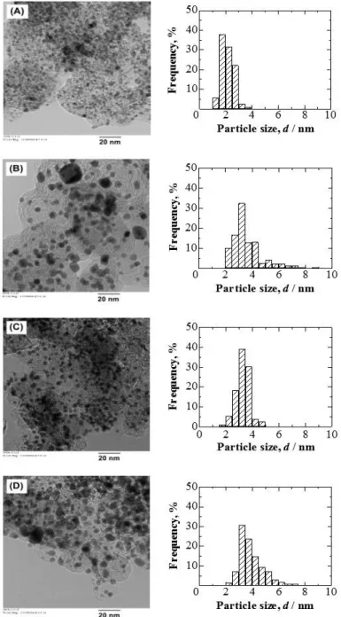
commercial catalysts of c-Pt/C, c-Pt3Co/C and c-Pt2Ru3/C. Figure 2-1 shows TEM images
and particle size distribution histograms of these catalysts. Compared with c-Pt3Co/C and
c-Pt2Ru3/C, the PtxAL–PtCo nanoparticles were uniformly dispersed on the carbon black
support, and their size distributions were fairly narrow, features credited to the use of nanocapsule method. The typical properties of the catalysts are shown in Table 2-1.
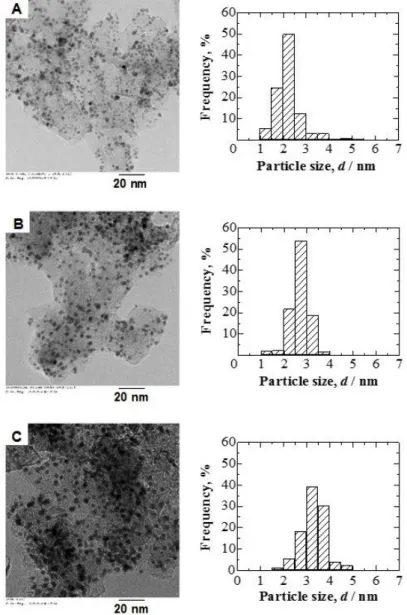
For screening the best catalysts, the effect of the nonprecious metal species M (M = Fe, Co, and Ni) in PtxAL−PtM/C on the catalytic properties was then examined. Figure 2-2
shows TEM images and particle size distribution histograms of PtxAL−PtFe/C,
PtxAL−PtCo/C, and PtxAL−PtFe/C catalysts. For all three catalysts, the PtxAL−PtM
nanoparticles were uniformly dispersed on the support. The properties of these catalysts are summarized in Table 2-2. The mean particle size for these Pt-skin catalysts was shown to be similar (around 3.0 nm).
18
Afterwards, the effect of the particle size of PtxAL−PtCo/C catalyst was examined.
Monodisperse PtxAL−PtCo catalysts with different particle sizes were prepared by the
nanocapsule method. Figure 2-3 shows TEM images and particle size distribution histograms for all catalysts. The properties of these catalysts are presented in Table 2-3. The average particle size dTEM of PtxAL−PtCo/C (A), PtxAL−PtCo/C (B), and PtxAL−PtCo/C (C)
were determined to be 2.2 nm, 2.7 nm, and 3.3 nm, respectively.
Finally, effect of the core alloy composition was examined. The Pt-skin−Pt100-XCoX/C
catalysts (X = 20, 25, 33, 50 and 60) were prepared in the same manner as stated above. Figure 2-4 shows TEM images and particle size distribution histograms of the catalysts with different core-metal compositions. The properties of these catalysts are summarized in Table 2-4. There appeared to be a monotonic increase in Co atomic ratio from catalyst A to E (Figure 2-4) while their particle sizes were found to be nearly identical (ca. 3.0 nm).
19
Table 2-1 Typical properties of PtxAL−PtCo/C, c-Pt3Co/C, c-Pt2Ru3/C, and c-Pt/C catalysts.
Catalyst dTEM / nm Metal loading, wt % Composition, atom %
PtxAL−PtCo/C 3.3 ± 0.5 32.7 67.2-Pt 32.8-Co
c-Pt3Co/C 3.3 ± 1.3 51.4 73.7-Pt 26.3-Co
c-Pt2Ru3/C 3.5 ± 0.9 53.0 39.9-Pt 60.1-Ru
c-Pt/C 2.2 ± 0.5 46.1 46.1-Pt NA
Figure 2-1 TEM images and particle size distribution histograms of (A) c-Pt/C, (B) c-Pt3Co/C, (C) PtxAL−PtCo/C, and (D) c-Pt2Ru3/C catalysts.
20
Table 2-2 Typical properties of PtxAL−PtFe/C, PtxAL−PtCo/C, and PtxAL−PtNi/C catalysts.
Catalyst dTEM / nm Metal loading, wt % Composition, atom %
PtxAL−PtFe/C 2.9 ± 0.4 31.5 73.2-Pt 26.8-Fe
PtxAL−PtCo/C 3.3 ± 0.5 32.7 67.2-Pt 32.8-Co
PtxAL−PtNi/C 3.2 ± 0.4 40.8 70.8-Pt 29.2-Ni
Figure 2-2 TEM images and particle size distribution histograms of (A) PtxAL−PtFe/C,
21
Table 2-3 Typical properties of the PtxAL-PtCo/C with different particle sizes.
Catalyst dTEM / nm Metal loading, wt %
Composition, atom %
Pt Co
PtxAL−PtCo/C (A) 2.2 ± 0.5 29.4 88.6 11.4
PtxAL−PtCo/C (B) 2.7 ± 0.4 30.4 68.6 31.4
PtxAL−PtCo/C (C) 3.3 ± 0.5 32.7 67.2 32.8
Figure 2-3 TEM images and particle size distribution histograms of PtxAL−PtCo/C with
22
Figure 2-4 TEM images and particle size distribution histograms of (A) PtxAL−Pt80Co20/C, (B) PtxAL−Pt75Co25/C, (C) PtxAL−Pt67Co33/C, (D) PtxAL−Pt50Co50/C and
23
Table 2-4 Typical properties of the PtxAL‒Pt100-XCoX/C catalysts (X = 20, 25, 33, 50 and
60).
Catalyst dTEM / nm Metal loading, wt %
Composition, atom % Pt Co PtxAL−Pt80Co20/C 3.2 ± 0.5 35.5 84.3 15.7 PtxAL−Pt75Co25/C 2.9 ± 0.5 33.0 79.4 20.6 PtxAL−Pt67Co33/C 2.8 ± 0.5 33.8 77.7 22.3 PtxAL−Pt50Co50/C 3.3 ± 0.5 32.7 68.6 31.4 PtxAL−Pt40Co60/C 3.1 ± 0.5 36.0 51.0 49.0
24
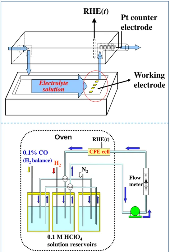
The electrochemical measurement was performed using a multi-channel flow electrode (M-CFE) cell. Figure 2-5 shows the experimental setup of the M-CFE cell and flow circuit of electrolyte solution. The CFE cell is operated as a closed system with controlled H2 or
CO concentration, such that the kinetically controlled current density can be accurately evaluated.
The catalyst powder was ultrasonically dispersed in 2 mL of ethanol (99.5% ethanol). The Au electrode (flow direction length 1 mm × width 4 mm) served as the substrate for the supported catalyst. An aliquot of 2 μl catalyst suspension was pipetted onto the Au substrate to make the working electrode. The amount of each catalyst was maintained at a constant loading of carbon support of 11 µg cm−2, which corresponds to a height of approximately two monolayers of the carbon black particles. 0.5 μl of a diluted Nafion solution (0.2 wt%) was pipetted on the catalyst layer to yield an average film thickness of 0.075 µm. Thickness of the Nafion film was calculated from its mass and the electrode surface area assuming a dry Nafion density of 1.98 g cm-3. The Nafion-coated electrode was dried under ethanol
vapor pressure at room temperature. Finally, the Nafion-coated electrode was heated at 130°C for 30 min in air.
A platinum wire was used as the counter electrode. A reversible hydrogen electrode RHE (t), maintained at the same temperature as that of the cell, was used as the reference electrode. All electrode potentials were controlled by an eight-channel potentiostat HA1010mM8 (Hokuto Denko Co., Japan) with respect to the RHE (t).
The electrolyte solution, 0.1 M HClO4, was prepared from reagent grade chemicals
(Kanto Chemical Co.) and Milli-Q water, and purified in advance with conventional pre-electrolysis methods [3,4]. The electrolyte solution was saturated with N2, pure H2, and
CO-containing H2 (1000 ppm CO, Sumitomo Seika, Japan) bubbling in three separate
25
Figure 2-5 Schematic diagram of the M-CFE cell (upper) and the flow circuit of electrolyte solution (lower). The temperature of electrolyte solution reservoirs was controlled by a heater from 20 to 90 °C.
0.1% CO
(H2 balance) Flow meter RHE(t)N
2H
2 CFE cellOven
0.1 M HClO
4solution reservoirs
Pt counter
electrode
RHE(t)
Electrolyte
solution
Working
electrode
26
2.2.2 Evaluation of CO-Tolerant HOR Activity and Durability
Prior to the HOR experiments, the working electrode was electrochemically stabilized by repetitively sweeping the potential from 0.05 to 1.00 V for c-Pt/C, c-Pt3Co/C, and
PtxAL−PtCo/C, and from 0.05 to 0.80 V for c-Pt2Ru3/C at a scan rate of 0.50 V s-1 in 0.1 M
HClO4 solution deaerated with N2 gas at 70 °C until the voltammogram reached a steady
state (typically 20 cycles). The electrochemical active area (ECA) of Pt was determined from the hydrogen desorption charge in the anodic voltammogram at the sweep rate of 0.1 V s-1, assuming that 1 cm2 of smooth Pt required 210 µC.
The hydrodynamic voltammograms for the HOR at the CO-free working electrode were recorded by sweeping the potential from 0.0 to 0.1 V at a scan rate of 1.0 mV s-1 in
H2-saturated 0.1 M HClO4. The mean flow rate of electrolyte (Um) was 18 cm s-1. The
kinetically-controlled current Ik at a given potential E was determined from the
hydrodynamic voltammograms by use of the following equation [5-7],
1/I = 1/Ik + 1/IL (2-1)
where I is the observed current at a given potential and IL is the diffusion limiting current.
In order to minimize the mass transport limitation, we chose 20 mV vs. RHE to compare the HOR activity. The kinetically-controlled mass activity, MAk, at 20 mV vs. RHE for the
HOR was determined by normalizing Ik to the total metal weight. The area-specific kinetic
current density jk were obtained based on Ik and the ECA.
Carbon monoxide was adsorbed on the working electrode by flowing 0.1 M HClO4
solution saturated with 1000 ppm CO (H2-balance) at the mean flow rate of 18 cm s-1 for
various time intervals (tad) while holding the potential at 0.05 V. The HOR activity at the
CO-adsorbed electrode surface was examined by recording hydrodynamic voltammograms under a flow of pure H2-saturated 0.1 M HClO4 solution in the same manner as described
above. Finally, a CO-stripping voltammogram was recorded at the sweep rate of 0.10 V s-1 in N2-saturated 0.1 M HClO4 to determine the coverage of CO on the catalyst surface.
The CO coverage (θCO) as the site occupation of Pt surface was calculated based on the
following equation, regardless of the type of COad, e.g., linear (on-top), bridged, or the
derivatives,
θCO = 1 − (∆QH/∆QH°) (2-2)
where ∆QH and ∆QH° are the hydrogen-desorption charges with and without COad,
respectively [5,6].
27
s-1 in N2-saturated 0.1 M HClO4 at70 °C. After a given number of cycling, the HOR activity
without the presence of CO and with respect to 30 min CO-poisoning in 1000 ppm CO/H2
was examined by using the means as described above.
2.3 Results and Discussion
2.3.1 HOR Activity and Durability on Stabilized Pt-Skin/PtCo Alloy Catalyst without and with the Adsorbed CO
2.3.1.1 HOR activity on CO-free electrode
Table 2-5 summarizes the MAk values of the catalysts toward the HOR measured in pure
H2-saturated 0.1 M HClO4 solution at 70 °C and 90 °C. The PtxAL−PtCo/C catalyst was
found to exhibit the highest MAk for the HOR, 848 A g−1 at 70°C, which was about 1.5
times higher than that of c-Pt/C, 2.0 times higher than that of c-Pt2Ru3/C, and 2.1 times
higher than that of c-Pt3Co/C. All of the catalysts showed a decrease in MAk at 90 °C
compared to that at 70°C, which is ascribed mainly to the decreased solubility of H2 in the
solution at high temperature, but the trend of the MAk values was unchanged [5,6].
Table 2-5 Kinetically-controlled mass activity, MAk, at 20 mV vs. RHE for the HOR of
pure H2 at Nafion-coated catalysts at 70 °C and 90 °C.
Catalyst MAk / A gmetal −1 70 °C 90 °C PtxAL−PtCo/C 848 790 c-Pt/C 563 516 c-Pt2Ru3/C 425 388 c-Pt3Co/C 395 339
The area-specific kinetic current densities jk were also determined from the Ik values and
the ECA, and the Pt2AL−PtCo/C catalyst exhibited the highest value, 1.81 mA cm−2 at 70 oC,
about twice as high as that for c-Pt/C (0.93 mA cm-2), which has been the best monometallic catalyst for the HOR so far. The values for c-Pt2Ru3/C and c-Pt3Co/C were
28 2.3.1.2 HOR activity in the presence of CO
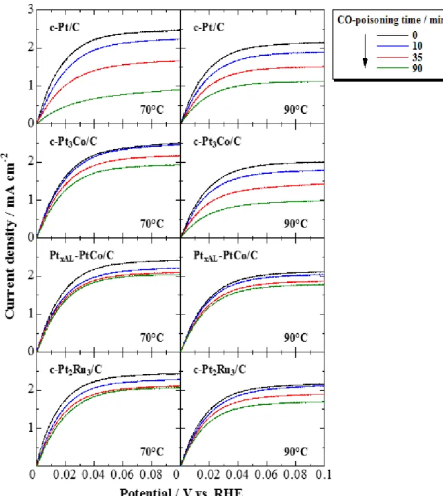
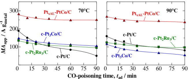
After CO adsorption, the limiting currents for the HOR at all catalysts decreased due to the blocking of the Pt active sites by the adsorbed CO, COad, as shown in Figure 2-6. Thus,
it is not possible to obtain the true Ik values, and therefore, for convenience, an apparent
mass activity at 20 mV was used, MAapp, as a measure of the CO tolerance, by directly
using the measured current I divided by the metal mass. The changes in the MAapp values of
these catalysts measured in H2-saturated 0.1 M HClO4 after CO adsorption for various time
29
Figure 2-6 Hydrodynamic voltammograms for the HOR in H2-saturated 0.1 M HClO4
solution at Nafion-coated c-Pt/C, c-Pt3Co/C, PtxAL−PtCo/C, and c-Pt2Ru3/C electrodes
with various time of CO-poisoning in 1000 ppm CO/H2 at 70 °C and 90 °C. The current
30
The MAapp for c-Pt/C measured at 70 oC decreased rapidly with increasing tad. In contrast,
the decreases in MAapp were slower at c-Pt3Co/C, c-Pt2Ru3/C, and, particularly, at
PtxAL−PtCo/C. With elevation of the temperature to 90 °C, the CO tolerance for all of the
catalysts improved, except that c-Pt3Co/C showed inferior tolerance compared with that at
70 °C.
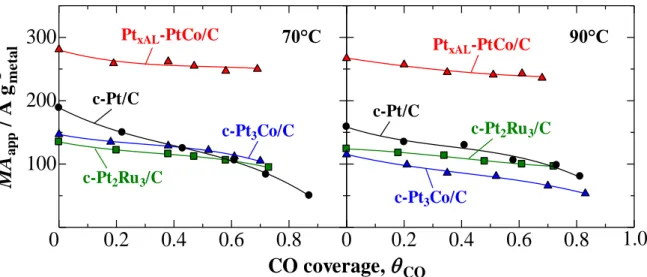
To discuss the CO tolerant mechanism of these catalysts, we focus on the dependence of MAapp on CO coverage, θCO. The values of θCO at a given tad in Fig. 2-7 were determined
approximately from the number of Pt metal sites blocked by CO, irrespective of the type of Figure 2-7 Change in the MAapp with CO-poisoning time (tad) for c-Pt/C, c-Pt3Co/C,
PtxAL−PtCo/C, and c-Pt2Ru3/C at 70 oC and 90 oC.
15
30
45
60
75
90
100
200
300
0
MA a p p / A g -1CO-poisoning time, t
ad/ min
c-Pt2Ru3/C c-Pt3Co/C c-Pt/C c-Pt3Co/C c-Pt2Ru3/C c-Pt/C 90°C 70°C metal
15
30
45
60
75
90
0
PtxAL-PtCo/C PtxAL-PtCo/C
Figure 2-8 CO-stripping voltammograms at c-Pt/C and PtxAL-PtCo/C electrodes with
different time on exposure to CO measured in N2 saturated 0.1 M HClO4 solution at 70 oC. The potential sweep rate was 0.10 V s-1.
0
0.2
0.4
0.6
0.8
1.0
-1
0
1
C
u
r
r
e
n
t d
e
n
si
ty /
mA
c
m
-2Potential / V vs. RHE
Potential / V vs. RHE
c-Pt/C PtxAL-PtCo/C tad = 0 min tad = 10 min tad = 35 min tad = 90 min
0
0.2
0.4
0.6
0.8
1.0
-1
0
1
31
bonding, e.g., linear (on-top), bridged, or others (see eq. [2-2]). As seen from the CO-stripping voltammograms (Figure 2-8), both c-Pt/C and PtxAL−PtCo/C showed
increases in CO oxidation charge (increased θCO) while decreases in hydrogen desorption
charge with increasing CO adsorption time tad, suggesting that the Pt active sites available
for hydrogen adsorption decreased due to a blocking of CO. Resulting from a strong blocking effect of CO, the value of MAapp at c-Pt/C decreased gradually with increasing θCO
at 70 °C (Figure 2-9). In contrast, the Pt2AL−PtCo/C, c-Pt2Ru3/C, and c-Pt3Co/C catalysts
exhibited excellent CO tolerance at 70 °C, though appreciable amounts of CO virtually adsorbed on the surface, suggesting that the HOR active sites were not so rigidly blocked by COad, which might be due to its enhanced mobility. It is noteworthy that the CO
tolerance of PtxAL−PtCo/C was higher than that of c-Pt2Ru3/C, e.g., the MAapp value for
PtxAL−PtCo/C with θCO > 0.5 reached a nearly constant value of 88% of that at the CO-free
surface, whereas that for c-Pt2Ru3/C still decreased to 73% at θCO = ca. 0.7.
At 90 °C, high CO tolerance at the PtxAL−PtCo/C catalyst was maintained: the MAapp
value at θCO > 0.6 was as high as 90% of that at θCO = 0. For c-Pt2Ru3/C, the CO tolerance
was, as expected, improved by elevating the temperature to 90 °C, so that the dependence of MAapp on θCO became smaller than that at 70 °C. However, at the identical coverage θCO
= 0.7, the value of MAapp for PtxAL−PtCo/C was about 2.5 times higher than that for
c-Pt2Ru3/C. These results convince us that Pt2AL−PtCo/C is a superior CO-tolerant anode
catalyst in the practical temperature range, which would make it possible to decrease the amount of platinum-group metals (Pt + Ru) compared with the case of the conventional
Figure 2-9 Dependence of MAapp at 20 mV vs. RHE on θCO for PtxAL−PtCo/C, c-Pt/C,
c-Pt3Co/C and c-Pt2Ru3/C electrodes measured in H2-saturated 0.1 M HClO4 solution at
70 oC and 90 oC.
0.2
0.4
0.6
0.8
100
200
300
0
c-Pt2Ru3/C c-Pt/C c-Pt2Ru3/C c-Pt3Co/C0
0.2
0.4
0.6
0.8
MA
a p p/
A
g
-1CO coverage,
PtxAL-PtCo/C Pt xAL-PtCo/C c-Pt3Co/C c-Pt/C 70°C 90°C1.0
metal CO32 c-Pt2Ru3/C catalyst.
The CO tolerance at c-Pt3Co/C was comparable to that at c-Pt2Ru3/C at 70 °C, whereas it
degraded at 90 °C. The dependence of MAapp at c-Pt3Co/C on θCO at 90°C was very similar
to that of c-Pt/C, suggesting that Pt3Co became Pt-like, probably caused by severe Co
corrosion at high temperature [5,6]. In contrast, high CO tolerance was maintained for the PtxAL−PtCo/C catalyst at 90 °C, indicating that the stabilized Pt skin layer was able to
protect the underlying alloy and maintain the modified electronic state for weakening CO adsorption.
2.3.1.3 CO-tolerant HOR durability with respect to potential cycling
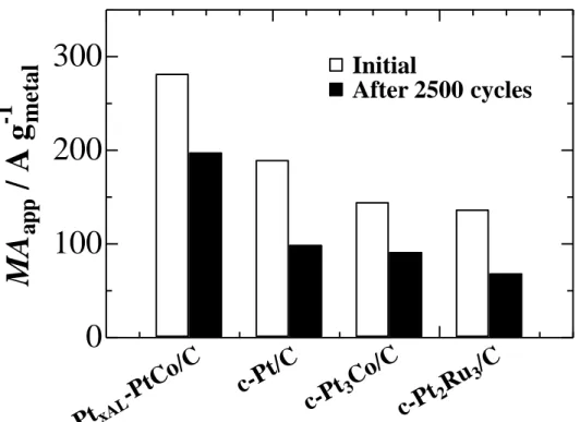
Next, the robustness of these catalysts upon a consecutive potential cycling was examined which simulates the repeated exposure of the fuel cell anode to reformate gas and air during daily start/stop cycles. As an accelerated protocol, the catalysts were subjected to repeated potential cycling between 0.02 and 0.95 V at a scan rate of 20 mV s−1 at 70 °C in N2-purged 0.1 M HClO4. Figure 2-10 shows changes in the MAapp values for the HOR of
pure H2 for these catalysts before and after 2500 cycles. It is clearly seen that Pt2AL−PtCo/C
still exhibited the highest MAapp (ca. 80% retention of the initial value) after 2500 cycles,
which was 2.2 and 2.9 times higher than those of c-Pt/C and c-Pt2Ru3/C, respectively. The
worst degradation was seen for c-Pt2Ru3/C (50% retention), probably due to severe Ru
dissolution under oxidative conditions. In contrast, the decrease in MAapp at c-Pt/C can be
ascribed to a loss of the electrochemical active area as a result of agglomeration and/or a dissolution/re-deposition process during the potential cycling [8,9]. Thus, the stabilized Pt-skin/PtCo layer seems to be robust to this degradation mode.
33
Figure 2-10 Changes in MAapp for the HOR of pure H2 at PtxAL−PtCo/C, c-Pt/C,
c-Pt3Co/C, and c-Pt2Ru3/C electrodes before and after potential cycling in N2-purged 0.1
M HClO4 solution at 70 °C for 2500 cycles between 0.02 and 0.95 V at 20 mV s-1.
0
100
200
300
The 2
ndtime
The 2
ndtime
c-Pt/C
c-Pt/C
c-Pt
3Co/C
c-Pt
2Ru
3/C
c-Pt
2Ru
3/CB
c-Pt/C
c-Pt
3Co/C
c-Pt
2Ru
3/C
c-Pt
3Co/C
c-Pt
2Ru
3/C
Initial
After 2500 cycles
met
al
0
100
200
300
400
MA
app
for HOR of pure H
N=0
2
N=2500
N=0
N=2500
The 1
sttime
The 1
sttime
Pt
xAL-PtCo
/C
Pt
2AL-PtCo
/C
Pt
2AL-PtCo/CB
Pt
2AL-PtCo
/C
MA
app
for HOR after 30 min CO-poisoning
65%
48%
56%
36%
0
100
200
300
63%
Initial
After 2500 cycles
0
100
200
300
400
MA
a
p
p
/
A
g
-1
MA
a
p
p
/
A
g
-1
me
ta
l
47%
57%
32%
0
100
200
300
The 2
ndtime
The 2
ndtime
c-Pt/C
c-Pt/C
c-Pt
3Co/C
c-Pt
2Ru
3/C
c-Pt
2Ru
3/CB
c-Pt/C
c-Pt
3Co/C
c-Pt
2Ru
3/C
c-Pt
3Co/C
c-Pt
2Ru
3/C
Initial
After 2500 cycles
met
al
0
100
200
300
400
MA
app
for HOR of pure H
N=0
2
N=2500
N=0
N=2500
The 1
sttime
The 1
sttime
Pt
xAL-PtCo
/C
Pt
2AL-PtCo
/C
Pt
2AL-PtCo/CB
Pt
2AL-PtCo
/C
MA
app
for HOR after 30 min CO-poisoning
65%
48%
56%
36%
0
100
200
300
63%
Initial
After 2500 cycles
0
100
200
300
400
MA
a
p
p
/
A
g
-1
MA
a
p
p
/
A
g
-1
me
ta
l
47%
57%
32%
34
The CO-tolerant HOR activity of these catalysts after potential cycling degradation was further examined. Figure 2-11 shows MAapp values for the HOR upon 30 min CO-poisoning
before and after degradation. The CO-tolerant MAapp at PtxAL−PtCo/C was maintained at ca.
80% of the initial value after 2500 cycles, which was 3.9 times higher than that of c-Pt2Ru3/C. The CO-tolerant MAapp decreased drastically at c-Pt2Ru3/C (55% loss) after
2500 cycles, which can be ascribed to the severe Ru loss at high potentials, as stated above. To resolve the dilemma in using dissolution-prone Ru, Hsieh et al. have proposed Pt shell/Ru core anode catalysts [10]. They examined the performances of membrane-electrode assemblies (MEAs) at 75 °C by the use of H2 fuel with 10 ppm CO.
Even with 1.5% air bleed to the anode, the performance, as measured by the current density at 0.65 V, decreased by ca. 40% with CO compared to that with pure H2. A stability test in
the MEA after 2500 cycles between 0.02 and 0.95 V showed negligible decline in the cell voltage, similar to the present work, since the retention of 80% of MAapp at PtxAL−PtCo/C
corresponds to only 3 mV loss based on a Tafel slope of 30 mV decade−1 [5].
Other approaches have been also proposed to hamper Ru dissolution or to stabilize Pt-Ru, e.g., utilizing functionalized supports [11], stabilization with ruthenium oxide in nanosheet form [12], the incorporation of Au [13]. However, for the sake of cost reduction, our proposed PtxAL−PtCo/C catalysts, without the use of Ru, appears to be more promising for
practical use as robust hydrogen anode catalyst in reformate gas fuel cells.
Figure 2-11 Changes in MAapp for the HOR with 30 min CO-adsorption in 1000 ppm
CO/H2 at PtxAL−PtCo/C and c-Pt2Ru3/C electrodes before and after potential cycling in
N2-purged 0.1 M HClO4 solution at 70 °C for 2500 cycles.