Study on main chain structure of anion
conductive polymers for alkaline fuel cells
A Doctoral Thesis
Presented to
Interdisciplinary Graduate School of Medicine and Engineering
University of Yamanashi
March 2017
Hideaki Ono
1.1 Back ground ... 1
1.2 Anion conductive membrane ... 2
1.2.1 Alkaline fuel cells using anion conductive membrane ... 2
1.2.2 Role and issue of anion conductive membrane in alkaline fuel cells ... 3
-1.3 Approaches to improve stability and conductivity of anion conductive membrane ... 4
1.3.1 Degradation mechanism of anion conductive membranes ... 4
1.3.2 Investigation involving ion exchange groups ... 6
1.3.3 Investigation involving main chain structure ... 8
1.3.4 Object of this study ... 9
References ... 10
-Chapter 2. Synthesis and properties of anion conductive block copolymers including fluorine or nitrile compounds 2.1 Introduction ... 14
2.2 Experimental ... 15
2.3 Results and discussion ... 19
2.3.1 Synthesis and chloromethylation of model oligomers ... 19
2.3.2 Synthesis of QPEbl4 ... 23
-2.3.3 Water uptake, hydroxide ion conductivity, and morphology of QPE-bl-4 membranes ... 29
2.3.4 Stability of QPEbl4 membranes ... 31
2.4 Conclusions ... 34
3.1 Introduction ... 36
3.2 Experimental ... 37
3.3 Results and discussion ... 41
3.3.1 Synthesis of copolymers and membranes ... 41
3.3.2 Morphology of the quaternized membrane ... 49
3.3.3 Water uptake and ion conductivity ... 50
3.3.4 Alkaline stability ... 53
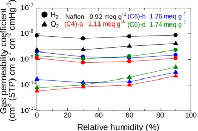
3.3.5 Gas permeability ... 55
3.3.6 Mechanical properties ... 56
3.3.7 Fuel cell performance ... 58
3.4 Conclusions ... 59
References ... 60
-Chapter 4. Partial replacement of the perfluoroalkyl group with alkyl groups 4.1 Introduction 4.2 Experimental ... 63
4.3 Results and discussion ... 70
4.3.1 Synthesis of terpolymers and membranes ... 70
4.3.2 Water uptake and ion conductivity ... 73
4.3.4 Alkaline stability ... 78
4.4 Conclusions ... 81
hexyltrimethylammonium groups
5.1 Introduction ... 84
5.2 Experimental ... 85
5.3 Results and discussion ... 88
5.3.1 Synthesis of QPAF4 copolymers and membrane preparation ... 88
5.3.2 Water uptake and ion conductivity ... 91
5.3.3 Gas Permeability ... 93
5.3.4 Mechanical properties ... 94
5.3.5 Alkaline Stability ... 96
5.4 Conclusions ... 99
References ... 100
-Chapter 6. General conclusions and future prospects 6.1 General conclusions ... 102 6.2 Future prospects ... 104 List of publications ... 105 List of Patents ... 107 Meeting abstracts ... 108 Acknowledgement ... 110
-- 1 --
Chapter 1.
General introduction
1.1 Back ground
Japan is an island country geographically isolated from the other continents and surrounded by the sea, therefore it is poor in natural resources such as fossil fuels. The Great East Japan Earthquake and the catastrophic accident at Fukushima nuclear power plant of March 11 2011, led to concerns on the safety of nuclear power generation. Therefore primary energy supply from the nuclear power shifted to thermal power and
its ratio achieved 94.6% in 2013.1 The thermal power is generated from fossil fuels
relying on importation from abroad, thus self-sufficiency ratio in the primary energy
supply was only 6.1% in 2013.1 The strong dependence on fossil fuels include risks
that economic activities might be stagnant if the fossil fuels suppling from overseas stopped. The risk is only not for Japan. We should notice that the earth is also isolated from the other planets and surrounded by space, thus the natural resources are limited. In the past 50 years, world human population rapidly increased from 2.5 to 7.3 billion
and is expected to reach 9.7 billion in 2050.2,3 Energy demand and fossil fuel
consumption will increase in association with such rapid growth of population, as well as economy. However large consumption of fossil fuels has induced serious
environmental problems such as global warming and depletion of fossil fuels.4,5 In
such situation, renewable energies such as solar, hydro, wind power generation are
essential for sustainable development.6-8 However, there are many problems to use
them as the electrical base load due to irregular availability of such renewable energy
resources depending on natural conditions.9 The one of the promising candidate
systems for stable energy supplying is storage of renewable energy as chemicals (such as hydrogen) and then convert them to electricity on site. In such situation, fuel cells
have been attractive as the effective energy conversion device.10
Fuel cell is long historical energy conversion devise and the first one was carried out by Sir William Robert Grove in 1839 which generated electric energy from the
- 2 -
electrochemical reaction of hydrogen and oxygen.11 Compared with current
internal-combustion engines, fuel cells have some advantages to utilize the energy ubiquitously in modern society such as silentness, high energy density, compactness and no emissions of pollutants.12,13 Fuel cells can be classified by their electrolyte and operation temperature. Among them, polymer electrolyte membrane fuel cells (PEFCs) are operable around room temperature to 90 ºC, which make them attractive for wide variety of applications including power plant, vehicles, stationary energy applications. and portable electronics.14-18
In PEFCs, polymer electrolyte membrane is one of the key materials. Currently, perfluorinated proton conductive membrane is mostly used in PEFCs and Nafion (Du Pont) is well known as benchmark of the membrane due to its high proton conductivity
and chemical and mechanical stability.19,20 However, electrodes in PEFCs using proton
conductive membranes are exposed to acidic conditions due to strongly acidic nature of the membrane. Such acidic conditions require expensive platinum as the electrocatalyst, which is a serious drawback for wide-spread practical applications. In such situation, one of the attractive options is replacing the proton conductive
membrane with anion conductive membrane.21
1.2 Anion conductive membrane
1.2.1 Alkaline fuel cells using anion conductive membrane
The anion conductive membranes have recently attracted attention for a wide variety of applications including water electrolyzer, desalination, redox flow batteries and fuel
cells.22-27 The required performance for anion conductive membrane is similar but
slightly depends on its application. For example, in water electrolyzers the membrane should have low hydrogen permeability, durability in high potential and toughness to endure differential pressure between water and gas phase. In desalination high anion conductivity is required for rapid treatment of sodium chloride. In redox flow batteries, the membrane should be durable for reductant and oxidant agents feed as fuel. Particularly, anion conductive membranes provide alkaline fuel cells with great advantages over those with proton conductive membranes. Comparison of the
- 3 -
principles of PEFCs with proton conductive membrane and alkaline fuel cells with anion conductive membrane are shown in Fig. 1-1, in which hydrogen and oxygen are supplied. In the alkaline fuel cell using anion conductive membrane, oxygen is supplied to the cathode and reduced by electrons and water to hydroxide ion. On the other hand, hydrogen is supplied to the anode and oxidized to water and electrons by hydroxide ion which migrates through the anion conductive membrane from the cathode. Since the conductor ion is hydroxide ion in alkaline fuel cells, the electrode is exposed to basic conditions which enable to use of abundant transition metals (Ni, Co, Fe, etc.) and facilitate the oxygen reduction reaction. Such advantages expand availability for discovering inexpensive and high activity of electrocatalysts alternative to Pt and the potential advantages make alkaline fuel cells using anion conductive
membranes attractive and promising choice.28-30 However there are no standard anion
conductive membranes while there have been considerable efforts in developing better performing anion conductive membranes because of rather low ion conductivity and insufficient stability under the basic conditions.
1.2.2 Role and issue of anion conductive membrane in alkaline fuel cells
Anion conductive membranes have many roles in the fuel cell such as anion conduction, gas and electron barrier, and water management. The anion conductivity is directly related with the fuel cell performance and should be as high as or higher
hopefully than 100 mS cm-1 to minimize resistive losses.31 The conductivity is from the
Figure 1-1. Principles of fuel cells using proton exchange membrane and
- 4 -
product of density, charge and mobility of carrier ions. Therefore, increase of ion density by increasing ion exchange capacity (IEC) is one of the approaches, however, higher IEC often causes higher water uptake leading to the loss of mechanical property and occasionally dissolution in water. Construction of hydrophobic and hydrophilic phase separated morphology is another promising methods to improve the mobility of
ions.32 The aggregation of hydrophilic moieties increases local ion density whereas
aggregation of hydrophobic moieties suppresses excess swelling. Carrie ions in anion conductive membrane are generally hydroxide ions and they have much bigger mass and radius than those of electron. Therefore, electron conduction is considered as quantum-mechanical phenomenon, whereas ion conduction is accompanied by mass
transfer phenomenon.33 In addition, in typical ionomer membranes, hydrated and
dissociated anions are single charge carriers since the counter cationic groups are tethered onto polymer matrix.
The major issues of anion conductive membrane involve strong nucleophilicity of the carrier hydroxide ion can trigger the degradation of ion exchange groups and the polymer main chain followed by decreasing anion conductivity and mechanical property. For successful commercialization, the first and essential challenge is long term durability of anion conductive membrane with high anion conductivity and good mechanical property.
1.3 Approaches to improve stability and conductivity of anion conductive membrane
1.3.1 Degradation mechanism of anion conductive membranes
To create highly durable anion conductive membrane, it is important to study degradation mechanism under alkaline condition generally in 1 – 3 M KOH solution at
60 – 80 ºC.28 At first, degradation mechanism of trimethylammonium groups is
described because it is the most common ion exchange group and directly related to decreasing of anion conductivity. One of the key degradation pathways is Hoffman elimination (Fig. 1-2). In this reaction, hydroxide anion attack to a hydrogen atom on the β-carbon relative to the nitrogen atom. Generally speaking, trimethylammonium
- 5 -
groups without β-positioned hydrogens can escape this degradation pathway therefore many reports apply benzyl trimethylammonium groups as ion exchange groups. However it is well-known that the benzyl trimethylammonium groups also decompose under alkaline conditions at elevated temperature by direct nucleophilic substitution reaction (Fig. 1-3).21
In alkaline conditions, applicable main chain structures are also limited. However evaluation of the degradation mechanism on main chain is more complicated than ion exchange groups because the degradation does not occur at only specific positon and the reactivity is strongly dependent on electronic environment of chemical linkages. In addition, side reaction (such as cross linking) associated with the degradation often lower the polymer solubility which precludes quantitative chemical analysis by NMR. Therefore there are few papers focusing on the degradation of main chain of anion
Figure 1-2. Degradation of trimethylammonium group by Hoffman elimination.
- 6 -
conductive membranes. Mechanical degradation of polyvinylidene fluoride was reported even under diluted 0.01 M NaOH at r.t. due to dehydrofluorination (Fig.
1-4).34 Polycarbonate and polyethylene terephthalate are also well-known to
experience main chain cleavage under alkaline conditions.35,36 It was reported
independently that main chain degradation of quaternized poly(arylene ether)s was triggered by the degradation of phenylene ether groups by attacking of hydroxide ions,
leading to main chain degradation of the poly(arylene ether)s.37-40 (Fig. 1-5) Hibbs
reported that ketones adjacent to the phenylene ring can take part in the degradation reaction.41
1.3.2 Investigation involving ion exchange groups
To address the low anion conductivity and insufficient stability, various kinds of ion
Figure 1-4. Degradation of polyvinylidene fluoride by dehydrofluorination.
Figure 1-5. Possible degradation of poly(arylene ether)s.
O O S O O O S O O N+ N+ R R R R OH -OH HO O O F F F F F F F F OH -N+ N+ O F F F F F F F F N+ N+ ONa NaO
- 7 -
exchange groups instead of benzyl trimethylammonium, such as guanidinium, imidazolium, sulfonium, phosphonium, and metal cations have been
reported.42-51Noonan et al. reported that tetrakis(dialkylamino)phosphonium cation
attached on polyethylene backbone retained its hydroxide conductivity (ca. 18 mS cm-1
at 22 ºC) in 1 M KOH at 80 ºC for 528 h.52
In general, long alkyl tethered ammonium groups have a hydrogen atom on the β-carbon relative to the nitrogen atom inducing Hoffmann elimination however several reports and computational study suggested that the better alkaline stability of the long alkyl tethered ammonium groups. Li et al. reported that long alkyl chain tethered benzyl ammonium groups on poly(2,6-dimethyl phenylene oxide) backbones retained mechanical property and bicarbonate conductivity in 1 M NaOH at 80 ºC for 2000 h likely due to the steric effects of the long alkyl chains surrounding the quaternary
ammonium center.53 Long et al. reported DFT study involving substituted
trimethylammonium cations, in which the Hofmann elimination is the most vulnerable pathway for normal alkylated ammonium groups however the barrier dramatically
increased by increasing of the number of carbon atoms in the chain from 2 to 6.54 Lee
et al. reported fluorene-based polymers with trimethylammonium groups spaced by alkylene (six carbons) between the fluorene and the ammonium groups. The alkaline
stability was evaluated by 1H NMR and titration, implying the excellent chemical
stability under 1 M NaOH solution as 80 ºC for 720 h. However the membrane became fragile after 168 h probably attributed to the high IEC of the membrane and
morphological change.55 The opposite opinions have also been reported about the
effect of alkylene spacer. Parrondo et al. have reported poly(phenylene oxide) based polymer with several kinds of cationic groups (including trimethylammonium groups) spaced by alkylene (six carbons) between main chain and cationic groups. The
post-test analyses of 1H NMR and titration suggested that the hexyl spaced
trimethylammonium with poly(phenylene oxide) degrade in alkaline condition (1 M
KOH at 60 ºC for 720 h) and it does not represent any improvement over the anion
- 8 -
1.3.3 Investigation involving main chain structure
The alkaline stability of the main chain is also essential for anion conductive membrane. One of the main strategies for improving the alkaline stability of the main chain is eliminating of heteroatom linkages such as ether, sulfone and ketone groups since these heteroatom groups are likely to experience chemical degradation under basic conditions. Hibbs have reported poly(phenylene)-based anion conductive
membranes with benzyl trimethylammonium groups.57 Structural analysis by FTIR for
the membrane which was treated in 0.5 M NaOH at 80 ºC for 100h exhibited cation
degradation however the backbone was stable.38 More recently, the poly(phenylene)
attached with various ion exchange groups was reported. The alkaline stability was carried out in 4 M KOH at 90 ºC for 336 h and the post-test analyses were carried out in chloride ion conductivity and titration measuring IEC because all samples were insoluble after testing. The membrane functionalized with C6 alkylene spaced trimethylammonium groups results in greater stability than that of benzyl trimethylammonium functionalized membrane despite the possibility of Hofmann elimination which are not possible in the latter one.41
Morphological studies by controlling the main chain structure have been reported to improve anion conductivity and mechanical stability. Lai et al. developed phenolphthalein-containing crosslinked poly(arylene ether sulfones) anion conductive membrane to improve dimensional stability and aggregation of the ion clusters leading to hydrophobic/hydrophilic phase-separated morphology and ion conducting channels.
The resulting membrane with IEC = 2.11 meq g-1 showed high hydroxide ion
conductivity of 143.4 mS cm-1 in water at 80 ºC.58 In our laboratory, Tanaka et al.
proposed multiblock copolymers; poly(arylene ether sulfone ketone)s containing benzyl trimethylammonium functionalized fluorene. The membrane exhibited hydrophilic/hydrophobic phase separation due to the block copolymer structure and high density of the trimethylammonium groups in the hydrophilic moieties. Therefore, the hydroxide ion conductivity of the multiblock copolymers was significantly improved compared with the random copolymer with comparable IEC. The hydroxide
- 9 -
mS cm-1 in water at 80 ºC.59
1.3.4 Object of this study
From the results of recent studies, the major degradation modes of anion conductive membranes for alkaline fuel cell are main chain and ammonium groups degradations. The main chain degradation is sometimes triggered by degradation of ammonium groups, making it difficult to figure out specific degradation mechanism. In our laboratory, it was found that the poly(arylene ether sulfone ketone) multiblock copolymers exhibits significantly high hydroxide ion conductivity because of the high density of the ammonium groups in the hydrophilic block and well-developed ionic channels. However, chemical stability under alkaline conditions still needs improvement. To address this issue, in Chapter 2, sulfone and ketone groups were replaced with perfluoroaromatic groups or benzonitrile groups to evaluate the effect of these groups on the fundamental properties of the membrane including alkaline
stability.60 In Chapter 3, for further improvement of the alkaline stability and
mechanical property, novel anion conductive polymer composed of perfluoroalkylene groups and ammonium functionalized oligophenylene were synthesized and their
membrane properties were characterized.61 In Chapter 4, the perfluoroalkylene groups
were replaced with aliphatic alkylene groups to reduce fluorine atoms which have concerns about high production cost and environmental incompatibility. In Chapter 5, investigation of the pendant ammonium groups were carried out. The resulting copolymer was composed of perfluoroalkylene and fluorene functionalized with pendant hexyltrimethylammonium groups were synthesized. The alkaline stability was
- 10 - References
1. Japan’s Energy White Paper 2016, submitted by “Ministry of Economy, Trade and
Industry” http://www.enecho.meti.go.jp/about/whitepaper/
2. World Population to 2300, submitted by “United Nations Department of Economic
and Social Affairs”
http://www.un.org/en/development/desa/population/publications/
3. World Population 2015, submitted by “United Nations Department of Economic
and Social Affairs”
http://www.un.org/en/development/desa/population/publications/
4. M. Hoel, S. Kverndokk, Res, Resour. Energy Econ. 1996, 18, 115-136.
5. M. Meinshausen, N. Meinshausen, W. Hare, S. C. B. Raper, K. Frieler, R. Knutti, D. J. Frame, M. R. Allen, Nature 2009, 458, 1158-1162.
6. A. Hepbasli, Renew. Sustain. Ener. Rev. 2008, 12, 593-661.
7. N. L. Panwar, S. C. Kaushik, S. Kothari, Renew. Sustain. Ener. Rev. 2011, 15, 1513-1524.
8. I. Dincer, Renew. Sustain. Ener. Rev. 2000, 4, 157-175.
9. A. Kirubakaran, S. Jain, R. K. Nema, Renew. Sustain. Ener. Rev. 2009, 13, 2430-2440.
10. J. A. Turner, Science 1999, 285, 687-689.
11. W. R. Grove, Philos. Mag. and J. of Sci. 1839, 14, 127.
12. O. Z. Sharaf, M. F. Orhan, Renew. Sustain. Ener. Rev. 2014, 32, 810-853. 13. L. Carrette, K. A. Friedrich, U. Stimming, Fuel Cells 2001, 1, 5-39. 14. O. Okada, K. Yokoyama, Fuel Cells 2001, 1, 72-77.
15. Y. Wang, K. S. Chen, J. Mishler, S. C. Cho, X. C. Adroher, Appl. Energy 2011, 88, 981-1007.
16. B. Smitha, S. Sridhar, A. A. Khan, J. Membr. Sci. 2005, 259, 10-26. 17. S. Kawatsu, J. Power Sources 1998, 71, 150-155.
18. T. Susai, A. Kawakami, A. Hamada, Y. Miyake, Y. Azegami, J. Power Sources
2001, 92, 131-138.
- 11 -
20. S. J. Peighambardoust, S. Rowshanzamir, M. Amjadi, Int. J. Hydrogen Energy
2010, 35, 9349–9384.
21. C. G. Arges, V. Ramani, P. N. Pintauro, ECS Interface 2010, 19, 31-35. 22. J. R. Varcoe, R. C. T. Slade, Fuel Cells 2005, 5, 187–200.
23. G. Amy, N. Ghaffour,Z. Li, L. Francis, R. V. Linares, T. Missimer, S. Lattemann,
Desalination 2017, 401, 16–21.
24. S. Yun, J. Parrondo, V. Ramani, Int. J. Hydrogen Energy 2016, 41, 10766–10775. 25. S. H. Ahn, S. J. Yoo, H. J. Kim, D. Henkensmeier, S. W. Nam, S. K. Kim, J. H.
Jang, Appl. Catal. B 2016, 180, 674–679.
26. P. Długołęcki, J. Dąbrowska, K. Nijmeijer, M. Wessling, J. Membr. Sci. 2010, 347,
101-107.
27. T. Sata, K. Teshima, T. Yamaguchi, J. Polym. Sci. Part A: Polym. Chem. 1996, 34, 1475–1482.
28. J. Cheng, G. He, F. Zhang, Int. J. Hydrogen Energy 2015, 40, 7348–7360.
29. J. R. Varcoe, P. Atanassov, D. R. Dekel, A. M. Herring, M. A. Hickner, P. A. Kohl, A. R. Kucernak, W. E. Mustain, K. Nijmeijer, K. Scott, T. Xu, L. Zhuang, Energy Environ. Sci. 2014, 7, 3135-3191.
30. M. A. Hickner, A. M. Herring, E. B. Coughlin, J. Polym. Sci. Part B: Polym. Phys.
2013, 51, 1727–1735.
31. G. Merle, M. Wessling, K. Nijmeijer, J. Membr. Sci 2011, 377, 1-35.
32. B. Bae, T. Hoshi, K. Miyatake and M. Watanabe, Macromolecules, 2011, 44, 3884-3892.
33. K. D. Kreuer, S. J. Paddison, E. Spohr, M. Schuster, Chem. Rev. 2004, 104, 4637-4678.
34. M. F. Rabuni, N. M. N. Sulaiman, M. K. Aroua, N. A. Hashim, ind. eng. chem. res. 2013, 52, 15874-15882.
35. D. Spaseska, M. Civkaroska, J. Univ. Chem. Technol. Met. 2010, 45, 379-384. 36. J. Das, A.B. Halgeri, V. Sahu, P. A. Parikh, Ind. J. Chem. Tech 2007, 14, 173-177. 37. C. G. Arges, V. Ramani, Proc. Natl. Acad. Sci. USA 2013, 110, 2490–2495.
- 12 -
423, 438–449.
39. Y. K. Choe, C. Fujimoto, K. S. Lee, L. T. Dalton, K. Ayers, N. J. Henson, Y. S. Kim, Chem. Mater. 2014, 26, 5675–5682.
40. S. Miyanishi, T. Yamaguchi, Phys. Chem. Chem. Phys., 2016, 18, 12009-12023. 41. M. R. Hibbs, J. Polym. Sci. Part B: Polym. Phys. 2013, 51, 1736–1742.
42. D. S. Kim, A. Labouriau, M. D. Guiver, Y. S. Kim, Chem. Mater. 2011, 23, 3795-3797.
43. F. Zhang, H. Zhang, C. Qu, J. Mater. Chem. 2011, 21, 12744-12752.
44. B. Zhang, S. Gu, J. Wang, Y. Liu, A. M. Herring, Y. Yan, RSC Adv. 2012, 2, 12683-12685.
45. C. G. Arges, S. Kulkarni, A. Baranek, K. J. Pan, M. S. Jung, D. Patton, K. A. Mauritz, V. Ramani, ECS Trans. 2010, 33, 1903-1913.
46. Y. Zha, M. L. D. Miller, Z. D. Johnson, M. A. Hickner, G. N. Tew, J. Am. Chem. Soc. 2012, 134, 4493–4496.
47. S. Gu, R. Cai, T. Luo, Z. Chen, M. Sun, Y. Liu, G. He, Y. Yan, Angew. Chem. Int. Ed. 2009, 48, 6499-6502.
48. Q. Zhang, S. Li, S. Zhang, Chem. Commun 2010, 46, 7495-7497.
49. B. Lin, H. Dong, Y. Li, Z. Si, F. Gu, F. Yan, Chem. Mater. 2013, 25, 1858-1867. 50. X. Lin, L. Wu, Y. Liu, A. L. Ong, S. D. Poynton, J. R. Varcoe, T. Xu, J. Power
Sources 2012, 217, 373-380.
51. M. A. Hossain, H. Jang, S. C. Sutradhar, J. Ha, J. Yoo, C. Lee, S. Lee, W. Kim, Int. J. Hydrogen Energy 2016, 41, 10458–10465.
52. K. J. T. Noonan, K. M. Hugar, H. A. Kostalik, E. B. Lobkovsky, H. D. Abruña, G. W. Coates, J. Am. Chem. Soc 2012, 134, 18161-18164.
53. N. Li, Y. Leng, M. A. Hickner, C. Y. Wang, J. Am. Chem. Soc 2013, 135, 10124-10133.
54. H. Long , K. Kim, B. S. Pivovar, J. Phys. Chem., C 2012, 116, 9419–9426. 55. W. H. Lee, A. D. Mohanty, C. bae, ACS Macro Lett. 2015, 4, 453–457.
56. J. Parrondo, M. J. Jung, Z. Wang, C. G. Arges. J. Electrochem. Soc. 2015, 162, F1236–F1242.
- 13 -
57. M. R. Hibbs, C. Y. Fujimoto, C. J. Cornelius, Macromolecules 2009, 42, 8316-8321.
58. A. N. Lai, D. Guo, C. X. Lin, Q. G. Zhang, A. M. Zhu, M. L. Ye, Q. L. Liu, J. Power Sources 2016, 327, 56-66.
59. M. Tanaka, K. Fukasawa, E. Nishino, S. Yamaguchi, K. Yamada, H. Tanaka, B. Bae, K. Miyatake, M. Watanabe, J. Am. Chem. Soc. 2011, 133, 10646−10654. 60. H. Ono, J. Miyake, B. Bae, M. Watanabe, K. Miyatake, Bull. Chem. Soc. Jpn. 2013,
86, 663–670.
61. H. Ono, J. Miyake, S. Shimada, M. Uchida, K. Miyatake, J. Mater. Chem. 2015, 3, 21779–21788.
- 14 -
Chapter 2.
Synthesis and properties of anion conductive block
copolymers including fluorine or nitrile compounds
2.1 Introduction
As described in chapter 1, replacing proton-exchange membranes with anion-exchange membranes is an attractive option because of potential use of
nonprecious metal catalyst.1,2 Rather low ion conductivity and instability of
anion-exchange membranes are main issues. Aromatic polymers are thermally and chemically stable, which make them attractive as a component of anion-exchange membranes. In the previous study of our laboratory, a series of aromatic multiblock copolymers have been investigated. For example, poly(arylene ether)s containing cardo fluorenyl groups with high ammonium density showed hydrophilic/hydrophobic phase-separated morphology and accordingly high hydroxide ion conductivity. The
multiblock copolymers showed considerably higher OH- conductivity up to 144 mS
cm-1 at 80 °C in water. A novel platinum-free fuel cell was successfully operated with
the membrane using hydrazine hydrate as a fuel.However, chemical stability under
alkaline conditions still needs improvement since the membrane broke into small pieces for 96 h in 1 M KOH aqueous solution at 80 ºC due to degradation of sulfone
and ketone groups under alkaline conditions in the presence of hydrazine hydrate.3-5 In
this chapter, I report advanced version of the block copolymer membranes by replacing sulfone and ketone groups with perfluoroaromatic groups or benzonitrile groups for improving the chemical stability. Those electron withdrawing groups will facilitate nucleophilic substitution polymerization reaction for the formation of high molecular weight polymer processable to self-standing membrane. In addition, perfluoroaromatic groups were expected to improve hydrophobicity of the main chain resulting in suppression of excess swelling and attack of hydrated hydroxide anion to main chain. The benzonitrile groups were reported to cause lower water uptake and swelling ratio and improve ion conductivity due to nitrile dipole interchain interactions induce a
- 15 -
synthesis of precursor hydrophilic and hydrophobic oligomers, 2) block copolymerization, 3) chloromethylation, and 4) quaternization. The fundamental
properties such as OH- ion conductivities and water uptake were measured. The
membrane stability was investigated under severe accelerated conditions.
2.2 Experimental Materials
9,9-Bis(hydroxyphenyl)fluorene (BHF) (> 97%, TCI), hexafluorobenzene (HFB) (> 99%, TCI), 2,6-difluorobenzonitrile (DFBN) (> 99%, TCI), hexafluorobisphenol A (HFBPA) (> 98%, TCI), decafluorobiphenyl (DFBP) (> 98%, TCI), chloromethyl methyl ether (CMME) (> 94%, Kanto Chemical), 0.5 M zinc chloride in tetrahydrofuran solution (Aldrich), 45 wt% trimethylamine aqueous solution (Aldrich), and toluene dehydrated (> 99.5%, Kanto Chemical) were used as received. N,N-Dimethylacetamide (DMAc) (> 99%, Kanto Chemical) and 1,1,2,2-tetrachloroethane (TCE) (> 98%, Kanto Chemical) were dried over molecular sieves 4 Å at least 1 day before use. Other chemicals were of commercially available grade and used as received.
Synthesis of model oligomer 1
A 100 mL three-necked flask equipped with a nitrogen inlet and a Dean-Stark trap
was charged with BHF (1.81 g, 5.16 mmol), K2CO3 (1.60 g, 11.6 mmol), DMAc (12
mL), and toluene (6 mL). The mixture was heated at 140 °C for 3 h for azeotropic dehydration. The mixture was allowed to cool down to room temperature. To the mixture was added HFB (1.20 g, 6.45 mmol). The reaction was carried out at 80 °C for 6 h. After the reaction, the mixture was poured into 300 mL of deionized water to precipitate a white powder. The crude product was washed with hot water and hot methanol several times and dried at 80 °C in a vacuum oven to obtain oligomer 1 (y = 4) in 48% yield.
Synthesis of model oligomer 2
A 100 mL three-necked flask equipped with a nitrogen inlet and a Dean-Stark trap
- 16 -
g, 12.9 mmol), DMAc (13 mL), and toluene (7 mL). The mixture was heated at 140 °C for 3 h for azeotropic dehydration. The temperature was elevated to 165 °C, and the reaction was carried out for another 2 h. Then, additional DFBN (0.10 g, 0.72 mmol) was added for end-capping reaction. After the reaction for 1 h, the mixture was poured into 300 mL of deionized water to precipitate a white powder. The crude product was washed with hot water and hot methanol several times and dried at 80 °C in a vacuum oven to obtain oligomer 2 (y = 4) in 92% yield.
Chloromethylation of oligomers 1 and 2
A typical procedure is as follows. A 100 mL flask was charged with oligomer 1 (0.10 g) and TCE (3.9 mL). After dissolution of the oligomer, CMME (1.04 mL, 80
equimolar to BHF unit in the oligomer) and ZnCl2 solution (0.36 mL, 1 equimolar to
BHF unit in the oligomer) were added into the mixture in a glove-box under argon. The mixture was heated at 50 °C for 1 or 2 days and poured into 300 mL of methanol to precipitate a white powder. The crude product was washed with methanol several times and dried at 50 °C in a vacuum oven to obtain the chloromethylated oligomer.
Synthesis of oligomer 3
A typical procedure is as follows. A 100 mL three-necked flask equipped with a nitrogen inlet and a Dean-Stark trap was charged with HFBPA (2.50 g, 7.44 mmol),
K2CO3 (1.54 g, 11.2 mmol), DMAc (14 mL), and toluene (7 mL). The mixture was
heated at 160 °C for 3 h for azeotropic dehydration. The mixture was allowed to cool down to room temperature. To the mixture was added DFBP (2.65 g, 7.93 mmol). The reaction was carried out at 80 °C for 3 h. Then, additional DFBP (0.26 g, 0.79 mmol) was added for end-capping-reaction. After the reaction for 1 h, the mixture was poured into 300 mL of deionized water to precipitate a white powder. The crude product was washed with hot water and hot methanol several times and dried at 80 °C in a vacuum oven to obtain oligomer 3 (x = 15) in 82% yield.
Synthesis of oligomer 4
A 100 mL three-necked flask equipped with a nitrogen inlet and a Dean-Stark trap was
- 17 -
and toluene (3 mL). The mixture was heated at 160 °C for 3 h for azeotropic dehydration. The mixture was allowed to cool down to room temperature. To the mixture was added HFB (0.47 g, 2.54 mmol). Nitrogen inlet and Dean-Stark trap were removed. The reaction was carried out in a closed system at 50 °C for 64 h. Then, additional HFB (0.05 g, 0.25 mmol) was added for end-capping-reaction. After the reaction for 1 h, the mixture was poured into 300 mL of deionized water to precipitate a white powder. The crude product was washed with hot water and hot methanol several times and dried at 80 °C in a vacuum oven to obtain oligomer 4 (y = 8) in 80% yield.
Block copolymerization
A typical procedure is as follows. A 100 mL three-necked flask equipped with a nitrogen inlet and a Dean-Stark trap was charged with oligomer 3 (0.70 g, 0.07 mmol),
oligomer 4 (0.43 g, 0.07 mmol), K2CO3 (0.01 g, 0.10 mmol), and DMAc (6 mL). The
mixture was heated at 60 °C for 2 h. After the polymerization, the mixture was poured into 300 mL of deionized water to precipitate a white powder. The crude product was washed with hot water and hot methanol several times and dried at 60 °C in a vacuum oven to obtain the block copolymer (PE-bl-4) in 85% yield.
Chloromethylation of PE-bl-4
A typical procedure is as follows. A 100 mL flask was charged with PE-bl-4 (0.60 g) and TCE (7.4 mL). After dissolution of the polymer, CMME (2.48 mL, 80 equimolar to
BHF unit in the polymer) and ZnCl2 solution (0.68 mL, 1 equimolar to BHF unit in the
polymer) were added into the mixture in a glove-box under argon. The mixture was heated at 50 °C for 2 days and poured into 300 mL of methanol to precipitate a white powder. The crude product was washed with methanol several times and dried at 50 °C in a vacuum oven to obtain the chloromethylated polymer (CMPE-bl-4).
Membrane preparation
- 18 -
glass filter (G3) and cast onto a flat glass plate. Drying the solution at 60 °C overnight gave a transparent membrane (ca. 50 μm thick).
Quaternization of CMPE-bl-4 membranes
The membrane was immersed in 45 wt% trimethylamine aqueous solution at room temperature for 48 h. Then, the membrane was washed with deionized water several times and dried at 60 °C in a vacuum oven. The membrane was converted to hydroxide ion form by soaking in 1 M NaOH aqueous solution for 2 days. The resulting membrane was washed, and soaked in deionized water for 1 day to ensure complete removal of excess NaOH.
Measurements
1H-NMR spectra were obtained on a JEOL JNM-ECA/ECX500 using deuterated
1,1,2,2,-tetrachloroethane (TCE-d2) as a solvent. Molecular weight was measured with
gel permeation chromatography (GPC) equipped with Shodex SB-803 HQ and LF-804 columns and a Jasco 805 UV detector with DMF containing 0.01 M LiBr as eluent. Molecular weight was calibrated with standard polystyrene samples. The hydroxide ion conductivities of the membranes were measured in deionized water at 30, 40, 60, and 80 °C using 4-probe conductivity cell attached with AC impedance spectroscopy (Solartron 1255B, Solartron Inc.). Ion conducting resistances (R) were determined
from the impedance plots obtained in the frequency range from 1 to 105 Hz. The
hydroxide ion conductivity (σ) was calculated from the equation, σ = l /AR, where A
(cm2) and l (cm) are the cross-section area of the membrane and the distance between
two inner electrodes, respectively. Water uptake measurement was carried out in deionized water at room temperature for 24 h. Drying the membranes in a vacuum
oven at 80 °C provided a dry weight (Wd). Wet weight (Wd) was measured after the
surface water was carefully wiped off with paper. The water uptake of membranes
were calculated using the following equation: Water uptake (%) = (Ww - Wd)/Wd × 100.
For transmission electron microscope (TEM) observation, the membranes were stained with tetrachloroplatinate ions by ion exchange of the ammonium groups in a
- 19 -
0.5 M K2PtCl4 aqueous solution, rinsed with deionized water, and dried in a vacuum
oven overnight. The stained membranes were embedded in epoxy resin, sectioned to 50 nm thickness with a Leica microtome Ultracut UCT, and placed on copper grids. Images were taken on a Hitachi H-9500 transmission electron microscope with an accelerating voltage of 200 kV.
Stability test
Stability test of the membranes was performed in 1 M KOH aqueous solution
containing 5 wt% hydrazine at 80 °C.9 The changes in dry weight, water uptake, and
anion conductivity were recorded.
2.3 Results and discussion
2.3.1 Synthesis and chloromethylation of model oligomers
We focused on HFB and DFBN as alternative comonomers that do not carry sulfone and ketone groups. Synthesis and chloromethylation of oligomers 1 and 2 were investigated as models for hydrophilic blocks. The oligomers were synthesized via typical nucleophilic substitution oligomerization reaction using DMAc as a solvent and
K2CO3 as a base (Scheme 2-1). A slight excess of fluorinated monomers was used in
order to prepare telechelic oligomers with fluorine terminal groups. The oligomers
were obtained as a white powder and characterized by 1H and 19F NMR spectra. The
1H NMR spectrum of the oligomer 1 suggested that hexafluorobenzene reacted mostly
at 1,4-positions with BHF (Figure 2-1). The reaction selectivity of 1,4-positions was estimated from the integral ratios to be ca. 82%. The degree of oligomerization was estimated from the GPC analyses (using number average molecular weight) to be y = 3,
close to the targeted value of 4 from the comonomer composition. In the 1H NMR
spectra of the oligomer 2, all peaks were well-assigned to the supposed chemical structure (Figures 2-1). The degree of oligomerization was estimated to be y = 7 from
the GPC analyses and y = 8 from the 1H NMR spectrum, which were higher than the
expected value of y = 4 It is considered that part of difluorobenzonitrile evaporated out of the reaction mixture to provide the product with higher degree of oligomerization than the targeted.
- 20 -
Scheme 2-1. Synthesis and chloromethylation of model oligomers 1 and 2 (y = 4).
6
7
8
δ(ppm)
1
2
3
4
5
6
TCE
- 21 -
Chloromethylation reaction was carried out with these oligomers 1 and 2 as a
controlled reaction, where TCE and ZnCl2 were used as a solvent and Lewis acid
catalyst, respectively. The chloromethylated oligomers were recovered as white
powders. In the 1H NMR spectrum of the chloromethylated product of 1, a new peak
(peak 9) appeared at 4.58 ppm assignable to chloromethyl groups and the peak 4 became smaller compared to that of the parent oligomer (Figure 2-3), indicating substitution of the chloromethyl groups onto the fluorenyl groups. The chloromethyl groups were not substituted at the position 1 (ortho to the ether bonds). The results were different from our laboratory previous results of non-fluorinated polymers, in
which the chloromethyl groups were substituted at both (1 and 4) positions.3-5 Steric
hindrance of fluorine groups attached ortho to the ether bonds is presumably responsible for the inactivity at 1 position in the case of the oligomer 1. The electron-withdrawing nature of the tetrafluorophenylene groups might also contribute to some extent. From the NMR spectrum, side reactions such as decomposition or cross-linking were not confirmed. The chloromethylation occurred mainly at the 4 position and the other positions on fluorenyl groups were slightly chloromethylated. The degree of chloromethylation was calculated from the integral ratios of the peaks of the aromatic (6.4-8.0 ppm) and chloromethyl groups, and is shown in Table 2-1. It was
6
7
8
δ (ppm)
1
3
4
7
9
10
2,6,8
5,11
TCE
- 22 -
found that the chloromethylation reaction of 1 completed within 2 days to achieve the
degree of chloromethylation of ca. 2 per BHF unit. In the 1H NMR of the
chloromethylated product of 2, however, there were significant changes in the aromatic protons (Figure 2-4). Furthermore, molecular weight decreased as evidenced from the GPC curves (Figure 2-5). The results suggest some degradation reaction occurred during the chloromethylation reaction of 2, which made this oligomer inappropriate for further investigation.
Table 2-1. Degree of chloromethylation in the oligomer 1
Reaction time (day)
Degree of chloromethylation (number of chloromethyl groups per
BHF unit )a) 1 1.8 2 2.2 a) Determined by 1H NMR spectra. F O O F F F F F F F F F y Cl 1 2 3 4 5 6 7 8 9 10
Figure 2-3. 1H NMR spectra of the model oligomer 1 and its chloromethylated products. 4 5 6 7 8 original 7,6 8 3,5,10 4 1 2 9 δ(ppm) 1day 2day TCE
- 23 - O O F F CN CN y 1 2 3 4 5 6 7 8 9 10 11 12 1314 15 Cl 16 17 18 Cl 19 2.3.2 Synthesis of QPE-bl-4
Block copolymers, QPE-bl-4, were synthesized according to Scheme 2-2. Precursor oligomers 3 for hydrophobic block of QPE-bl-4 were synthesized in a similar way to
4 5 6 7 8 original TCE 1day 2day 5day 12 16 δ (ppm) 2,6,8 9 7 5,19 4 1 3 18
Figure 2-4. 1H NMR spectra of the model oligomer 2 and its chloromethylated products.
Figure 2-5. GPC profiles of the model oligomer 2 and its chloromethylated products.
6 8 10 12 14 original Mn = 8.4 kDa Mw = 18.3 kDa Mw/Mn = 2.2 Retention time(min) 2day Mn = 16.0 kDa Mw = 40.6 kDa Mw/Mn = 2.5 5day Mn = 20.7 kDa Mw = 90.0 kDa Mw/Mn = 4.4 1day Mn = 12.2 kDa Mw = 29.8 kDa Mw/Mn = 2.4 U V A b s o rb an c e a t 27 0 n m (a .u .)
- 24 -
the above mentioned oligomers 1 and 2. Synthesis of precursor oligomers 4 for hydrophilic block was carried out in a closed system at low temperature (50 °C) to prevent the evaporation of HFB. Oligomers 3 with fluorine terminal groups and 4 with OH terminal groups were obtained by controlling the feed monomer ratios. The degrees of oligomerization of 3 and 4 were estimated from the GPC analyses (using number average molecular weight) and are summarized in Table 2-2. For the oligomers
3, the degree of polymerization was close to that expected from the feed monomer
ratios. In contrary, the chain length was less controllable for the oligomer 4. Since HFB is highly reactive and volatile (b.p. 81 °C) under the typical nucleophilic substitution reaction conditions, I carried out the oligomerization reactions under milder conditions (40 °C for 24 h and 50 °C for 64 h). In both cases, no gelation (caused by unfavorable cross-linking) occurred. The chain length, however, was somewhat longer (y = 12) in the former and shorter (y = 5) in the latter than that expected from the feed monomer
ratio. In the 1H and 19F NMR spectra of the oligomers 3 and 4, all peaks were
well-assigned to the supposed chemical structures (Figures 2-6 and 2-7). In the 1H
NMR spectrum of the oligomer 4, minor peaks were observed at 6.5-6.7 and 6.9-7.1 ppm, which suggested the reaction of HFB at 1,2- and 1,3 positions similar to the above mentioned model oligomer 1. The reaction selectivity of 1,4- position was
estimated from the integral ratios to be 88%. In the 19F NMR spectrum of the oligomer
3, the small singlet peak at -159 ppm was assignable to the terminal fluorine groups.
Compared to the oligomer 4, the reaction of DFB was more selective and occurred preferentially at its 4,4’-positions to give the linear oligomer 3 as confirmed by the 19F
NMR spectrum. PE-bl-4 was synthesized via block copolymerization of the oligomers
3 and 4. Block copolymerization reaction was carried out at low temperature (60 °C) to
avoid unfavorable side reactions such as cross-linking. The PE-bl-4s were obtained as white powder soluble in DMSO, DMAc, DMF, and TCE. The molecular weights of the
obtained PE-bl-4s were estimated from the GPC analyses to be Mn = 23.7-43.0 kDa
and Mw = 113.1-584.4 kDa (Table 2-3). The degrees of block copolymerization
estimated from Mn values were 1.4-2.1. The PE-bl-4s were characterized by 1H and 19F
NMR spectra (Figures 2-6 and 2-7), which confirmed the presence of both hydrophilic
and hydrophobic components. In the 1H NMR spectrum of PE-bl-4, the copolymer
- 25 -
copolymers contained 3 component more than 4 component suggesting that the OH
terminal groups in 4 was less reactive. In the 19F NMR spectrum, peaks attributable to
the terminal fluorine groups and side reaction products (such as cross-linking or branching) were not detected supporting this idea.
Table 2-2. Molecular weight of oligomers 3 and 4
3 4 xa) xb) Mn c) (kDa) Mwc) (kDa) Mw/Mn y a) yb) Mnc) (kDa) Mwc) (kDa) Mw/Mn 30 25 16.2 37.5 2.3 8 12 6.3 17.9 2.8 15 16 10.3 19.6 1.9 8 5 2.9 8.6 3.0 a) Calculated from the feed monomer ratio. b) Estimated from Mn. c) Obtained by GPC.
- 26 -
- 27 -
Figure 2-7. 19F NMR spectra of oligomers 3 (x=25) and 4 (y=12), PE-bl-4
(x25y12), and CMPE-bl-4 (x25y12).
-150 -100 -50 δ(ppm) CMPE-bl-4(x25y12) c a d b PE-bl-4 (x25y12) oligomer 3 (x=25) oligomer 4 (y=12)
Figure 2-6. 1H NMR spectra of oligomers 3 (x=25) and 4 (y=12), PE-bl-4
(x25y12), and CMPE-bl-4 (x25y12).
4 5 6 7 8
δ(ppm)
CMPE-bl-4(x25y12) 1 2 10 3 4 6 8,9 5,7 11 TCE PE-bl-4(x25y12) oligomer 3 (x=25) oligomer 4 (y=12) 12 O CF3 CF3 O F F F F F F F F F F F F F F F F X O F F O F F Y O n 1 2 3 4 5 6 7 8 9 10 11 Cl H 12 a b c d- 28 -
Then, the chloromethylation reaction of PE-bl-4 was investigated. The reaction conditions were accordance with those of the model oligomers 1 with the highest
degree of chloromethylation. The 1H and 19F NMR spectra of the resulting CMPE-bl-4
were compared with those of PE-bl-4 in Figures 2-6 and 2-7. In the 1H NMR spectrum
of CMPE-bl-4, the peak 12 assignable to the chloromethyl groups was observed at 4.57 ppm, and the peak 6 became smaller, indicating selective substitution of the chloromethyl groups onto the fluorenyl groups similar to the model oligomer 1. The
19F NMR spectrum did not change after the chloromethylation reaction to support no
side reactions such as decomposition or cross-linking. The degree of chloromethylation was calculated from the integral ratio of methylene peak of the chloromethyl groups to all aromatic peaks taking the block length ratio into account. For the three samples investigated, the degree of chloromethylation was ca. 2. The obtained CMPE-bl-4 showed slightly better solubility in organic solvents such as chloroform, TCE, and DMF compared with PE-bl-4.
Casting from TCE solution provided transparent and flexible CMPE-bl-4 membranes. The membranes were quaternized by treating with aqueous TMA solution. The obtained QPE-bl-4 membranes were light brown and insoluble in any solvents, which made NMR analyses unavailable. Poor solubility of QPE-bl-4 was similar to that of our laboratory previous ammonium-containing poly(arylene ether) block
copolymer membranes with no fluorine groups.5 Assuming quantitative quaternization
reaction, which was confirmed in our laboratory previous block copolymer membranes under the same conditions,5 IEC was estimated to be 0.7-1.3 meq g-1.
Table 2-3. Properties of PE-bl-4, CMPE-bl-4, and QPE-bl-4
PE-bl-4 Mn
a)
(kDa)
Mwa)
(kDa) Mn / Mw n
b) y/x c) y/x d) DCe) IECf)
(meq g-1)
x25y12 43.0 584.4 13.6 1.9 0.48 0.36 1.9 0.9
x16y12 23.7 174.7 7.4 1.4 0.75 0.50 2.1 1.3
x16y5 27.5 113.1 4.1 2.1 0.31 0.19 2.3 0.7
a) Obtained by GPC. b) Degree of block polymerization estimated from Mn.
c) Calculated from the oligomer chain length. d) Estimated from the 1H NMR spectra. e)
Degree of chloromethylation defined as the number of chloromethyl groups per BHF unit. f) Calculated from DC as hydroxide ion form.
- 29 -
2.3.3 Water uptake, hydroxide ion conductivity, and morphology of QPE-bl-4 membranes
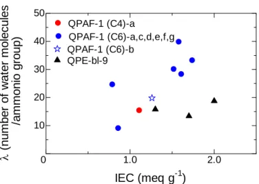
Figure 2-8 shows water uptake of QPE-bl-4 membranes as a function of the IEC. As expected, the higher IEC membranes showed higher water uptake. The higher IEC membrane also showed higher hydroxide ion conductivity. The hydroxide ion conductivity increased with λ, which is number of absorbed water molecules per ammonium group (Figure 2-9). These results imply that the absorbed water molecules contribute effectively to the hydroxide ion conduction. Figure 2-10 shows hydroxide ion conductivities of the QPE-bl-4 membranes as a function of reciprocal of the temperature. The conductivity of three QPE-bl-4 membranes showed approximate Arrhenius-type dependence up to 80 °C. The highest hydroxide conductivity was 45
mS cm-1 at 80 °C for the highest IEC membrane. The apparent activation energies were
estimated from the slopes to be 12.3 (1.3 meq g-1), 13.0 (0.9 meq g-1), and 15.4 (0.7
meq g-1) kJ mol-1, respectively. These values are in accordance with the reported values
for Tokuyama A901 membrane (14.1 kJ mol-1)10 and are similar with that of 1 M KOH
aqueous solution (9.37 kJ mol-1), indicating the hydroxide ion conduction involves
migration of hydrated hydroxide anions.11,12
Figure 2-8. Water uptake of QPE-bl-4 membranes.
0.6 0.8 1.0 1.2 1.4 0 10 20 30 40 50 IEC (meq g-1) Wa te r u p ta k e ( % )
- 30 -
Figure 2-10. Temperature dependence of hydroxide ion
conductivity of QPE-bl-4 membranes; ▲ (x16y12) IEC = 1.3 meq g-1, ■(x25y12) IEC =0.9 meq g-1, and ♦ (x16y6) IEC = 0.7 meq g-1.
2.8 3.0 3.2 3.4 10-2 10-1 1000/T (K-1) OH - Conduc ti v it y ( S c m -1 ) 80 70 60 50 40 30 Temperature (oC)
Figure 2-9. Hydroxide ion conductivity of QPE-bl-4 membranes as
a function of λ at 60 °C. 10 20 10 20 30 40 50 0
λ (number of water molecules/ammonio group)
OH - C onduc ti v it y at 60 o C ( m S cm -1 ) (x16y12) 1.3 meq g-1 (x25y12) 0.9 meq g-1 (x16y6) 0.7 meq g-1
- 31 -
Figure 2-11 shows TEM image of QPE-bl-4 (x16y12) (IEC = 1.3 meq g-1) stained
with tetrachloroplatinate ions. The dark areas represent ionic clusters composed of ammonium tetrachloroplatinate groups. The hydrophilic domains were ca. 4-8 nm wide and inter-connected and the hydrophobic domains were ca. 15-20 nm wide. The volumes of hydrophilic and hydrophobic block moieties were roughly estimated via
semi-empirical molecular orbital method to be 0.45 nm3 and 0.58 nm3, respectively.
Assuming that those domains were spherical, the radius for hydrophobic (x16) and hydrophilic (y12) sphere will be both 1.2 nm. The values are much smaller than the domain sizes observed in TEM images. The results indicate that the hydrophilic and hydrophobic aggregates were not perfect and only some part of the block segments were likely to participate in the phase separation. Such phase-separated morphology with ionic connections is considered to be responsible for high hydroxide ion conductivity of the QPE-bl-4 membranes.
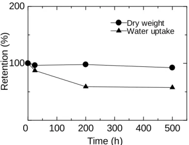
2.3.4 Stability of QPE-bl-4 membranes
The stability of QPE-bl-4 membranes was tested in alkaline solution. Figure 2-12 shows changes in weight (dry membrane) and water uptake of QPE-bl-4 membrane
(IEC = 1.3 meq g-1) as a function of soaking time in 1 M KOH aqueous solution
containing 5wt% hydrazine at 80 °C. The weight loss was very minor after 500 h testing. The membrane maintained its toughness and flexibility (Figure 2-13). As a comparison, our laboratory previous ammonium-containing poly(arylene ether) block copolymer membranes with no fluorine groups became brittle under the same conditions. The partially fluorinated polymer main chain structure would be
20 nm
Figure 2-11. TEM image of QPE-bl-4 (x16y12) membrane
- 32 -
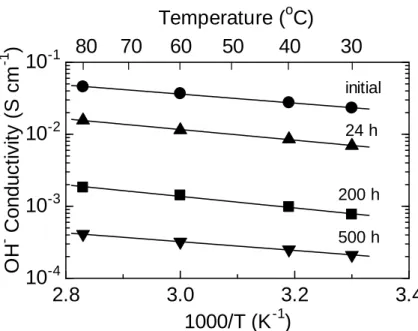
responsible for this good stability. Instead, the water uptake decreased to 42% after the test, indicating the loss of hydrophilic ammonium groups. In order to further investigate the decomposition of ammonium groups, hydroxide ion conductivity was compared with that of the pristine membrane (Figure 2-14). Similar to the water uptake, hydroxide ion conductivity decreased with testing time. The hydroxide ion conductivity at 60 °C decreased from 37 mS cm-1 (initial) to 0.41 mS cm-1 (after 500 h). The apparent activation energies for the hydroxide ion conduction were nearly
comparable, 12.0 (pristine), 14.1 (24 h), 15.3 (200 h), and 11.7 (500 h) kJ mol-1,
respectively. The results indicate that the loss of ammonium groups did not alter the anion conducting mechanism in the membranes.
Figure 2-12. Changes in weight and water uptake of QPE-bl-4
(x16y12) membrane (IEC = 1.3 meq g-1) during the stability test in
KOH/hydrazine aqueous solution at 80 °C.
100 200 300 400 500 100 200 0 Dry weight Water uptake Ret ent ion ( % ) Time (h)
- 33 -
Before the test After the test
Figure 2-13. Photographs of QPE-bl-4 (x25y12) membrane (IEC = 0.9
meq g-1) before and after the stability test in KOH/hydrazine aqueous
solution at 80 °C.
Figure 2-14. Changes in hydroxide ion conductivity of QPE-bl-4
(x16y12) membrane (IEC = 1.3 meq g-1) during the stability test in
KOH/hydrazine aqueous solution at 80 °C.
2.8
3.0
3.2
3.4
10
-410
-310
-210
-11000/T (K
-1)
OH
-Conduc
ti
v
it
y
(
S
c
m
-1)
80
70
60
50
40
30
Temperature (
oC)
initial 24 h 200 h 500 h- 34 - 2.4 Conclusions
For the synthesis of partially fluorinated poly(arylene ether) block copolymers containing ammonium groups, I first examined the effect of nitrile and fluorine groups on the chloromethylation reaction for the model oligomers 1 and 2. The chloromethylation of the oligomer 2 (with nitrile groups) caused decomposition, while that of the oligomer 1 (with fluorine groups) was successful to substitute selectively and quantitatively the chloromethyl groups on the fluorenyl groups without any detectable side reactions. From the precursor block copolymers containing oligomeric component of 2, novel ammonium-substituted block copolymers (QPE-bl-4) were synthesized via chloromethylation followed by quaternization reactions with trimethylamine. The QPE-bl-4 membranes showed water absorbability and hydroxide
ion conductivity. The highest conductivity in water at 80 °C was 45 mS cm-1 for the
membrane with IEC = 1.3 meq g-1. Such high conductivity is derived from
hydrophilic/hydrophobic phase-separated morphology with well-interconnected ionic channels as confirmed by TEM image of the stained membrane sample. The apparent activation energies for the hydroxide ion conduction were in the range of 12.3 - 15.4 kJ
mol-1, indicating transport mechanism involving hydrated hydroxide ions. The stability
of QPE-bl-4 was tested by soaking in KOH aqueous solution containing hydrazine at 80 °C. The weight loss was very minor after 500 h testing, however, the conductivity decreased to ca. 30% after 24 h. The results suggest that the ammonium groups were unstable while the polymer main chains were rather stable under the strong basic conditions.
References
1. C. G. Arges, V. Ramani, P. N. Pintauro, ECS Interface 2010, 19, 31-35.
2. G. Couture, A. Alaaeddine, F. Boschet, B. Ameduri, Prog. Polym. Sci. 2011, 36, 1521-1557.
3. M. Tanaka, M. Koike, K. Miyatake, M. Watanabe, Macromolecules 2010, 43, 2657-2659
4. M. Tanaka, M. Koike, K. Miyatake, M. Watanabe, Polym. Chem. 2011, 2, 99-106.
- 35 -
5. M. Tanaka, K. Fukasawa, E. Nishino, S. Yamaguchi, K. Yamada, H. Tanaka, B. Bae, K. Miyatake, M. Watanabe, J. Am. Chem. Soc. 2011, 133, 10646−10654. 6. W. Mei, Z. Wang, Chem. Res. Chin. Univ. 2015, 31, 1056-1061.
7. M. A. Hickner, H. Ghassemi, Y. S. Kim, B. R. Einsla, J. E. McGrath, Chem. Rev. 2004, 104, 4587-4612.
8. A. N. Lai, L. S. Wang, C. X. Lin, Y. Z. Zhuo, Q. G. Zhang, A. M. Zhu, Q. L. Liu, J. Membr. Sci. 2015, 481, 9-18.
9. K. Yamada, K. Yasuda, N. Fujiwara, Z. Siroma, H. Tanaka, Y. Miyazaki, T. Kobayashi, Electrochem. Commun. 2003, 5, 892-896.
10. J. Zhou, J. Guo, D. Chu, R. Chen, J. Power Source, 2012, 219, 272–279.
11. R. J. Gilliam, J. W. Graydon, D. W. Kirk, S. J. Thorpe, Int. J. Hydrogen Energy
2007, 32, 359-364
- 36 -
Chapter 3.
Effect of perfluoroalkyl groups in the anion conductive
polymer main chains on the alkaline stability and properties
3.1 Introduction
In the previous Chapter 2, I reported that QPE-bl-4 based on poly(arylene ether) was rather robust to maintain the self-supporting membrane in alkaline stability test due to the presence of fluorinated phenylene groups in replace of sulfone and ketone groups. However, as Kim et al. and Ramani et al. reported, the main chain degradation of quaternized poly(arylene ether)s was triggered by the attack of hydroxide ions at the
phenylene carbons ipso to the ether bonds.1-3 Taking these knowledges into account,
our idea for further improving alkaline stability is to eliminate those heteroatom linkages from the polymer main chains. More recently, our laboratory has developed advanced aromatic copolymer (QPE-bl-9) sharing the same hydrophobic component with QPE-bl-4 and containing ammonium-functionalized oligophenylene moieties as the hydrophilic component. The membrane exhibited high hydroxide ion conductivity
(138 mS cm-1 at 80 ºC in water) and reasonable alkaline stability due to large local IEC
value and lack of heteroatom linkages in the hydrophilic moieties. However,
insufficient elongation properties and insolubility of the membrane remain issues.4
In this chapter 3, I report advanced version of aromatic copolymer membranes (QPAF-1) composed of perfluoroalkylene chains as the hydrophobic component and the quaternized oligophenylene groups as the hydrophilic component and thus, no heteroatom linkages (such as ether, sulfone, and ketone groups) were included in the polymer main chains. The perfluoroalkylene chains were the same components as Nafion which is bench mark proton exchange membrane for fuel cells. The introduction of the highly hydrophobic perfluoroalkylene chains were expected to provide AEMs with improved ion conductivity, mechanical properties, and solvent solubility. Nafion is soluble in ethanol and exhibits high mechanical property and high
- 37 -
proton conductivity due to its unique morphology as a result of phase separation
between hydrophobic main chain and hydrophilic sulfonic groups.5 Their synthesis,
structure, properties (hydroxide ion conductivities, water uptake, gas permeability, and mechanical properties), alkaline stability, and hydrogen/oxygen fuel cell performance have been investigated in detail. Since QPAF-1 membranes contained the perfluoroalkylene groups in the main chain, their properties are compared to those of the perfluorinated sulfonic acid polymer, Nafion, membrane.
3.2 Experimental Materials
Perfluoro-1,6-diiodohexane (> 98%, TCI), perfluoro-1,4-diiodobutane (> 95%, TCI) 1-chloro-3-iodobenzene (> 97%, TCI), copper (Cu) powder (particle size 75-150 μm, > 99%, Kanto Chemical), dimethyl sulfoxide (DMSO) (> 99%, Kanto Chemical), 1,3-dichlorobenzene (> 98%, TCI), 1,4-dichlorobenzene (> 99%, TCI), 2,2’-bipyridine
(> 99%, TCI), bis(1,5-cyclooctadiene)nickel(0) (Ni(COD)2) (> 95%, Kanto Chemical),
N,N-dimethylacetamide (DMAc) (> 99%, Kanto Chemical), chloromethyl methyl
ether (CMME) (> 95%, TCI), zinc chloride (ZnCl2) (> 98% Kanto Chemical), thionyl
chloride (SOCl2) (> 98%, TCI), 1,1,2,2-tetrachloroethane (TCE) (> 98%, Kanto
Chemical), 45wt% trimethylamine aqueous solution (Aldrich) were used as received. Other chemicals were of commercially available grade and used as received.
Synthesis of perfluoroalkylene monomers
A 100 mL three-necked flask equipped with a nitrogen inlet was charged with perfluoro-1,6-diiodohexane (5.54 g, 10.0 mmol), 1-chloro-3-iodobenzene (11.9 g, 50.0 mmol), Cu powder (9.53 g, 150 mmol) and DMSO (60 mL). The mixture was heated at 120 °C for 48 h. After the reaction, the mixture was poured into 300 mL of 0.1 M nitric acid to precipitate a gray powder. The crude product was collected by filtration and dissolved in 300 mL of methanol. The solution was filtered with a PTFE membrane filter (0.45 μm pore size, omnipore). The gray solid was washed several times with methanol. Into the combined filtrate, 500 mL of deionized water was poured slowly to
- 38 -
precipitate a white crystalline powder. The product was washed with 1/1 (by volume) mixture of methanol and water several times and dried at 60 °C in a vacuum oven to obtain pure perfluoroalkylene monomer 1 (x = 6) in 85% yield. The shorter chain length perfluoroalkylene monomer 1 (x = 4) was prepared in a similar manner from perfluoro-1,4-diiodobutane (30% yield).
Polymerization
A typical procedure is as follows. A 100 mL three-necked flask equipped with a nitrogen inlet and a mechanical stirrer was charged with the monomer 1 (x = 6) (5.42 g,
10.4 mmol), 1,3-dichlorobenzene (0.73 g, 4.99 mmol), 1,4-dichlorobenzene(0.95 g,
6.44 mmol), 2,2’-bipyridine (8.52 g, 54.5 mmol) and DMAc (55 mL). The mixture was
heated at 80 °C to obtain a homogeneous solution. To this mixture, Ni(COD)2 (15.0 g,
54.5 mmol) was added. After the polymerization for 3 h, the mixture was poured into 300 mL of methanol to precipitate a black powder. The crude product was treated with concentrated hydrochloric acid overnight, washed with water and methanol several times, and dried at 60 °C in a vacuum oven to obtain a white powdery product (PAF-1 (C6)-b (m1.00n0.48o0.62)) in 82% yield.
Chloromethylation of PAF-1 (C6)-b
A typical procedure is as follows. A 100 mL round-bottomed flask equipped with a condenser was charged with PAF-1 (C6)-b (m1.00n0.48o0.62) (4.20 g) and TCE (43 mL). After dissolution of the polymer, CMME (87 mL, 125 equimolar to phenylene
unit in the hydrophilic moieties of the polymer), SOCl2 (13 mL, 20 equimolar to
phenylene unit in the hydrophilic moieties of the polymer), and ZnCl2 (1.18 g,
equimolar to phenylene unit in the hydrophilic moieties of the polymer) were added into the mixture. The mixture was heated at 80 °C for 24 h and poured into 800 mL of methanol to precipitate a white powder. The crude product was washed with methanol several times and dried at 60 °C in a vacuum oven to obtain a chloromethylated polymer (CMPAF-1 (C6)-b (m1.00n0.48o0.62)) in 97% yield.
- 39 - Quaternization of CMPAF-1(C6)-b
CMPAF-1 (C6)-b (m1.00n0.48o0.62) (2.00 g) was dissolved in 60 mL of 45 wt% trimethylamine aqueous solution. The mixture was stirred for 48 h at room temperature. Then, the mixture was poured into 240 mL of 2 M HCl to neutralize the excess trimethylamine. The mixture was dialyzed and evaporated to dryness to obtain a brown solid (QPAF-1 (C6)-b (m1.00n0.48o0.62)) in 98% yield.
Membrane preparation
QPAF-1 (C6)-b (2.00 g) was dissolved in 30 mL of DMSO. The solution was filtered with a syringe stuffed with cotton and cast onto a flat glass plate. Drying the solution at 80 °C overnight gave a transparent light brown membrane (ca. 50 μm thick).
Measurements
1H-NMR spectra were obtained on a JEOL JNM-ECA/ECX500 using deuterated
chloroform (CDCl3) or deuterated dimethyl sulfoxide (DMSO-d6) as a solvent and
0.03% tetramethylsilane (TMS) as an internal reference. Molecular weight was measured with GPC equipped with Shodex K-805L column and other systems were the same as in Chapter 2. TEM observation, hydroxide conductivity, water uptake were measured according to Chapter 2
Ion exchange capacity (IEC) was determined by titration. The membrane samples (ca.
50 mg) in chloride ion forms were immersed in 12.5 mL of 0.1 M NaNO3 for 24 h. The
amount of Cl- released from the membranes was measured by titration with 0.01 M
AgNO3 using K2CrO4 as an indicator and NaHCO3 as a pH adjuster. The ion
conductivity and water uptake of the membranes in chloride ion form were measured
under N2 with controlled humidity with a Bel Japan solid electrolyte analyzer system
MSB-AD-V-FC equipped with a chamber, a magnetic suspension balance, and a 4-probe conductivity cell. The chloride ion conductivities were measured after equilibrating for at least 1 h at set temperature and humidity by using an AC impedance spectroscopy (Solartron 1255B, Solartron Inc.). For water uptake
- 40 -
measurement, membrane samples were set in a chamber and dried at 80 °C under vacuum for 3 h to obtain dry weight, and the wet weight was collected after equilibrating for at least 1 h at set temperature and humidity.
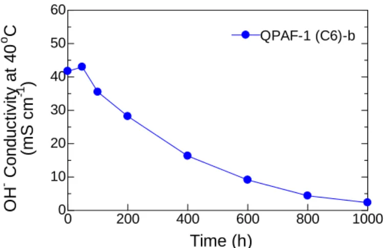
Alkaline stability test of the membranes was performed in 1 M KOH aqueous solution at 80 °C in PFA containers. The hydroxide ion conductivity was recorded in degassed water at 40 °C as a function of testing time. The post-test membranes were analyzed by IR spectra.
Gas permeability was measured using a GTR-Tech 20XFYC gas permeation measurement apparatus containing a Yanaco G2700T gas chromatography with a Porapak-Q column and a TCD detector. Argon and helium were used as a carrier gas for the measurement of hydrogen and oxygen, respectively. A membrane sample in chloride ion form (40 mm in diameter and 50 μm thick) was set in a cell that had a gas inlet and an outlet on both sides of the membrane. On one side of the membrane,
hydrogenor oxygen test gas was supplied at a flow rate of 30 mL min-1, while on the
other side of the membrane, the same gas as the carrier used in the gas chromatograph
(flow gas) was supplied at a flow rate of 20 mL min-1 and both side of gases were dried
or humidified under the same conditions to ensure homogeneous wetting of the membrane sample. Then, 7.4 mL of flow gas was sampled and subjected to the gas chromatography to quantify the test gas permeated through the membrane. The measurement was repeated until stable permeation data were obtained at least for 5 h.
Gas permeation coefficient, Q (cm3 (STD) cm cm-2 s-1 cmHg-1) was calculated by
following equations: Q = 273/T × 1/A × B × 1/t × 1/(76-PH2O), where T (K) is the
absolute temperature of the cell, A (cm2) is the permeation area, B (cm3) is the amount
of permeated test gas, t (s) is the sampling time, l (cm) is the thickness of the
membrane and PH2O (cmHg) is the water vapor pressure.
Dynamic mechanical analysis (DMA) was carried out with an ITK DVA-225 dynamic viscoelastic analyzer. Temperature dependence of storage modulus (E’(Pa)), loss modulus (E”(Pa)), and tan δ at 60% RH and 10 Hz was obtained for the
- 41 -
Tensile strength testing was carried out with a Shimadzu universal testing instrument Autograph AGS-J500N equipped with a temperature and humidity controllable chamber. The samples were cut into a dumbbell shape (35 × 6 mm (total) and 12 × 2 mm (test area)). Stress strain curves were obtained at 80 °C and 60% RH at a stretching rate of 10 mm min-1 after equilibrating the membrane at least for 3 h.
Preparation of catalyst coated membrane (CCM) and fuel cell operation
Pt (50 wt%) catalysts supported on carbon black (0.80 g) (TEC10E50E, Tanaka Kikinzoku Kogyo), water (3.30 g), and ethanol (3.30 g) were mixed by a planetary ball mill at 270 rpm for 30 min. After adding 5 wt% QPAF-1 (C6)-b solution in ethanol (6.80 g), the mixture was further mixed by a ball mill for 30 min at 270 rpm and by a pot mill for 12 h. The mass ratio of the dried ionomer and carbon black was adjusted to be 0.8. The slurry thus obtained was sprayed onto both sides of the QPAF-1 (C6)-b
membrane (54 μm thick) and pressed at 10 kgf cm-2 at r.t. for 3 min to obtain a catalyst
coated membrane (CCM). The coated area was 4.4 cm2. The Pt loading in the catalyst
layer was ca. 0.20 mg cm-2 for each electrode. The CCM was treated with 1.0 M KOH
for 48 h for ion exchange and with deionized water for 24 h to remove residual KOH. The treated CCM was mounted in a single cell with a gas diffusion layer and a gasket. Prior to the measurement, fully humidified hydrogen and nitrogen was supplied to the anode and cathode, respectively. The fuel cell was operated at 40 °C with supplying
full humidified H2 and O2 gas at a flow rate of 100 mL min-1 to the anode and the
cathode, respectively. The high-frequency resistance (HFR) of the cell was measured with a Kikusui FC impedance meter 2150 at 5.0 kHz.
3.3 Results and discussion
3.3.1 Synthesis of copolymers and membranes
The title quaternized copolymers were synthesized as shown in Scheme 3-1. Hydrophobic monomers 1 (x = 4, 6) were synthesized by the Ullmann coupling reaction of 1,4-diiodo-octafluorobutane or 1,6-diiodo-dodecafluorohexane and