Scan Tree Design : Test Compression with Test Vector Modification
9
0
0
全文
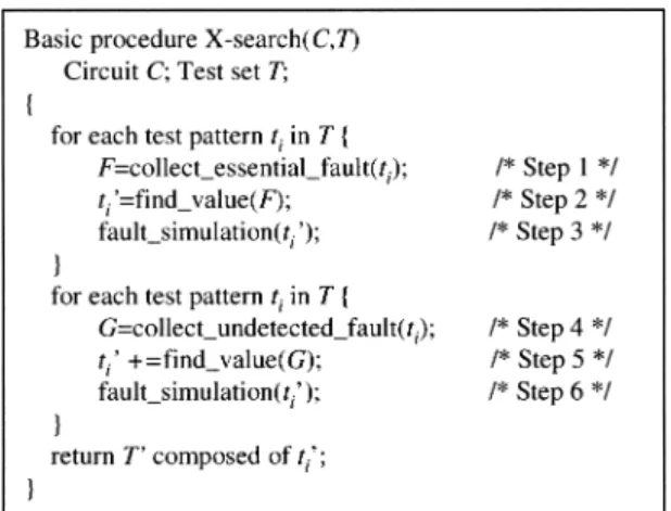
(2) Vol. 45. No. 5. Scan Tree Design: Test Compression with Test Vector Modification. ume and test application time on average by 70%. While a scan tree requires a single scan input, it requires more than one scan output. It requires long shift registers in a space compactor or a MISR to compress the output response. In this paper we also propose how to construct a scan tree where the number of outputs is limited. Experimental results with the limitation of the scan outputs show that the method could reduce test data volume and test application time on average by approximately 68%. At another aspect of the scan tree, we assume that scan flip-flops can be placed and routed as we want. It is known that requiring specific ordering of scan chains to realize scan tree may be costly and may impact the functional timing of the circuit 14),15) . For such situations we investigated a modified method that imposes some constraints on the manner the scan tree is designed. Experimental results show that the constrained scan tree could still achieve effective reduction of test data volume and test application time. This paper is organized as follows. In Section 2, techniques used in the proposed method are presented. In Section 3, the proposed method is explained. In Section 4, we propose how to limit the number of scan outputs. In Section 5, we give some experimental results for benchmark circuits, and give conclusions in Section 6. 2. Preliminaries 2.1 Scan Tree Figure 1 illustrates a single scan chain in which scan flip-flops are connected serially. The amount of test data for the scan chain is computed as the number of scan flip-flops times the number of test vectors. Hence in the case of Fig. 1 with the four test shown, the test data volume is 36 (= 9 ∗ 4) bits. We can observe that there exists scan flip-flops that receive the same logic values as some other scan flip-flops for every test vector. For example, scan flip-flops ff 3 , ff 4 and ff 6 receive the same logic values for every test vector. Such scan flip-flops are called “compatible” 16) . There are five groups of compatible scan flip-flops in Fig. 1, {ff 3 , ff 4 , ff 6 }, {ff 2 , ff 7 }, {ff 1 , ff 9 }, {ff 8 }, and {ff 5 }. As the ☆. This part has been published as a technical note in Miyase, K., Kajihara, S. and Reddy, S. M.: A Method of Static Test Compaction Based on Don’t Care Identification, IPSJ Journal, Vol.43, No.5, pp.1290–1293 (2002).. 1271. Fig. 1 Single scan chain.. Fig. 2 Scan tree.. compatible scan flip-flops can be driven by one scan input, the scan chain can be reconstructed into a scan tree given in Fig. 2. The root of the tree is the scan input and the leaves of the tree are the scan outputs. The concept of scan tree was introduced in Refs. 9), 10), 12) as a method of test compression for a full-scan circuit. The scan tree in Fig. 2 reduces the length of scan chain from 9 to 5, then the test data volume is reduced to 20 (= 5 ∗ 4) bits. Similarly, the test application time for each test vector is reduced from 9 clock cycles to 5 clock cycles. 2.2 Don’t-Care Identification Test vectors of a test set generated do not have unspecified values generally because they are specified by random fill or static/dynamic test compaction 17) for the detection of faults other than the target fault. However, some primary input values may be changed to opposite logic values without losing fault coverage. One can regard such input values as don’t cares (Xs). A method for identifying Xs of a generated test set without losing fault coverage has been proposed in Ref. 13). As the method utilizes fault simulation and procedures similar to implication and justification of ATPG algorithms, the computational time is practical enough. Figure 3 shows the basic procedure in.
(3) 1272. IPSJ Journal. May 2004. Fig. 3 Basic procedure for identifying X inputs.. Ref. 13). The method has two phases in terms of which faults to be targeted. At the first phase, it collects essential faults detected by each test vector. Note that an essential fault of a test vector is the fault detected by the test vector but not detected by any other test vectors in the test set. Then it finds logic values to guarantee that each test vector could detect the essential faults. For the logic values found, fault simulation is performed to drop faults. Then the method additionally specifies logic values to detect faults undetected. Finally unspecified values can be treated as Xs. In Ref. 13) it was reported that the approximately 50% of the input values are Xs even in compacted test sets for ISCAS benchmark circuits 2) . After a test set including Xs is obtained, arbitrary logic values can be assigned to the Xs. In this paper, we employ the procedure of don’t care identification in Ref. 13). To the Xs identified, we will assign logic values so as to minimize the height of a scan tree, to reduce test data volume and test application time. 3. Optimal Construction of A Scan Tree In this section we present the proposed method to determine an optimal scan tree for a given design with a single scan chain and a given test set. The method has three steps. In the first step maximal number of specified values in the test set are changed to Xs without reducing fault coverage. For this step we use the procedure in Ref. 13). Next we find a group of compatible flip-flops with minimum size, for the test set obtained in the first step, by solving an appropriate vertex coloring problem. Next we try to reduce the number of the groups of. Fig. 4 Test compaction and test compression.. compatible scan flip-flops by converting some of the specified values in the modified test set into the opposite values. This will help further reduce the number of groups of compatible scan flip-flops and hence the height of the scan tree. Finally we also iterate the last step to further reduce the height of the scan tree. 3.1 Overview of The Proposed Method When a test set is generated, the effects of test compression with a scan tree depend on the number of groups of compatible scan flip-flops. The smaller the number of groups of compatible scan flip-flops is, the lower the height of the scan tree is and the test data volume and test application time are reduced proportionately. Compatible scan flip-flops are determined from a given test set. If all values in the test set have been specified to either 0 or 1, there may not be many compatible scan flip-flops. In the proposed method, we first identify Xs in the given test set, and then we reassign appropriate logic values to the Xs so as to increase the number of compatible scan flip-flop groups. The procedure of reassigning logic values to Xs is similar to static compaction that is known as one of the test compaction techniques 17) . As shown in Fig. 4, static compaction aims at decreasing the number of test vectors by merging compatible tests. On the other hand, the procedure considered here aims at decreasing the number of groups of compatible scan flip-flops. We employ this procedure with some modifications. In this procedure, reassignment of values to Xs is done so that all scan flip-flops in.
(4) Vol. 45. No. 5. Scan Tree Design: Test Compression with Test Vector Modification. 1273. Table 1 Test set with Xs.. Fig. 6 A colored incompatibility graph.. Fig. 5 An incompatibility graph.. a group of compatible scan flip-flops have the same value. For this purpose an incompatibility graph is constructed and the problem of optimal reassignment of Xs is reduced to a vertex coloring problem for the graph. In the following subsections, we describe how to construct the incompatibility graph and discuss the vertex coloring problem. 3.2 Incompatibility Graph An incompatibility graph is a graph that represents relations of values applied to scan flipflops for every test vector. A vertex of the graph represents a scan flip-flop. An edge between two vertices exists if and only if two scan flip-flops corresponding to the vertices are incompatible. Table 1 shows some partially specified test vectors and Fig. 5 shows the incompatibility graph for those scan flip-flops. Scan flip-flop ff 1 and ff2 are incompatible because the second bits are different. Hence there is an edge between the vertices corresponding to ff 1 and ff 2 . On the other hand, scan flip-flops ff 2 and ff 3 are compatible. Hence there is no edge between vertices corresponding to ff 2 and ff 3 . 3.3 Vertex Coloring Problem For the incompatibility graph, we solve a vertex coloring problem, that is, we assign a color to each vertex of the graph such that any pair of adjacent vertices have different colors. As a color corresponds to a group of compatible scan flip-flops, the number of colors to be used must be minimized. From a solution of the coloring problem, we can find that scan flip-flop ff i represented by vertex vi can be compatible to other scan flip-flops whose vertex color is the. Fig. 7 An obtained scan tree.. same as of vi . For example in Fig. 6, color c1 is assigned to ff 1 , color c2 is assigned ff 2 and ff 5 , and color c3 is assigned ff 3 and ff 4 . There are some assignments of colors in general. While the vertex coloring problem is to find an assignment of the minimum number of colors, it is very time-consuming to find the optimum solution of the problem. In the proposed method, we solve the problem with a greedy algorithm, i.e., we assign colors to each vertex in order of edges incident on it. The colored incompatibility graph implies a structure of a scan tree. The vertices with the same color give groups of compatible scan flipflops. The compatible scan flip-flops are placed at the same level in the scan tree. Hence the number of colors used, which is the number of groups of compatible scan flip-flops, denotes the height of the scan tree. For example, since the graph in Fig. 6 has 3 colors, the number of compatible scan flip-flop groups is 3, {ff 1 }, {ff 2 , ff 5 }, and {ff 3 , ff 4 }. Thus the corresponding scan tree, shown in Fig. 7, has a height of 3. 3.4 Iteration of the Proposed Method and Don’t-Care Identification on Specific Bits After we obtain a modified test set by specifying the Xs so that all bits corresponding to a group of compatible scan flip-flops are the same, we can again apply the procedure of test modification by regarding the modified test set as a given test set. Because the combination of faults detected by each test vector would be.
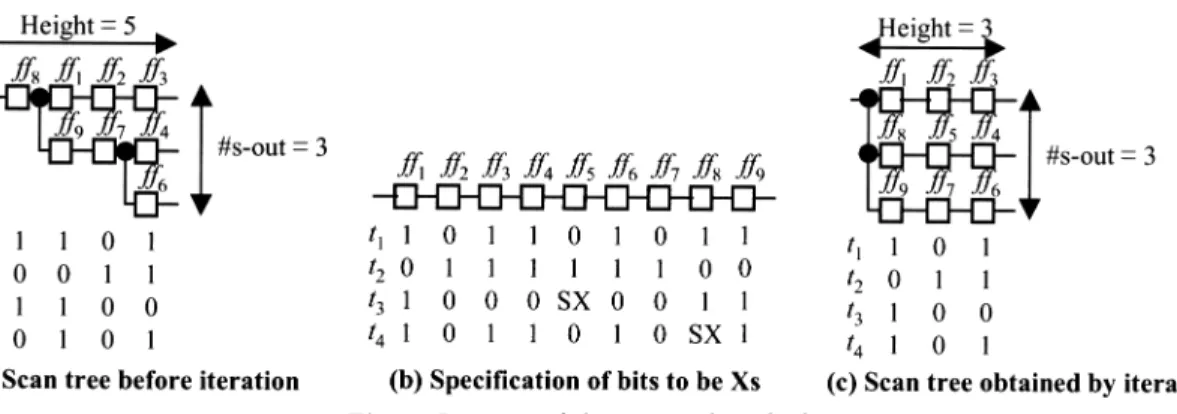
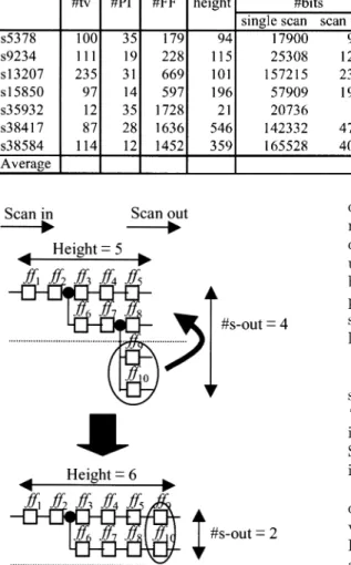
(5) 1274. IPSJ Journal. May 2004. Fig. 8 Iteration of the proposed method.. changed after modifying a test set, Xs are identified on different bit positions before and after modifying the test set. Thus the repetition may allow us to compress the test set furthermore. In the process of iterating the procedure, we try to decrease the number of groups of compatible scan flip-flops. If a scan flip-flop belongs to a large group of compatible scan flip-flops, values of such flip-flops should be left specified. On the other hand, if a scan flip-flop is not compatible with any other scan flip-flop, it is meaningful to change its values to Xs such that it will be compatible with some other flip-flop(s). Thus we need to selectively convert specified values to Xs. Such a procedure was given in Ref. 18), and we employ it in the process of iterating the procedure to reduce the height of the scan tree by reducing the number of groups of compatible scan flip-flops. Note that fault coverage of the original test set is still guaranteed in the iteration of the procedure because the procedures of Refs. 13) and 18) can identify Xs without losing fault coverage. We show an example using Fig. 8. Scan flipflop ff 5 in Fig. 8 (a) is not compatible with others. However, compared with logic values of ff 2 or ff 7 , the difference of logic values of ff 5 is only one bit, namely the third bit. Therefore, if the third bit of ff 5 can be changed to X without loss of fault coverage, the number of groups of compatible scan flip-flops is decreased. Similarly, the fourth bit of ff 8 is required to be an X, to join the compatible scan flip-flop group of to ff 9 and ff 1 . Thus, we can specify bits as shown in Fig. 8 (b) where “SX” shows a bit that we should attempt to change to X. If both bits discussed above are changed to Xs, the height of the scan tree is reduced to 3 as shown in Fig. 8 (c).. 4. Limitation of the number of scan outputs The scan tree often increases the number of scan outputs required. If the number of scan outputs is unlimited, the height of the scan tree is minimized, that is, test data volume and test application time can be minimized. However, the number of scan outputs is generally limited by the number of I/O pins, otherwise it requires long shift registers in a space compactor or a MISR to compress the output response. In order to avoid this problem, we limit the number of scan outputs for each scan tree to a predetermined number. The overhead of the space compactor or the MISR is reduced with a tradeoff to the increase of test data volume and test application time. Because the number of scan outputs of a scan tree is determined with the number of compatible flip-flops in the maximum group, we need to limit the number of flip-flops of each group. As a result, the height of scan tree is increased, that is, test data volume and test application time increase. When the number of scan flipflops in a group is more than the limited number of scan outputs, we remove some scan flip-flops in the group and build a new group for the removed flip-flops. An example is given in Fig. 9. Assuming that the limited number of scan outputs is 2, scan flip-flops ff 9 and ff 10 are moved to the leaves of the original scan tree. 5. Experimental Results We implemented the proposed method in C language on a PC (Dual Athlon MP 2000+, 512 MB), and applied it to ISCAS’89 benchmark circuits. The test sets used in this experiment were generated by a test generator that includes test compaction techniques 2) . Table 2.
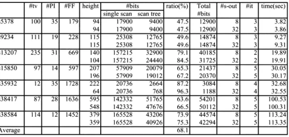
(6) Vol. 45. No. 5. Scan Tree Design: Test Compression with Test Vector Modification. 1275. Table 2 Experimental results for compacted test sets.. Fig. 9 Limitation of # scan outputs.. shows the results. The first four columns give the circuit name, the number of test vectors, the number of primary inputs and the number of scan flip-flops (pseudo primary inputs). The next column “height” shows the height of scan trees obtained by the proposed method. The next column “#bits” gives the test data volume in number of bits for the case of a single scan chain under “single scan” and for a single scan tree under “scan tree”. We can compute the number of bits required for the scan tree environment as the number of test vectors times the height of the scan tree. The next column “ratio(%)” gives the compression percentage of test data volume calculated by the following expression: Ratio(%) = (|Torg |−|Tcomp |)/|Torg | ∗ 100 where |Torg | is the total number of bits in the original test data under single scan environment and |Tcomp | is the total number of bits in the. compressed test data under scan tree environment. In this paper, although we focus on the compression for scan-in data volume, the column “Total #bits” gives test data volume for both primary inputs and scan inputs (pseudo primary inputs), that is, the test data volume stored in a tester. The test data volume calculated by the following expression: T otal#bits = (#P I + height) ∗ #tv The column “#s-out” gives the number of scan outputs of the scan tree. The columns “#it” shows the number of iterations when we iterate the proposed method as described in Section 3.4. The last column shows CPU time in seconds. As shown in Table 2, the proposed method could reduce approximately 70% of test data volume and test application time on average. For circuit s35932, the proposed method could achieve 98% of reduction. It can be seen that the more reduction in test data volume the proposed method achieves, the more number of scan outputs the scan tree requires. In Table 3, we show experimental results for uncompacted test sets. It can be seen that the percentage reduction of test data volume for the un-compacted test sets is higher than that for the compacted test sets. However the test data volume for the un-compacted test sets is higher than that for the compacted test sets for every circuit in terms of the number of bits. In order to measure the effectiveness of iteration of the procedure, we show results without iteration of the proposed method in Table 4. The columns “wo-it” and “w-it” show the results without iteration and with iteration, respectively. The proposed method with iteration could achieve higher compression than the method without iteration. In Table 5, we show the comparison of the proposed method with some previous works in terms of the number of bits required. For fair.
(7) 1276. IPSJ Journal. May 2004. Table 3 Experimental results for un-compacted test sets.. Table 4 Experimental results for compacted test sets with iteration.. Table 5 Comparison with previous works.. Table 6 Experimental results with limited numbers of scan outputs.. comparison we set the number of scan chains to 16 in the methods of Ref. 7) according to the method of Ref. 8). The values in Table 5. show the number of bits for primary inputs and scan inputs (pseudo primary inputs). The best result for each circuit is indicated in bold let-.
(8) Vol. 45. No. 5. Scan Tree Design: Test Compression with Test Vector Modification. 1277. Table 7 Experimental results with the constraint for compacted test sets.. Table 8 Experimental results with the constraint and 8 scan outputs.. Fig. 10 Constrained scan tree.. ters. For three circuits, the proposed method obtained the best results. While the methods of Refs. 6) and 7) need decompressors circuit, the proposed method doesn’t need a decompressor. In Table 6, we show the experimental results when we limit the number of scan outputs to 8, 32. The height of scan tree was increased from the unlimited case but we could achieve effective compression when the number of scan outputs is 32. The proposed method has some undesirable features in design as follows: ( 1 ) Routing overhead due to reordering scan flip-flops would increase. ( 2 ) Circuit delay would increase. For the case for which arbitrary scan trees may not feasible due to layout constraints, we made additional experiments. Though the place and route information depends on the circuit, we assume that the order of scan flip-flops in the scan chain is fixed and a scan flip-flop is allowed to be compatible with adjacent flipflops only. An example of a scan tree with this constraint is shown in Fig. 10. Table 7 shows results of the scan trees with this constraint.. The percentage reduction in test data volume given in Table 7 is smaller than the one in Table 2 for every circuit. However, the constrained scan trees still give effective results. For circuit s35932, the constrained scan tree could achieve 89% compression compared to 98% for the unconstrained case. The number of scan outputs required for the scan tree is at most 32 in Table 7. In Table 8, we limit the number of scan output as we keep the layout constraints. We set the number to 8. The scan tree still achieves 30% compression. 6. Conclusions In this paper we proposed a method of test compression for full-scan circuits. The proposed method constructed a scan tree based on a given test set. Since the height of the scan tree decides test data volume of the test set, the method modified the test set so as to minimize the height of the scan tree. In the procedure of test vector modification, an incompatibility graph was constructed and the problem of value assignment was reduced to a vertex coloring problem. To improve the effectiveness of test compression, the proposed method was iterated. Experimental results for ISCAS89 benchmark circuits show that the proposed method could reduce test data volume and test application time by 70% on average. Even in cases that we limited the number of scan outputs and that we added a hypothetical lay-.
(9) 1278. IPSJ Journal. out constraint, the proposed method could still achieve effective compression. References 1) Hamzaoglu, I. and Patel, J.H.: Test Set Compaction Algorithms for Combinational Circuits, ITC, pp.283–289 (1998). 2) Kajihara, S., Pomeranz, I., Kinoshita, K. and Reddy, S.M.: Cost-Effective Generation of Minimal Test Sets for Stuck-at Faults in Combinational Logic Circuits, IEEE Trans. CAD, Vol.14, No.12, pp.1496–1504 (1995). 3) Koenemann, B., et. al.: A Smart BIST Variant Guaranteed Encoding, 10th Asian Test Symposium, pp.325–330 (2001). 4) Barnhart, C., Brunkhorst, V., Distler, F., Fransworth, O., Keller, B. and Koenemann, B.: OPMISR: The Foundation for Compressed ATPG Vectors, ITC, pp.784–757 (2001). 5) Rajski, J., Tyszer, J., Kassab, M., Mukherjee, N., Thompson, R., Tsai, H., Hertwig, A., Tamarapalli, N., Murgalski, G., Eide, G. and Qian, J.: Emebedded deterministic test for low cost manufacturing test, ITC, pp.301–310 (2002). 6) Bayraktaroglu, I. and Orailoglu, A.: Test Volume and Application Time Reduction through Scan Chain Concealment, DAC, pp.151–155 (2001). 7) Reddy, S.M., Miyase, K., Kajihara, S. and Pomeranz, I.: On Test Data Volume Reduction for Multiple Scan Chain Designs, 20th IEEE VLSI Test Symposium, pp.103–108 (2002). 8) Hamzaoglu, I. and Patel, J.H.: Reducing Test Application Time for Full Scan Embedded Cores, Int’l Symposium on Fault-Tolerant Computing, pp.260–267 (1999). 9) Chang, S.-C., Lee, K.-J., Wu, Z.-Z. and Jone, W.-B.: Reducing test application time by scan flip-flops sharing, IEE Proc. Comput. Digit. Tech, Vol.147, No.1 (2000). 10) Sybille, S., Liang, H.-G. and Wunderlich, H.J.: A Mixed Mode Bist Scheme Based on Reseeding of Folding Counters, ITC, pp.778–784 (2000). 11) Lee, K.-J., Chen, J.-J. and Huang, C.-H.: Using a single input to support multiple scan chains, ICCAD, pp.74–78 (1998). 12) Rau, J.C., Jone, W.B., Chang, S.C. and Wu, Y.L.: Tree-structured LFSR synthesis scheme for pseudo-exhaustive testing of VLSI circuits, IEE Proc. Comput. Digit. Tech, Vol.147, No.5 (2000). 13) Kajihara, S. and Miyase, K.: On Identifying Don’t Care Inputs of Test Patterns for Combi-. May 2004. national Circuits, ICCAD, pp.364–369 (2001). 14) Makar, S.: A layout-based approach for ordering scan chain flip-flops, ITC, pp.341–347 (2000). 15) Pandey, A.R. and Patel, J.H.: Reconfiguration Technique for Reducing Test Time and Test Data Volume in Illinois Scan Architecture Based Designs, 20th IEEE VLSI Test Symposium, pp.9–15 (2002). 16) Chen, C.-A. and Gupta, S.K.: Efficient BIST TPG Design and Test Compaction via Input Reduction, IEEE Trans. CAD, Vol.17, No.8, pp.692–705 (1998). 17) Goel, P. and Rosales, B.C.: Test Generation and Dynamic Compaction of Tests, Digest of Papers 1979 Test Conf., pp.189–192 (1979). 18) Miyase, K., Kajihara, S., Pomeranz, I. and Reddy, S.M.: Don’t care identification on specific bits of test patterns, International Conference on Computer Design, pp.194–199 (2002).. (Received October 17, 2003) (Accepted March 5, 2004) Kohei Miyase received the B.E. and M.E. degrees from Kyushu Institute of Technology, in 2000 and 2002, respectively. Since 2002, he has been a Ph.D. student of Graduate School of Computer Science and Systems Engineering, Kyushu Institute of Technology. His research interests include reduction of SoC testing cost and Design for the Testability. He is a student member of the IEEE and the IEICE. Seiji Kajihara received the B.S. and M.S. degrees from Hiroshima University, Japan, and the Ph.D. degree from Osaka University, Japan, in 1987, 1989, and 1992, respectively. From 1992 to 1995, he was an Assistant Professor at Osaka University. In 1996, he joined the Department of Computer Science and Electronics of Kyushu Institute of Technology, Japan, where he is a Professor currently. His research interest includes test generation, delay testing, and design for testability. He received the Young Engineer Award from IEICE in 1997 and the Yamashita SIG Research Award from IPSJ in 2002. Dr. Kajihara is a member of the IEEE and the IEICE..
(10)
図


+4

関連したドキュメント
H ernández , Positive and free boundary solutions to singular nonlinear elliptic problems with absorption; An overview and open problems, in: Proceedings of the Variational
The only thing left to observe that (−) ∨ is a functor from the ordinary category of cartesian (respectively, cocartesian) fibrations to the ordinary category of cocartesian
We extend a technique for lower-bounding the mixing time of card-shuffling Markov chains, and use it to bound the mixing time of the Rudvalis Markov chain, as well as two
Keywords: Convex order ; Fréchet distribution ; Median ; Mittag-Leffler distribution ; Mittag- Leffler function ; Stable distribution ; Stochastic order.. AMS MSC 2010: Primary 60E05
The strategy to prove Proposition 3.4 is to apply Lemma 3.5 to the subspace X := (A p,2 ·v 0 ) ⊥ which is the orthogonal for the invariant form h·, ·i p,g of the cyclic space
Keywords: continuous time random walk, Brownian motion, collision time, skew Young tableaux, tandem queue.. AMS 2000 Subject Classification: Primary:
Kilbas; Conditions of the existence of a classical solution of a Cauchy type problem for the diffusion equation with the Riemann-Liouville partial derivative, Differential Equations,
Inside this class, we identify a new subclass of Liouvillian integrable systems, under suitable conditions such Liouvillian integrable systems can have at most one limit cycle, and
