A Neighbor-state Based Congestion Control Scheme for Adaptive Bandwidth Sharing
12
0
0
全文
(2) Vol. 41. No. 2. A Neighbor-state Based Congestion Control Scheme. mize the traffic of control packets. NBQ informs their link state to the upstream router only when the output link is congested and there is a buffer overflow causing packets to be dropped. • To avoid complicated packet forwarding in routers, NBQ employs FIFO queuing, and controls only the non-adaptive flows. This paper takes a fundamental approach to effective bandwidth sharing by resolving mismatched allocation and wasted allocation, which has not been addressed in previous work. The remainder of the paper is organized as follows. Section 2 of the paper discusses current queuing models based on our simulations. Section 3 observes the problem of queue build up under various scenarios. In Sections 4 and 5, we propose our scheme and its implementation. Section 6 compares NBQ with other queuing models. Section 7 describes related work. Sections 8 and 9 include discussion and future work, followed by a conclusion. 2. Performance Analysis of Current Queuing Models In this section, we evaluate current queuing models by simulation. All simulations were performed using ns-2 11) . It is known to provide accurate packet-level implementation for various network protocols, buffer management, and scheduling algorithms. 2.1 Simulation Environment We consider a single 10-Mbps congested link shared by N flows, and performed experiments based on the topology shown in Fig. 1. To examine the link sharing performance, we use four different queuing models, First In First Out (FIFO), Random Early Detection (RED) 5) , Fair Random Early Drop (FRED) 9) , and Deficit Round Robin (DRR) 17) , described below. • FIFO: Today’s routers almost adopt FIFO queuing as a buffer management, in which packets are served in a first-in first-out order. The buffers are managed using a simple drop-tail strategy when the buffer is full. FIFO discards a packet without regard to which flows the packet belongs to or how important the packet is. • RED and FRED: RED serves packets in a first-in first-out order, but this buffer management is significantly more sophisticated than drop-tail. RED maintains two buffer thresholds, and drops incoming. 211. 10Mbps, 1ms Node1 Fig. 1. N flows. Node2. Simulation environment.. packets with dynamically calculating ratio when the average number of queued packets exceeds the first threshold. Whenever it exceeds the second threshold, all arrival packets are dropped. FRED, a modified version of RED, provides some degree of fair bandwidth allocation. FRED uses peractive-flow accounting to impose on each flow a loss rate that depends on the flow’s buffer use. We use the FRED ns-2 implementation which was published by Ion Stoica of CMU 18) . FRED preferentially drops a packet of a flow that has either had many packets dropped in the past (FRED-1), or a queue larger than the average queue size (FRED-2). FRED-2 guarantees each flow a minimum number of buffers, and performs better than FRED-1 only when the number of flow is large. • DRR: DRR achieves an efficient O(1) substitute for the O(log(n)) sorting bottleneck in WFQ. DRR associates each flow with a deficit counter initialized to zero. Packets coming in on different flows are stored in different queues. DRR scheduler visits each queue in turn and serves one quantum. Each queue is allowed to send out packets in the first round subject if it is no larger than the quantum. If it is larger, the quantum is added to the flow’s deficit counter. If the scheduler visits a queue where the total of the flow’s deficit counter and the quantum is larger than or equal to the size of the front packet, the front packet is served, and the deficit counter is reduced by the packet size. From Node1 to Node2, five flows are transmitted. Four simulations are cases when there are 1) five TCP flows, 2) one TCP flow and four UDP flows, 3) one UDP flow and four TCP flows, and 4) five UDP flows sharing a single congested link. The different queuing models tested for each simulation are FIFO, RED, FRED, and DRR. Unless otherwise specified, we use the following parameters for the simulations in the section. Each link has a bandwidth of 10 Mbps, a delay of 1 ms, and a buffer of 32 KB. In the.
(3) 212. Transactions of Information Processing Society of Japan. . «§ «§. «§ «§. . «§. . Fig. 2. ¦. ©. ©. ©. The throughput of five TCP flows sharing a 10-Mbps link.. . «§ «§. «§ ¬§. Fig. 4. ¦. . ©. ©. ©©. ¬§¤¹ÇÊ. ¬§¤¹ÇÊ. ¬§¤¹ÇÊ. ¬§¤¹ÇÊ. ¬§¤¹ÇÊ. . . ©. The throughput of one TCP flow, and of four UDP flows sending at 10-Mbps CBR.. . «§. «¿ÉÆ̾¿ÇÌˤ¹ÇÊ. «¿ÉÆ̾¿ÇÌˤ¹ÇÊ. ¬§. . . ©©. . . . Fig. 3. ¬§ ¬§. . . . «§ ¬§. . «¿ÉÆ̾¿ÇÌˤ¹ÇÊ. «¿ÉÆ̾¿ÇÌˤ¹ÇÊ. . Feb. 2000. ¦. ©. ©. ©. ©©. The throughput of one UDP flow sending at 10-Mbps CBR, and of four TCP flows sharing a 10-Mbps link.. RED and FRED cases, the first threshold is set to 8 KB, while the second one is set to 16 KB. The DRR quantum size is set to 1000 bytes. We use File Transfer Protocol (FTP) with TCP and Constant Bit Rate (CBR) with UDP as flows generating applications. The TCP implementation is a BSD compatible two-way TCP based on TCP-Reno. The packet payload size is 1000 bytes. Delayed ACK is enabled. 2.2 Some Flows Share a Single Congested Link Figure 2 shows the throughput of five TCP flows sharing a 10-Mbps link. In this case when all flows perform identical flow control algorithm and queuing model, even incomplex FIFO queuing can allocate almost a fair bandwidth share rate to each flow. Unfortunately, in current Internet environment, since a variety of flow control algorithms run over IP, we should not design a flow control mechanism assuming this case. Figure 3 shows the throughput of one UDP flow sending at 10-Mbps CBR, and of four TCP flows sharing a 10-Mbps link. In FIFO and RED, the UDP flow almost fully occupied the link bandwidth. Since these two. Fig. 5. ¦. ©. ©. ©. ©©. The throughput of five UDP flows. The CBR for Flow i is i times larger than its fair share.. queuing models do not classify the arrival flows, a non-adaptive UDP flow suppresses adaptive TCP flows. On the other hand, FRED and DRR are able to allocate fair bandwidth share rate to all flows. To avoid one specific flow occupying a router’s buffer, FRED limits the number of packets to a maximum allowed per-flow queue size. Since the limitation is not worth a fair rate, FRED does not completely achieve fair bandwidth sharing. Figure 4 shows the throughput of one TCP flow, and of four UDP flows sending at 10-Mbps CBR. In FIFO and RED, UDP flows almost fully occupied the link bandwidth. In FRED, TCP congestion control was invoked frequently, and only the rest of the usage of UDP flows is allocated. Only DRR achieves high fair bandwidth sharing performance. Figure 5 shows the throughput of five UDP flows. The CBR for flow i is i times larger than its fair bandwidth share. The rates of the five UDP flows are 2 Mbps, 4 Mbps, 6 Mbps, 8 Mbps, and 10 Mbps. In this simulation, although FRED achieves a good sharing performance, DRR achieves the nearest to the complete fair sharing performance..
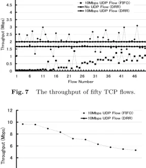
(4) Vol. 41. No. 2. A Neighbor-state Based Congestion Control Scheme. 2.3 Discussion on the Simulation Results From the observations of the simulation for a single congested link, FIFO and RED cannot support fair bandwidth sharing for different flow control mechanisms. Fair bandwidth sharing performance is possible with FRED and DRR. Unlike other mechanisms, DRR achieves a high level fair bandwidth sharing. To actualize a fair bandwidth sharing mechanism, there is a need to implement a type of technique in the router to maintain the flow status. As in DRR, complicated scheduling and multiple buffer queues can make fair bandwidth sharing possible, but there is an increase of delay at the router that becomes a problem. In the case of FRED, the delay at the router is small compared to DRR because FRED has only one buffer queue, and uses FIFO. Seeing the results from all the simulations, the flows bandwidth usage is different based on what type of queuing model is used. On the other hand, if we total the throughput of all flows that share a bandwidth, we can see that the links are occupying most of the available 10-Mbps bandwidth. 3. Issues in Current Queuing Models In the previous section, we analyzed the performance of multiple adaptive and non-adaptive flows, that share a single congested link. We used various current queuing models in the analysis. As a result, the 10-Mbps bandwidth in a single link is fully utilized and capable of achieving an effective usage of bandwidth. However, when a flow is transmitted through multiple links there is no guarantee that the allocated bandwidth of one link will be allocated again for the next links. 3.1 Simulation Environment We conducted a simulation on a wide area network environment shown on Fig. 6. The CBR flow between UDP Source-1 and UDP Sink-1 is transmitted through eleven routers. From G1 to G10 , there are five TCP source nodes connected. From G2 to G11 , there are five TCP sink nodes connected. The TCP source connected to GN communicates with the TCP sink connected to GN +1 . As a total, there are fifty TCP connections. We set the bandwidth of each link to 10 Mbps, the delay to 1 ms, and the queue buffer to 32 KB. The CBR of the 1000-byte UDP packet was set to 10 Mbps. A thirty second simulation was conducted five. TCP Source 1. 2. 3. 4. TCP Source 5. 6. 10. L1 G1. L2 G2. 213 TCP Source 46 47 48 49 50. L9. L10 G10. G11. UDP Source. UDP Sink. TCP Sink. Fig. 6. TCP Sink. TCP Sink. Simulated network topology.. times, and the average was taken as its performance measurement. For the routers queuing model, we used FIFO and DRR referred in the previous section for its high and fair bandwidth sharing performance. 3.2 The Flow Dynamic through Multiple Links In the previous section, we used several queuing models to simulate a single congested link. In this section, we conducted a simulation on an environment that has multiple links as shown in Fig. 6. We conducted two simulations with two queuing models, FIFO and DRR. We tested two cases: with and without the UDP flow. Figures 7 and 8 show the throughput of fifty TCP flows and the UDP throughput of each link from L1 to L10, respectively. One can observe that the throughput of fifty TCP flows is degraded by the UDP flow. Unlike the adaptive TCP, the UDP flow is non-adaptive, which results in abusing the bandwidth. Such a problem can be solved using fair queuing schemes like DRR, which enables fair bandwidth sharing performance. As seen, a fair bandwidth share rate is allocated to each flow in the link. However, in an actual wide area Internet environment, it is close to impossible for the flow to pass all the routers that contain the same bandwidth and always allocate the same fair bandwidth share rate. It can be difficult for all the routers to adopt the same queuing model like DRR. 3.3 The Dynamics of the Flow through Bottleneck Link In a wide area network where multiple flows exist, routers and links may suffer from congestion, or the bandwidth may be narrow and unavailable. For example, the links that transmit the flows from service providing servers like Video-On-Demand are easily saturated. In such a case, that link becomes a bottleneck in the transmission..
(5) 214. Transactions of Information Processing Society of Japan ¥Æ ¬§ ÃÆÎ ¦ ¤¹ÇÊ ¬§ ÃÆÎ ¦. . ¤¹ÇÊ ¬§ ÃÆÎ ©©. ¥Æ ¬§ ÃÆÎ ©©. «¿ÉÆ̾¿ÇÌËw¤¹ÇÊ. «¿ÉÆ̾¿ÇÌËw¤¹ÇÊ. . . . Fig. 7. . . . . . The throughput of fifty TCP flows.. . ÆËËüżºÂw£ÀÅÂ. . . . . ÃÆÎw¥ÌĹ¼É. . . . The throughput of fifty TCP flows, with a 1-Mbps bottleneck link.. . ¤¹ÇÊ ¬§ ÃÆÎ ¦ ¤¹ÇÊ ¬§ ÃÆÎ ©©. . «¿ÉÆ̾¿ÇÌËw¤¹ÇÊ. . Fig. 8. ¤¹ÇÊ ¬§ ÃÆÎ ©©. Fig. 9. ¤¹ÇÊ ¬§ ÃÆÎ ©©. . . ¤¹ÇÊ ¬§ ÃÆÎ ¦. ¤¹ÇÊ ¬§ ÃÆÎ ¦. . «¿ÉÆ̾¿ÇÌËw¤¹ÇÊ. ÃÆÎw¥ÌĹ¼É. . Feb. 2000. . ÆËËüżºÂw£ÀÅÂ. £. £. £. £. £ £ £ £ÀÅÂw¥ÌĹ¼É. £. £. £. The throughput of the UDP flow for each link.. . £. Fig. 10. The target of the current queuing model is to achieve its policy for a single link. On the other hand, the policy can change with the status of link traffic. If a router knew that the packets were going to be discarded, it would have been discarded at an upstream router. On designing a flow control mechanism, it is important to consider such a situation and conduct a suitable queuing process. We conducted another simulation using the same network topology shown in Fig. 6, setting L5 to a narrower bandwidth of 1 Mbps. Figure 9 shows the throughput of fifty TCP flows and Fig. 10 shows the UDP throughput for each link. In the case when all routers employ FIFO queuing, the throughput of the UDP flow shows a sudden decrease in the narrow bandwidth of L5 where the bottleneck occurs. The throughput of the TCP flows that used links prior to L5 showed a degrade in their performance due to the effect from UDP, while the TCP throughput using the links after L5 showed an increase in the available bandwidth due to the decrease in UDP flow rate. It can be seen that the 10-Mbps CBR had 9 Mbps when passing L4, but was decreased to 1 Mbps at L5. This means that 8 Mbps were wasted in L4. This 8 Mbps of wasted traffic. £. £. £. £ £ £ £ÀÅÂw¥ÌĹ¼É. £. £. £. The throughput of the UDP flow for each link, with a 1-Mbps bottleneck link.. causes a degrade in the TCP flow performance sharing the same link. In the case when all routers employ DRR queuing, the same results can be seen here. DRR applies a fair bandwidth sharing of 1.7 Mbps to the UDP flow prior to L5 while the UDP flow is limited to 0.2 Mbps in L5. Unfortunately, since it is restricted to 0.2 Mbps, as a result, it would mean that 1.5 Mbps were wasted. If this bandwidth is divided among five TCP flows, it would mean that 0.3 Mbps of high throughput will be possible for TCP bandwidth in L5 prior links as in links after L5. 3.4 Discussion on the Simulation Results From the above observations, we can see that wasted traffic occurs in non-adaptive flows in the following situations: when the flow passes links with different bandwidth, when the flow passes congested links, and when the flow passes routers with a different policy. Such situations are frequent cases in wide area networks at present. This can be seen in the case when a non-adaptive flow passing multiple FIFO routers comes to a DRR router with a congested link, and suffers from packet dis-.
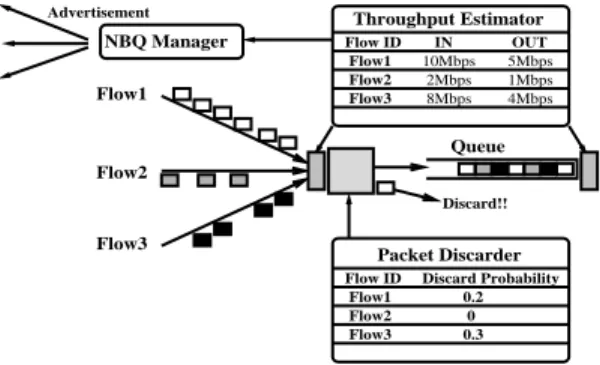
(6) Vol. 41. No. 2. A Neighbor-state Based Congestion Control Scheme. carding at the router. As a result, prior link bandwidth occupying discarded packets were wasted. With the present queuing model, fair bandwidth sharing for a single link, and an increase in QoS with careful tuning are possible, but when it involves the entire flow to pass multiple links, it can result in dividing a bandwidth that may become useless. For this reason, it is difficult to say that the routers are processing flows in the most suitable way. 4. Neighbor-state Based Queuing In this section, we present a new scheduling model, called Neighbor-state Based Queuing (NBQ), which improves the link sharing performance of the flows. Our goal is to reduce the wasted non-adapted flows and provides available bandwidth for the adaptive flows such as TCP. To avoid per-flow buffering and sophisticated scheduling, we use single FIFO queuing that rationally drop packets on input. NBQ only maintains the per-flow state of nonadaptive flows. Figure 11 shows NBQ architecture which consists of three principal modules. 1) NBQ Manager (NM) informs the next upstream router of per-flow information. 2) Throughput Estimator (TE) calculates the flow arrival and departure rates. 3) Packet Discarder (PD) discards an arrival packet on input. NBQ achieves a flow control by changing packet discard ratio of each flow. TE calculates an amount of per-flow arrival packets and departure packets, depending of packet classification with the protocol field and the destination address field in the IP header. In the case, when the protocol field of the arrival packet indicates TCP, TE immediately enqueues it to the buffer queue. TE maintains only the states of non-adaptive flow. In NBQ, the throughput estimation is done at both arrival and departure at regular intervals. These input and output rates of per-flow are notified to neighboring routers by NM, and these routers estimate the dropping packet ratios on this router. PD discards a packet at this ratio before enqueuing. 4.1 Packet Discard Ratio Estimation We now present an algorithm of estimating ˆout be the the packet discard ratio. Let a ˆin and a arrival and departure rate of flow i on router A. A, which is the packet dropping ratio of router A for flow i, should be calculated by Eq. (1).. Advertisement. Throughput Estimator. NBQ Manager Flow1. 215. Flow ID Flow1 Flow2 Flow3. IN 10Mbps 2Mbps 8Mbps. OUT 5Mbps 1Mbps 4Mbps. Queue Flow2 Discard!!. Flow3. Packet Discarder Flow ID Flow1 Flow2 Flow3. Fig. 11. Discard Probability 0.2 0 0.3. The NBQ architecture.. Also let Bold denote the previous packet discard ratio of router B for flow i. In the case where router B forwards flow i to router A at the dropping ratio of Bold , B, which is the required discard ratio of router B for flow i, should be given by Eq. (2). A smoothed value of Bold , Bnew , is given by Eq. (3), where β is a smoothing factor with a recommended value of 0.8, which is used to prevent the packet discard ratio from suddenly increase or decrease, in cases where the neighboring router is under temporary congestion. In addition, we need to consider the change in the packet arrival rate. Let ˆbin.new and ˆbin.old be the present and previous arrival rate. Since the packet discard ratio should depend on the change of arrival rate, Bnew is modified to Bdiscard given by Eq. (4). In addition, there is an average out function that calculates the average packet discard ratio of the flows sent to the identical downstream routers. This average becomes the actual packet discard ratio. This is done to keep fairness of each flow process in NBQ. This is different from DRR and FRED, which allocates fair bandwidth to each flow. a ˆout (1) A=1− a ˆin (2) B = 1 − (1 − A) × (1 − Bold ) Bnew = (β × Bold ) + ((1 − β) × B ) (3) ˆbin.new (4) Bdiscard = Bnew × ˆbin.old 5. Implementation In this section, we present the implementation of NBQ. Pseudocode for NBQ is shown in Figs. 12 and 13. EST INTERVAL is the regular measure of the interval for the packet arrival and depar-.
(7) 216. Transactions of Information Processing Society of Japan. Constants: MAX_DISCARD = 0.9 // Maxmum packet discard ratio MIN_DISCARD = 0.1 // Minimum packet discard ratio DECR_DISCARD = 0.6 // Decrease rate of packet discard ratio applied when the bandwidth becomes available EST_INTERVAL = 0.1 // Calculates the regular measuring interval of the packet arrival rate and departure rate WEIGHT = 0.8 // Weight of previous packet discard ratio ALLOW_IDLE = 2.0 // The amount of time per-flow variables are kept once the flow stops Global Variables: now nactive. // Current real time // The number of current active flow. Per-Flow Variables: in_bytei in_timei in_thi prev_in_thi out_bytei out_timei out_thi discard_ratioi qleni idle_timei presenti. // // // // // // // // // // //. Enqueuing module: if((idle_timei != 0) && ((now - idle_timei ) >= ALLOW_IDLE)) reset per-flow variables; else idle_timei = now; [Throughput Estimator module]; if(P_type == TCP) // Check a protocol type of packet (P_type) discard = 0; else discard = [Average_out module]; drop packet P with ratio discard; ++qleni ; Average_out module:. Total byte of arrival packets Estimated time of packet arrival rate Packet arrival rate Previous packet arrival rate Total byte of departure packets Estimated time of packet departure rate Packet departure rate Packet discard ratio Number of packets buffered Time when the packets stop arriving flag showing the flow’s presence. Per-Flow Variables from NBQ Manager: neighbor_in_thi // Packet arrival rate in downstream router neighbor_out_thi // Packet departure rate in downstream router. Fig. 12. Feb. 2000. Constants and variables for NBQ.. ture rate. We set this value to 100 ms. Unless we use long-delay links like a satellite network, the current network link delay is less than 100 ms. Satellite networks do not perform well with NBQ since it cannot reflect the neighboring link status correctly, due to its long link delay. As EST INTERVAL becomes smaller, NBQ becomes more sensitive to network traffic changes. The constant WEIGHT is used to balance the overload with a previous value to prevent the packet discard ratio from sudden increase or decrease, in cases where the neighboring router is under temporary congestion. DECR DISCARD is decided on the rate at which the packet discard ratio will decrease when the rate of the neighboring routers overload decreases. ALLOW IDLE decides on how many seconds the per-flow variables are held when NBQ stops receiving a flow. Unless the per-flow variables are not reset, it will use the old packet discard ratio. In this particular implementation, we set WEIGHT to 0.8, DECR DISCARD to 0.6, and ALLOW IDLE to 2.0 seconds. Additionally, to avoid the packet discard ratio from becoming 1 and leading to a flow halt, we arranged the maximum packet discard ratio MAX DISCARD value to less than 1 to control it. When the packet discard ratio in the flow of the neighboring router reaches a fixed value MIN DISCARD close to 0, the flow’s packet. total = 0; for(n = 1; n <= nactive; n++) total += discad_ration ; return total / nactive; Dequeuing module:. --qleni ; if(qleni == 0) { idle_timei = now; presenti = 0; } [Throughput Estimator module] Throughput Estimator module:. if(called from Enqueuing module) { in_bytei += P_size; // Add packet soze (P_size) if(now - in_timei >= EST_INTERVAL) { in_thi = in_bytei / (now - in_timei ); in_timei = now; in_bytei = 0; discard_ratioi = [Packet Discarder module]; prev_in_thi = in_thi ; } } else if (called from Dequeuing module) { out_bytei += P_size; if(now - out_timei >= EST_INTERVAL) { out_thi = out_bytei / (now - out_timei ); out_timei = now; out_bytei = 0; discard_ratioi = [Packet Discarder module]; } } Packet Discarder module:. neighbor_loss_rate = 1.0 - (neighbor_out_thi ) / (neighbor_in_thi ); // Eq.(1) loss_rate = max(0, neighbor_loss_rate); if(loss_rate <= MIN_DISCARD) return (discard_ratioi * DECR_DISCARD); discard_rate = 1.0 ((1.0 - loss_rate) * (1.0 - [Average_out module])); // Eq.(2) weighted_discard_rate = (WEIGHT * [Average_out module]) + ((1.0 - WEIGHT) * discard_rate); // Eq.(3) if(prev_in_thi == 0) input_change_rate = 1; else input_change_rate = in_thi / prev_in_thi ; // Eq.(4) return (weighted_discard_rate * input_change_rate);. Fig. 13. Pseudocode for neighbor-state based queuing.. discard ratio is decreased. The new value is set to the product of current packet discard ratio and DEC DISCARD. Eleven per-flow variables maintained in NBQ are updated differently. in byte and in prev are updated every time there is a packet input. out byte and out prev are updated every time there is a packet output. discard prob, in time, in th, out time, and out th, are updated with the EST INTERVAL cycle. 6. Evaluation In this section we use simulations, performed. i.
(8) Vol. 41. No. 2. A Neighbor-state Based Congestion Control Scheme. UDP Flow1. ¬§ «§. . ¬§ «§. «§ «§. «§. L1. Node1. . L4. L3. Node3. Node4. Node5. L2. Node2. Fig. 14. «¿ÉÆ̾¿ÇÌˤ¹ÇÊ. Bottleneck Link. UDP Flow2. . Simulation network topology.. . ¬§ «§. . ¬§ «§. «§ «§. £. £. £. £. £ÀÅÂw¥ÌĹ¼É. «§. Fig. 16. . The throughput of the flows for each link using DRR.. . £. £. £. £. £ÀÅÂw¥ÌĹ¼É. Fig. 15. ¬§ «§. «§ «§. «§. . . ¬§ «§. . The throughput of the flows for each link using FIFO.. «¿ÉÆ̾¿ÇÌˤ¹ÇÊ. «¿ÉÆ̾¿ÇÌˤ¹ÇÊ. 217. . £. £. £. £. £ÀÅÂw¥ÌĹ¼É. Fig. 17. . «¿ÉÆ̾¿ÇÌˤ¹ÇÊ. using the ns simulator. To evaluate the performance of the NBQ, we simulated our scheme and measured the reduction of wasted nonadaptive flows. We also estimated how the reduction of traffic benefits the adaptive flows. 6.1 Basic NBQ Performance We use the network configuration shown in Fig. 14 to simulate the NBQ. We set the L4 bandwidth to 1 Mbps, and its delay to 1 ms such that L4 becomes the bottleneck link, while other links have 10-Mbps bandwidth and 1-ms delay. Two UDP flows of 10-Mbps CBR from Node1 and Node2 are transmitted to Node5. L3 is shared by five TCP flows. We compared NBQ, DRR, and FIFO by applying each mechanism to both Nodes 3 and 4. Figure 15 is the throughput of each flow using FIFO in Node3 and Node4. L1 and L2 contain one UDP flow each, and 10-Mbps bandwidth of the links is fully utilized by UDP-1 and UDP-2 flows. In L3, two adaptive UDP flows collide with one another and each flow is decreased to about half its size in the bandwidth. Moreover, the five adaptive TCP flows sharing L3 show an unfortunate degrade in its performance due to the UDP flows’ occupying most of the bandwidth. Since L4 has only 1Mbps, the bandwidth of UDP flow is limited approximately to 0.5 Mbps. Figures 16 and 17 show the results from the same experiment using DRR and NBQ. Un-. The throughput of the flows for each link using DBQ. ¥¨. ©©. ¦. . Fig. 18. ¬§ ¬§ «§ «§ «§ «§ «§. The comparison of the each flow’s throughput between DBQ, DRR, and FIFO.. like the result from the experiment using FIFO, the bandwidth is allocated to the TCP flows in both queuing models. However, there is a large difference in how the two allocate bandwidth. DRR fairly divides the L3 bandwidth among seven flows, while NBQ reflects the advertise from Node4, and limits UDP from fully occupying the bandwidth with wastes. Figure 18 is the end host’s throughput of all the flows that compares FIFO, DRR, and NBQ. By using NBQ in routers between congested links, this simulation shows that NBQ achieves a more efficient usage of bandwidth compared to FIFO. It can be seen that the TCP flow performance has improved approximately.
(9) 218. Transactions of Information Processing Society of Japan 10. UDP Flow1 UDP Flow2. 9. 9. 8. 8. 7. 7. Throughput(Mbps). Throughput(Mbps). 10. Feb. 2000. 6 5 4 3. UDP Flow1 UDP Flow2. 6 5 4 3. UDP Flow2 Stops!! 2. 2. UDP Flow2 Stops!! 1. 1. 0. 0 5. Fig. 19. 10. 15 time(sec). 20. 25. 30. 0. ten times without degrading the performance of non-adaptive UDP flows. 6.2 NBQ Adaptivity Performance in Changing Traffic In Fig. 14, the bandwidth and delay of L4 are set to 4 Mbps and 1 ms. Other links are set to 10 Mbps and 1 ms. For thirty seconds, two 10-Mbps CBR flows (UDP-1 and UDP-2) are transmitted from Node1 and Node2 to Node5. To evaluate the adaptivity performance of NBQ for changes in network traffic, we suspend the UDP-2 flow starting from the 10th second to the 20th second interval. We simulate this experiment applying NBQ, FIFO, and DRR, to Node3 and Node4, to estimate the bandwidth utilization in L3. Figure 19 shows the throughput of the two UDP flows at each time interval in L3 using NBQ. Although the bandwidth of the UDP flows starts at 5 Mbps, it is reduced to 2 Mbps after a short period. This is because the NBQ in Node4 notifies Node3 that it only has a 4Mbps processing ability. Because the UDP2 flow stops in 10 seconds, Node4 will have 2 Mbps of available bandwidth. Node4 notifies this to Node3 which decreases the packet discard ratio for UDP-1 flow. The UDP-2 flow will then restart at 20 seconds. Since it is originally a 10-Mbps CBR, the bandwidth usage ratio will temporarily increase. The packet discard ratio will be reset to 0 from time out. Node4 will then notify Node3 that the packet in the UDP2 flow is over the bandwidth capacity, and the UDP-2 flow will be decreased to 2 Mbps. Because the packet discard ratio of UDP-1 and UDP-2 flows are averaged out, they will have the same packet discard ratio. Figure 20 is the same simulation using FIFO, that shows the throughput in L3 with the two UDP flows. The two UDP flows are occupying all of the 10-Mbps bandwidth. Since. 5. Fig. 20. The NBQ adaptivity performance in changing traffic.. 10. 15 time(sec). 20. 25. 30. The FIFO adaptivity performance in changing traffic.. 10. UDP Flow1 UDP Flow2. 9 8 7. Throughput(Mbps). 0. 6 5 4 3 2. UDP Flow2 Stops!! 1 0 0. 5. Fig. 21. 10. 15 time(sec). 20. 25. 30. The DRR adaptivity performance in changing traffic.. FIFO can only transmit in the order in which it receives its packets, unfair bandwidth sharing occurs based on the timing of the packet arrival. The reason NBQ averages out the packet discard ratio of the flows within the same router is to prohibit such unfair bandwidth sharing. Figure 21 is the same simulation using DRR, that shows the throughput in L3 with the two UDP flows. When the two UDP flows exist, they are sharing the 5-Mbps bandwidth. When UDP-2 flow has stopped, UDP-1 flow occupies all of the 10-Mbps bandwidth. In all time, the two UDP flows occupy maximum 10-Mbps bandwidth of L3. However, since L4 has a 4Mbps bandwidth capacity, packets transmitted at 6 Mbps overflow and are dropped by Node4. As we can see, previous queuing models disregard the flow’s next link. Where a bandwidth can be fully occupied by 10-Mbps CBRs, the NBQ considers the traffic situation in the next router and decreases the packet discard ratio to prevent transmitting packets that can be wasted. 6.3 The NBQ Adaptivity Performance in a Network with Multiple Routers Here we base our evaluation in a situation where multiple NBQ routers exist. The simu-.
(10) «¿ÉÆ̾¿ÇÌËw¤¹ÇÊ. Vol. 41 . No. 2. A Neighbor-state Based Congestion Control Scheme ¤¹ÇÊ ¬§ ÃÆÎ. ÆËËüżºÂw£ÀÅ . Fig. 22. . . . ÃÆÎw¥ÌĹ¼É. . . . The throughput of fifty TCP flows using NBQ, with a 1-Mbps bottleneck link.. . ¤¹ÇÊ ¬§ ÃÆÎ. «¿ÉÆ̾¿ÇÌËw¤¹ÇÊ. . ÆËËüżºÂw£ÀÅÂ. . Fig. 23. £. £. £. £. £ £ £ £ÀÅÂw¥ÌĹ¼É. £. £. £. The throughput of the UDP flow for each link using NBQ, with a 1-Mbps bottleneck link.. lation uses the network environment shown in Fig. 6 with 1-Mbps bottleneck bandwidth. Figure 22 is the throughput for fifty TCP flows. Figure 23 is the throughput of the UDP flow for each link. NBQ can discard the flow from the router closest to the sender. This is possible because NBQ is able to notify that the 10-Mbps UDP flow is discarded in the L5’s narrow link. In the experiment using FIFO and DRR, L5 shows a sudden discard in the UDP flow, while the experiment using NBQ gradually decreases the flow from links prior to L5. For this reason, it is possible to allocate the bandwidth for TCP flows that share links prior to L5. 7. Related Work This section describes the previous work on reducing wasted traffic and improving bandwidth sharing performance. We also state the difference of our goals in comparison to these works. In 1990, D. D. Clark first proposed a design principle called Application Level Framing 1) which claims that the lower layers such as transport and network deal with data in units that application specifies. In ATM networks, it. 219. is a well-known problem that useless cells congest the link. Frame-Induced Packet Discarding 14) drops subsequent packets of video frames after the loss of a subset of packets in the frame invalidates the entire frame. With Early Packet Discard (EPD) 15) , the ATM switch drops a cell from a designated AAL5 connection, and the switch discards all of the cells in that AAL frame. The goal of these researches is similar to ours that aims to reduce useless traffic. Although they focus on the packet framing, we seek to reduce overload of non-adaptive traffic efficiently. With Credit-Based Flow Control 8) , before forwarding any cell over the link, the sender needs to receive credits for the VC via credit cells sent by the downstream switch. This credit indicates the availability of buffer space for receiving cells. Rate-Based Congestion Control 12) requires that each switch generate information about buffer occupancy and current service rates per flow. These researches are similar to ours that has a hop-by-hop flow control. They are different from ours in that they aim to avoid any packet loss caused by buffer overflow over ATM networks. In NBQ, according to the link state information of downstream router, the upstream router early discards a wasted packet of non-adaptive flow. As a method of handling the non-adaptive flow problem, there are several proposals 7),10) that suggest UDP include congestion control mechanisms like that of TCP. Since end-to-end flow control cannot control the flow from users with bad intentions as well as errors from software architecture design, others take the former hop-by-hop flow control approach like NBQ, which transacts some kind of control at the router. 8. Discussion and Future Work In this section, we discuss the NBQ performance and future work. 8.1 NBQ Performance It will become necessary to maintain each flow status at the router to deal with problems caused by non-adaptive flows. However, it is difficult to fully administrate the flow condition, as well as to apply complex control mechanisms to the backbone router because that would mean the router deals with thousands of flows. Limiting the NBQ’s control mechanism to non-adaptive flow makes deployment to wide area networks possible. Fortunately, non-.
(11) 220. Transactions of Information Processing Society of Japan. adaptive flows, compared to adaptive flows like TCP, occupy only a small ratio on the Internet. Technically, Resource reSerVation Protocol (RSVP) is capable of reserving bandwidth in an integrated service network, but lacks allocation over the Internet environment where complicated flows exist. Even so in reality, it would difficult for RSVP to reserve resources for all flows. NBQ on the other hand, aims at making effective use of the bandwidth located between the two NBQ routers. Unlike RSVP, the queuing in NBQ works properly, without the need for all the routers relaying the flow to understand the NBQ message. If an application source node knows the packet discard ratio in a downstream router, it can control CBR flows such as video streams, and audio streams more efficiently. By considering bandwidth availability, the video source node can estimate a suitable frame rate and the audio source node can use the most suitable coding scheme. Various coding schemes such as u-law PCM, ADM coders, GSM coder, and LPC low bit rate coder are available for audio streams, and output rates can vary from 4.8 kbps (8-bit 8-kHz mono LPC) to over 1.5 Mbps (16-bit 44-kHz stereo PCM). 8.2 Future Works The NBQ performance depends on the accuracy of measuring link status advertised from neighboring routers. We need to find the suitable NBQ parameters through experiments in real network environments and various types of simulations. Since NBQ can estimate the maximum bandwidth usage for non-adaptive flows, we will use that information to extend NBQ with highly efficient Fair Queuing. We plan to evaluate the NBQ scheme combined with routing protocols such as Open Shortest Path First (OSPF) 13) , which is also known to exchange link status with neighboring routers. 9. Conclusion As the service over the Internet has become manifold, various protocols have begun to run over IP. The key problems in such an environment are the mechanism of avoiding congestion, provision of fairness, and QoS requirement. Such problems need to be considered through the effective utilization of the entire network. NBQ proposed in this paper contributes to this effective utilization. In NBQ, routers notify each other of traffic status. A router can. Feb. 2000. dynamically adjust per-flow rates of discarding packets by identifying the flows that are possible to be discarded in the downstream router. We can prevent the network from being occupied by wasted flows with the above mechanism with no modification to end hosts. NBQ is particularly effective in enhancing performance of shared TCP flows. References 1) Clark, D.D. and Tennenhouse, D.L.: Archiectural Considerations for a New Generation of Protocols, Proc. ACM SIGCOMM ’90 (1990). 2) Demers, A., Keshav, S. and Shenker, S.: Analysis and simulation of a fair queueing algorithm, Journl of Internetworking Research and Experience, Vol.5, No.17, pp.3–26 (1990). 3) Postel, J. (Ed.): Transmission Control Protocol – DARPA Internet Program Protocol Specification, RFC 793 (1981). 4) Postel, J. (Ed.): User Datagram Protocol, RFC 768 (1980). 5) Floyd, S. and Jacobson, V.: Random Early Detection for Congestion Avoidance, IEEE/ ACM Trans. Networking, Vol.1, No.4 (1993). 6) Floyd, S. and Jacobson, V.: Link-Sharing and Resource Management Models for Packet Networks, IEEE/ACM Trans. Networking, Vol.3, No.4 (1995). 7) Floyed, S. and Fall, K.: Promoting the Use of End-to-End Congestion Control in the Internet, Unpublished (Feb. 1998). 8) Kung, H.T., Blackwell, T. and Chapman, A.: Credit-Based Flow Control for ATM Networks: Credit Update Protocol, Adaptive Credit Allocation, and Statistical Multiplexing, Proc. ACM SIGCOMM ’94 (1994). 9) Lin, D. and Morris, R.: Dynamics of Random Early Detection, Proc. ACM SIGCOMM ’97 (1997). 10) Mahdavi, J. and Floyd, S.: TCP-Friendly Unicast Rate-Based Flow Control, Technical Note sent to the end2end-interest mailing list (Jan. 1997). 11) McCanne, S.: ns – LBNL Network Simulator, Available from http:// www-mash.cs.berkeley.edu/ns/. 12) Mishra, P.P. and Kanakia, H.: A Hop by Hop Rate-based Congestion Control Scheme, Proc. ACM SIGCOMM ’92 (1992). 13) Moy, J.: The OSPF Specification, RFC 1131 (1989). 14) Ramanathan, S., Rangan, P. and Vin, H.: Frame-Induced Packet Discarding: An Efficient Strategy for Video Networking, Fourth International Workshop on Network and Operating.
(12) Vol. 41. No. 2. A Neighbor-state Based Congestion Control Scheme. System Support for Digital Audio and Video (Nov. 1993). 15) Romanow, A. and Floyd, S.: Dynamics of TCP Traffic over ATM Networks, Proc. ACM SIGCOMM ’94 (1994). 16) Schulzrinne, H., Casner, S., Frederick, R. and Jacobson, V.: RTP: A Transport Protocol for Real-Time Applications, RFC 1889 (1996). 17) Shreedhar, M. and Varghese, G.: Efficient Fair Queueing Using Deficit Round Robin, Proc. ACM SIGCOMM ’95 (1995). 18) Stoica, I.: ns-2 Software, Available from http://www.cs.cmu.edu/istoica/csfq/ disciplines.tar.gz.. (Received April 30, 1999) (Accepted December 2, 1999) Yosuke Tamura received his B.S. degree in environmental information from Keio University in 1997. He received his M.A. degree in Media and Governance from Keio University in 1999. He is a Ph.D. candidate at graduate school of Media and Governance, Keio University. He is currently studying flow control for internetworked data communications. He is a member of the IEEE Computer Society, and the IEICE.. 221. Yoshito Tobe is a research staff at Keio Research Institute at SFC, where he is currently studying QoS-aware protocol processing implementation. He is a member of IEEE Communication Society, ACM, and the IEICE. Hideyuki Tokuda received his B.S. and M.S. degrees in electrical engineering from Keio University in 1975 and 1977, respectively; a Ph.D. degree in computer science from the University of Waterloo in 1983. He joined the School of Computer Science at Carnegie Mellon University in 1983, and is an Adjunct Associate Professor from 1994. He joined the Faculty of Environmental Information at Keio University in 1990, and is a professor since 1996. His current interests include distributed operating system and computer networks. He is a member of the ACM, the IEEE, the IEICE, and JSSST..
(13)
図


+4


関連したドキュメント
Evolution by natural selection results in changes in the density of phenotypes in the adaptive space.. An adaptive trait is a set of values (say height, weight) that a
Keywords: nonparametric regression; α-mixing dependence; adaptive estima- tion; wavelet methods; rates of convergence.. Classification:
The presented biological optimization method resulted in deliverable VMAT plans that achieved sufficient modulation for SIB without violating rectal and bladder dose
In [12] we have already analyzed the effect of a small non-autonomous perturbation on an autonomous system exhibiting an AH bifurcation: we mainly used the methods of [32], and
For this reason, as described in [38], to achieve low cost and easy implementation, it is significant to investigate how the drive and response networks are synchronized by pinning
In our previous papers, we used the theorems in finite operator calculus to count the number of ballot paths avoiding a given pattern.. From the above example, we see that we have
“Breuil-M´ezard conjecture and modularity lifting for potentially semistable deformations after
In Section 7, we state and prove various local and global estimates for the second basic problem.. In Section 8, we prove the trace estimate for the second
