Improved Core Design of a Super LWR ')()1,-+.-*0/
July 2014
Jianhui WU
& '(
Improved Core Design of a Super LWR
')()1,-+.-*0/
July 2014
Waseda University
Graduate School of Advanced Science and Engineering
Department of Applied Physics, Research on High Quality Beam
Jianhui WU
& '(
Contents
Chapter 1 Introduction ... 4
1.1 Research background... 4
1.2 Characteristics of supercritical water... 5
1.3 Research status of SCWR ... 7
1.3.1 SCWR conceptual designs ... 7
1.3.2 Super LWR design study... 10
1.3.3 Subchannel analysis of SCWR ... 11
1.4 Main research work of the thesis... 12
1.4.1 Objectives of the study... 12
1.4.2 Organization structure of the thesis ... 14
Chapter 2 Core design method ... 15
2.1 Core design criteria and goals ... 15
2.1.1 Design criteria of Super LWR ... 15
2.1.2 Design goals of Super LWR... 17
2.2 Design parameters ... 18
2.2.1 Assembly design parameters ... 19
2.2.2 Core design parameters ... 20
2.3 Equilibrium core calculation method... 21
2.3.1 Neutronic calculation ... 22
2.3.2 Thermal hydraulic calculation ... 26
2.3.3 Neutronic-thermal hydraulic(N-TH) coupling calculation... 37
2.3.4 Equilibrium core evaluation ... 38
2.4 Subchannel calculation ... 38
2.5 Chapter conclusion ... 46
Chapter 3 Core design with double tube water rods ... 47
3.1 Fuel rod design... 47
3.2 Fuel assembly design... 48
3.2.1 Fuel assembly configuration... 48
3.2.2 Assembly heterogeneous form factor... 54
2
3.2.3 Gd2O3rod layout and concentration ... 55
3.2.4 Axial enrichment distribution... 58
3.2.5 Control rod ... 59
3.2.6 Fuel assembly design summary ... 60
3.3 Core design ... 60
3.3.1 Design goals and criteria ... 60
3.3.2 Core parameters... 61
3.3.3 Coolant flow scheme... 65
3.3.4 Thermal-hydraulic design ... 65
3.3.5 Equilibrium core design ... 69
3.3.6 Core design summary... 79
3.4 Chapter conclusion ... 79
Chapter 4 Core design with single pass flow scheme ... 81
4.1 Introduction... 81
4.2 Core flow scheme... 82
4.3 Low coolant temperature core design... 84
4.3.1 Design goals and criteria ... 85
4.3.2 Fuel assembly design ... 85
4.3.3 Core design... 90
4.3.4 Increase in coolant outlet temperature ... 96
4.3.5 Summary of low coolant temperature core design... 98
4.4 High coolant temperature core design ... 98
4.4.1 Design goals and criteria ... 99
4.4.2 Fuel assembly design improvement... 99
4.4.3 Core design improvement ...104
4.5 Core design with control rod pattern ...114
4.5.1 Control rod pattern bank groups ...115
4.5.2 Fully-in and Fully-out control rod pattern for core design...117
4.5.3 PWR-like control rod pattern for core design...119
4.5.4 Control rod pattern improvement with partial length control rod clusters ...124
4.6 Chapter conclusion ...127
Chapter 5 Subchannel analysis of supercritical fluid ...129
5.1 Turbulent mixing rate of supercritical fluid ...129
5.2 Evaluation of subchannel analysis improvement ...130
5.2.1 Improvement on two-row fuel rod assembly...130
5.2.2 Improvement on one-water rod assembly ...137
5.2.3 Improvement on no-water rod assembly...141
5.2.4 Summary of subchannel analysis improvement ...144
5.3 Subchannel analysis for single pass core design ...145
5.3.1 Subchannel analysis of peripheral core assembly...146
5.3.2 Subchannel analysis of inner core assembly ...148
5.3.3 Pressure drop evaluation ...151
5.4 Chapter conclusion ...152
Chapter 6 Conclusion...153
Nomenclature ...155
Acronyms ...160
Reference...163
Acknowledgement ...170
4
Chapter 1 Introduction
1.1 Research background
The nuclear power plant is considered as the effective method to solve the problems caused by the fossil fire power plant. Nowadays, the coal, oil and natural gas are the main source for energy generation. Heavy using fossil fuel, however, contributes to rapid increase of CO2 as shown in Fig.1-1. Over 40 years from 1971 to 2011, the CO2emissions have been doubled. It increases the global temperature and the occurrence frequency of extreme weather, which causes significant damage to the worlds development. On the other hand, the store of fossil fuel source in the world is huge, but the distribution is non-uniform. The economic dependency on fossil fuel intensifies region conflict. The nuclear power plant produces power with zero green-house gas emission. The cost of unit nuclear power has the advantage over the fossil fire power plant.
Fig.1-1: World CO2emissions from 1971 to 2011 (Mt of CO2)[1]
Table 1-1: Nuclear power plant development in the worldwide[2]
Country Reactors in
operation Installed capacity
(MW) Nuclear electricity supplied in 2012[TW(e)0h]
Ratio in nations total power [%]
USA 104 102136 770.7 19.0
FRANCE 58 63130 407.4 74.8
JAPAN 50 44215 17.20 2.10
RUSSIA 33 23643 166.3 17.8
KOREA, REP.OF 23 20739 143.6 30.4
INDIA 20 4391 29.70 3.60
CANADA 19 13500 89.10 15.3
CHINA 17 12860 92.70 2.00
The proportion of nuclear power in globe energy is growing. There are 437 operating reactors in 31 countries until 2013. They provide 5.7% of globe energy and 13% of electricity energy with the electrical output of 372326 MWe. Meanwhile, 68 nuclear power plants are building in 15 countries.
The nuclear power plant development in main countries around worldwide is shown in Table 1-1.
Currently, 90% of nuclear power plants adopt water as the coolant. Most of them are belong to Generation II and Generation III. Upgrading Generation III is under the way. However, complex system structure and low thermal efficiency(35%) limits the economic competitiveness. To make better use of nuclear power, the Generation IV reactors were proposed at Generation IV international Forum(GIF) at 2002. They are supposed to possess highly economics, enhanced safety, minimal waste and proliferation resistant(Fig.1-2). The Gas-cooled fast reactor system(GFR), Lead- cooled fast reactor system(LFR), Molten salt reactor system(MSR), Sodium-cooled fast reactor system(SFR), Supercritical-water-cooled reactor system(SCWR) and Very-High-temperature reactor system(VHTR)are selected as the most promising reactors that can be realized in the future.
The SCWR is the only reactor system cooled by light water. It inherits the technical experience of supercritical fossil-fired power plant as well as the light water reactor(LWR).
Fig.1-2: A technology roadmap for nuclear reactor systems[3]
1.2 Characteristics of supercritical water
The diagram of light water is shown in Fig.1-3. The critical point is at the pressure of 22.1MPa and the temperature of 374.2°C. The water with the pressure and temperature above the critical point is referred as the Supercritical water. It has relatively low viscosity with regard to its high specific heat enthalpy and corresponding density. As the coolant, the supercritical water performs good ability.
The water with pressure higher than critical point is called as supercritical pressure water.
Comparing with subcritical pressure water(pressure lower than critical point), it behaves in different
6
way regarding to density and specific heat changing with temperature. Fig.1-4 gives profile of the density and specific heat varying with temperature at pressure of 23MPa. Unlike in subcritical pressure, there is no phase change. The water density decreases with temperature continuously. The temperature point where the specific heat exhibits peak is called as pseudocritical temperature, where the heat can be effectively removed. On the other hand, however, the remarkable density decrease around pseudocritical temperature will raise challenges for the design of reactor cooled by supercritical pressure water.
1.3 Research status of SCWR
1.3.1 SCWR conceptual designs
The SCWR plant system is shown in Fig.1-7. It adopts 25MPa as the operating pressure. The coolant is pressurized by the main coolant pumps to be the supercritical water. It is sent to the turbine directly since the supercritical water undergoes no phase change. Comparing with conventional light water reactor(LWR) as shown in Fig.1-8, the steam dryer, moisture separator, recirculation system of boiling water reactor(BWR) as well as primary coolant loop, pressurizer, steam generator of pressurized water reactor(PWR) are not necessary. The SCWR adopts the once- through cycle as supercritical fossil-fire power plant. The plant system structure is substantially simplified. The economics is enhanced. The control rods are inserted from core top as PWR. On the other hand, the supercritical water is not limited by the saturation temperature, being able to achieve high outlet temperature can significantly improve thermal efficiency.
As one of the Generation IV reactor concepts, SCWR arouses attention around worldwide such as Canada, EURATOM, France, Japan, Republic of Kora, and China. The SCWR was developed at Tokyo University since 1989. The R&D(research and design) was conducted for both thermal spectrum[6-11] and fast spectrum[12-19]. Super Light Water Reactor(Super LWR) is functioning with the thermal neutron spectrum by providing sufficient moderation. Considering outlet temperature and axial density variation, the two pass flow scheme for core design was devised and studied[20-21]
as shown in Fig.1-9. Super Fast Reactor(Super FR) is featured by high energy neutron spectrum.
The core design with all upward flow was proposed to improve the stability as shown in Fig.1-10[22]. In Europe, the R&D of SCWR was conducted since 2000[23-29]. The conceptual design is referred as High Performance Light Water Reactor(HPLWR). The HPLWR is the thermal reactor, adopts pressure vessel. Three pass flow scheme is employed for achieving high outlet temperature[30]as shown in Fig.1-11. The coolant flows three times through the core and is heated up to 500-C. In
Fig.1-7: Schematic diagram of SCWR[4] Fig.1-8: Comparison between SCWR and conventional LWR and Supercritical FPP[4]
8
Fig.1-9: Two pass flow scheme of Super LWR[4] Fig.1-10: All upward flow scheme of Super FR[22]
China, the mixed core of SCWR(SCWR-M) was proposed and studied by Shanghai Jiao Tong University since 2009[31-32]. The core is composed of fast zone which is similar to Super FR and thermal zone like Super LWR. The coolant flows thermal zone firstly, then, goes through fast zone to achieve 500-C as shown in Fig.1-12. Korea Atomic Energy Research Institute(KAERI) developed a core design adopting ZrH2as the moderator[33-38]. It is a thermal spectrum and pressure vessel type reactor. The coolant flows once time through the core as shown in Fig.1-13. The pressure tube type CANDU-SCWR is studied in Canada[39-42]. Fig.1-14 describes the flow scheme.
The light water coolant goes through the fuel assembly and heated to high outlet temperature. The heavy water is performed as the moderator. It is separated from light water coolant by pressure tube.
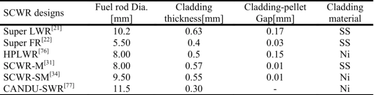
The details of six conceptual designs are listed in Table 1-2. The outlet temperature for all
Fig.1-11: Three pass flow scheme of HPLWR[30] Fig.1-12: Flow scheme of SCWR-M[32]
Fig.1-1313: Flow scheme of SCWR-R[3[37] Fig.1-1414: Flow scheme of CANDU-SCWR
conceptual designs achieves 500°C. However, the upper core structure is complex for Super LWR with two pass flow scheme, Super FR with all upward flow, HPLWR and SCWR-M due to the flow scheme. The refueling procedure will be complicate. The SCWR-R simplifies upper core structure by adopting single pass flow scheme. Use of zirconium hydride limits the maximum temperature at accident condition because of the hydrogen release.
Table 1-2: Summary of SCWR conceptual designs
Parameters Super
LWR[2121] Super FR
FR[2[22] HPLWR[30] SCWR-
M[3[31] SCWR-
R[35-38] CANDU-
SWR[40-42]
Organization Univ. of
Tokyo, Japan Waseda
Univ., Japan European
Commission SJTU, China KAERI, Ko
Korea AECL,
Canada Flow scheme Two-pass Two-pass Three-pass Two-pass One-pass One-pass
RPV Pressure
Vessel Pressure
Vessel Pressure
Vessel Pressure
Vessel Pressure
Vessel Pressure Tube
Spectrum Thermal Fast Thermal Thermal /
Fast Thermal Thermal
Fuel UOUO2 UOUO2/ MOX UOUO2 UOUO2 UOUO2 UO2 / Th
Moderator H2O H2O H2O H2O ZrH2 D2O
Thermal output[MW] 2740 2325 2597 3560 3182 2540
Efficiency[%] 44.4 44.4 44.4 44.4 44.4 4848
Operating pressure[MPa] 2525.0.0 2525.0.0 2525.0.0 2525.0.0 2525.0.0 2525.0.0
Inlet temperature[-C]C] 280 280 280 280 28080 350
Outlet temperature[-C]C] 500 501 500 510 510 625
Core flow rate[kg/s] 1342 1199 1160 1976 1540 1320
Core height[m] 4.2 3.6 4.2 4.50 / 2.40# 3.81 (
Core diameter[m] 3.68 1.86 3.4 3.30 3.93 4.00
Fuel Rod Dia.[mm] 10.2 5.50 8.00 8.00 9.50 11.5
Fuel Pitch[mm] 11.2 6.55 9.50 9.60 / 10.2# 11.5 13.5
Fuel cladding NiNi SSSS NiNi SSSS SSSS NiNi
Assembly shape Square Hexagon Square Square Square Circle
Power density[MW/m3] 6262.0.0 27274 58.0 102 67.6 (
*: Thermal zone / Fast zone
10 1.3.2 Super LWR design study
Super LWR is the thermal reactor cooled and moderated by supercritical water. The coolant density decreases substantially with temperature from inlet to outlet. It brings much challenge for core design due to the core power distribution strongly links to water density distribution. The R&D activities of Super LWR have been carried out to pursue an optimum conceptual design with high average outlet temperature and adequate neutron moderation under certain design criteria during 30 years study. At the initial stage of Super LWR, the zirconium-hydride rod was proposed to act as the moderator[6]. Then, it was replaced by water rods due to high enrichment and radioactivity waste of zirconium-hydride rod. There were three types of water rod(single tube, semi-double tube and full-double tube). The full-double tube was demonstrated to have better moderation than other two kinds of water rods[8]. Its performance was investigated with old criterion of limiting the heat flux[9]. In view of the relatively complex structure, the upward flow type single tube water rod was recommended and the core design with 400ZC outlet temperature was proposed[10]. To increase the average outlet temperature, a core with downward flow in single-tube water rod was designed.
Maximum cladding temperature criterion was introduced instead of critical heat flux of heat transfer deterioration[11]. The water at the top dome of reactor pressure vessel(RPV) which is derived from inlet coolant flows down through the water rod and mixes with the rest of inlet coolant from downcomer at the lower plenum, then the mixing flow rises up through the fuel channel. It effectively compensates the upper core insufficient moderation caused by the density decrease and the relatively flat axial power distribution can be achieved. Meanwhile, the high average outlet coolant temperature can be obtained since the low temperature moderator from water rod is mixed with coolant at core bottom. On account of such advantages, the design with downward flow type water rods was widely adopted and developed by the subsequent conceptual design in worldwide.
Yamaji, et al.[21]improved the design by adopting the square assembly as well as downward flow in water rods and in peripheral fuel assemblies to achieve the average temperature of 500ZC. He also improved the core calculation method from two-dimensional R-Z model to three-dimensional one for accurate evaluation of burn-up depending on the fuel assemblies[43]. Kamei, et al.[20]optimized the design by adopting the low neutron leakage fuel loading pattern and thermal insulator in water rod tube to reduce enrichment and thermal stress of stainless steel. In the program of HPLWR, the assembly adopting downward flow in single water rod and the core with three flow pass scheme were designed to meet the goal of 500ZC outlet temperature[26][30]. In recent years, the design with downward flow type water rod has begun to arouse the attention of researchers in China[44-46].
The upper core structure of the design with downward flow type water rod, however, will be complicated because of the application of moderator guide tubes, its connection to the fuel assemblies and the seals between hot and cold coolant interfaces. The fuel shuffling and control rod handling is difficult due to the complex upper core structure. Therefore, simplifying upper core structure while keeping the same design goals are important, on this view, several conceptual
designs aiming to simplify the upper core structure were proposed in the past few years. One design was the Japanese supercritical water-cooled reactor (JSCWR) developed by Ookawa, et al.[47]and Sakurai, et al.[48]. It was expected to simplify the upper core structure and refuel as LWR fuel assembly. JSCWR adopts bottom mounted control rod drives and cruciform control rods as a BWR.
The moderator is supplied to the water rod outside of the channel box by flow ducts at the top of the fuel assembly. It simplifies the upper core structure and refueling as LWR, but requires control rod drives from the bottom of the core. One of another design was to use zirconium hydride as the solid moderator[33-38][49-50]. Nevertheless, use of zirconium hydride limits the maximum temperature at accident condition because of the hydrogen release. The high enrichment is the other issue. The coolant density coefficient will be small. It needs to be evaluated carefully. In this study, an improved core design is developed to simplify the core structure.
1.3.3 Subchannel analysis of SCWR
Subchannel analysis is an important approach to evaluate the thermal hydraulic performance of a reactor core. It is even more important for SCWR due to the coolant temperature and density change greatly. The subchannel analysis has been conducted for Super LWR[51], Super FR[52-54], HPLWR[55-57], SCWR-M[31][58-59], SCWR-SM[60] and CANDU-SCWR[61-64]. The turbulent mixing rate of PWR is adopted since there was no thermal hydraulic experiment of supercritical water. The prediction formula of turbulent mixing rate coefficient was taken from the experiment of water(single phase). Single phase data did not take the account of density change. However, unlike PWR, the supercritical water density varies significantly around pseudocritical temperature. The experiment on mixing turbulent rate of supercritical fluid between subcannels was conducted at Kyusyu University using HFC134a as the test fluid. The test section is shown in Fig.1-15, the inlet flow for two pipes is the same, but the coolant temperature at the inlet is different. It made possible to measure only turbulent mixing at the mixing section. By changing the inlet coolant density of the pipes as liquid-liquid, liquid-vapour and vapour-vapour(liquid: coolant temperature is below pseudocritical temperature; vapor: coolant temperature is higher than pseudocritical temperature), the turbulent mixing rate is obtained in different condition. The results are compared with the KAWAH ARAeS FORMULAwhich is from PWR model as shown in Fig.1-16. The Repcis the Reynolds number at pseudo-critical temperature point. The turbulent mixing rate near pseudo-critical point in the liquid-vapor condition has far larger values in comparison with that predicted by the PWR model formula. It can be explained by the large density difference between subchannels. In the supercritical fluid, the density changes substantially around the pseudocritical temperature. At the condition of liquid-vapor around pseudocrtical temperature point, the density difference between two subchannels is large. It enhances the turbulent mixing rate between two adjacent subchannels. In this study, the subchannel analysis with turbulent mixing rate of supercritical fluid is conducted.
12
Fig.1-15: Outline of cross flow experiment at kyusyu University[65]
Fig.1-16:7 URBULENTMIXINGDATACOMPARISONWITH KAWAH ARAeAFORMULA[65]
1.4 Main research work of the thesis
1.4.1 Objectives of the study
Objective 1: Simplify core structure. The two pass core is widely adopted since it can achieve high outlet temperature and the axial density variation is mitigated due to the downward flow in water rod. The flow scheme of two pass core is shown in Fig.1-17(a). The upper core moderator
guide tubes make the upper core structure, fuel shuffling and control rod maneuvering be complicated. To simplify the upper core structure, the core with double tube water rods(double tube WR core) was proposed firstly as shown in Fig.1-17(b). The double water rod is composed of inner water rod(inner WR) and outer water rod(outer WR). The inlet flow flows down to the bottom dome. One part of flow enters inner water rod and turns direction to the outer water at the top of double tube water rod. Then, it is mixed with the other part of flow at lower mixing plenum and the mixing flow goes up through the fuel channel. The upper core moderator guide tubes are not necessary and the upper core structure is simplified. However, the lower part of core for double tube WR core is complicated. Therefore, the core with single pass flow is devised to further simplify core structure as shown in Fig.1-17(c). The water from bottom dome rises up in both water rods and fuel channels. The core structure is simple as PWR.
Fig.1-17: flow scheme of cores
Objective 2:2: Design a core achieving design goals and satisfying design criteria.The design targets of two pass core are listed in the followings[2020-2121]:
)ElElectric power scale of 1000MWe,
y
Net thermal efficiency of 43.8%,%,y
Coolant inlet and outlet temperature of 280-C and 500-C,C,y
Average power density close to that of current LWR(50 MWth/m3 of BWR ~ 100MWth/m3 of PWR),y
Average discharge burn-up of ~ 45GWD/tHM.As the design condition without undergoing remarkable modification from two pass core, they are employed as the guideline for the core conceptual designs of double tube WR core and single pass core. Regarding to the design criteria, negative void reactivity coefficient and shutdown
14
margin larger than 1%dk/k from conventional LWR is adopted. On the other hand, as the supercritical water has no phase change, the phenomenon of burn out of the subcritical heat transfer does not exist. The heat transfer deterioration will be much milder than that of burn out. The criterion of minimum critical heat flux ratio(MCHFR) from the subcritical-pressure is replaced by the criterion of maximum fuel rod cladding surface temperature(MCST). The design criteria should be satisfied by the core designs.
Objective 3: Conduct subchannel analysis by adopting supercritical fluid turbulent mixing rate. Comparing with PWR model, the turbulent mixing rate of supercritical fluid significantly increases around pseudocritical temperature. The subchannel analysis improvement using turbulent mixing rate coefficient of supercritical fluid over PWR model is investigated.
1.4.2 Organization structure of the thesis
This thesis is composed of six chapters. Each chapter is briefly introduced as followings:
Chapter 1is the introduction. It describes the necessary and purpose of the study.
Chapter 2describes the core design goals, criteria and calculation method. The determination for core design goals, criteria and parameters is introduced firstly. Then, the equilibrium core calculation method, which includes neutronic calculation, thermal hydraulic calculation as well as neutronic-thermal hydraulic coupling calculation, is presented. Finally, the subchannel analysis calculation is described.
Chapter 3is core design with double tube water rod. The fuel assembly design and core design are described in this chapter. The thermal hydraulic performance of double tube water rod is studied for optimizing design parameters. Then, the assembly with double tube water rod is designed for obtaining low pin power peaking and sufficient moderation. The neutronic and thermal hydraulic features of the equilibrium core are analyzed.
Chapter 4describes the core design with single pass flow scheme(single pass core design). The single pass core with low coolant temperature is designed with the purpose to reduce the burden of materials development. The relationship between outlet temperature and MCST is investigated.
Then, the design with and without considering control rod(CR) for high coolant temperature core is carried out respectively. The performance for each core design is presented.
Chapter 5is subchannel analysis for core design. It consists of two main parts. The first part is the evaluation of subchannel analysis improvement by employing turbulent mixing rate coefficient of supercritical fluid over PWR model. The performance of subchannel analysis improvement is analyzed on three kinds of fuel assemblies which are adopted in SCWR conceptual design. The second part introduces the optimization of single pass core assemblies by subchannel analysis. The geometrical parameters of fuel assembly are optimized to decrease the non-uniform of thermal hydraulic parameters over subchannels. The pressure drop of the single pass core is evaluated.
Chapter 6is the conclusion. The main results of the study are presented.
Chapter 2 Core design method
2.1 Core design criteria and goals 2.1.1
Design criteria of Super LWRDeveloping core design criteria of Super LWR is important as they instruct the R&D activities of Super LWR. The conventional LWR have developed their respective design criteria. As the Super LWR is cooled by light water, it has the similarities with conventional LWR. Some design criteria applied in conventional LWR can be adopted. On the other hand, comparing with subcritical pressure water, the supercritical pressure water has unique physics properties. The design criteria specialized for Super LWR is needed. Generally, the design criteria of Super LWR consist of thermal design criteria and neutronic design criteria.
Thermal design criteria
1. Design limitation for maximum linear heat generation rate(MLHGR)
Design limitation for MLHGR of Super LWR is determined to be 39kW/m for preventing fuel failure in abnormal transient situation[4]. MLHGR is an important design parameter in conventional LWR to prevent the PCMI(pellet-cladding mechanical interaction). The MLHGR is 44Kw/m in BWR. For PWR, the MLHGR can be set to 59.1Kw/m to keep the fuel rod centerline temperature below the melt point of 2300°C. By considering the pellet volumetric explanation at the accident of fuel rod melt, the MLHGR is determined to be 43.1Kw/m. It is corresponded to the fuel rod centerline temperature of 1900°C for keeping sufficient design margin. In fact, the PCMI is caused by the thermal expansion difference between UO2fuel and Zircaloy cladding. It is not a big issue in Super LWR since the stainless steel(SS), which has higher thermal expansion than UO2fuel, is applied. But releasing fission gas excessively should be prevented. Considering the higher coolant temperature comparing with conventional LWR, the MLHGR criterion is determined to be 39kW/m for ensuring the fuel centerline temperature below 1900ºC[21],which is similar to that of conventional LWR.
2. Design limitation for excess heat up of fuel rod cladding
As the supercritical water has no phase change, the design limitation for excess heat up of fuel rod cladding can be fulfilled by MCST. In conventional LWR, the coolant is worked in subcritical pressure condition. The excess heat up of fuel rod cladding is avoided by preventing occurrence of boiling crisis, which is used to describe the heat transfer deterioration resulting from the abrupt boiling mode change. Generally, the boiling crisis consists of the boiling crisis caused by the departure from nucleate boiling(DNB) for PWR and the boiling crisis resulting from the dry out for BWR. The heat flux where the boiling crisis occurs is referred as critical heat flux(CHF). The ratio of the CHF to the operating heat flux of the fuel rod, which is called as
16
minimum critical heat flux ratio(MCHFR), or the critical power of the fuel assembly to the operating power of the fuel assembly is chosen as the design criterion for excess heat up of fuel rod cladding in BWR[4]. For PWR, the minimum departure from nucleate boiling ratio(MDNBR) is employed as the criterion for excess heat up of fuel rod cladding. In the initial study phase of Super LWR, the similar design criterion of the minimum deterioration heat flux ratio(MDHFR), which is defined as the ratio of the deterioration heat flux to the maximum heat flux, is adopted to avoid the heat transfer deterioration occurred at the pseudocritical temperature which is similar to the boiling point at subcritical condition. The outlet temperature of the core is limited to 400°C[8-9]. While, since the supercritical water can be treated as the single phase, the heat transfer coefficient can be evaluated even at the pseudocrtical temperature. The heat transfer deterioration mechanism around pseudocritical temperature is evaluated by using numerical calculation based on the Jones-Lauder k- model[66]. The results are well agree with the experimental conducted by Yamagata et al[67]. Comparing with conventional LWR, the cladding temperature rise continuously and milder when the heat transfer deterioration is occurred[68]. Therefore, the criterion of MDHFR can be replaced by the criterion of MCST, which directly predicts the cladding temperature. The maximum cladding temperature criterion is determined by considering the cladding material strength. The MCST criterion takes the cladding oxidation corrosion into account. Considering the temperature difference of about 12°C between cladding surface temperature and cladding centerline temperature[4], the MCST is taken as the criterion for excess heat up of fuel rod cladding to prevent fuel failure. The value of MCST criterion must be verified by experiment. At abnormal transient in safety analysis, the MCST limitation is 850°C for the stainless steel to prevent fuel integrity. Considering the design margin, the MCST criterion is temporarily determined to be around 650°C at normal operation. The outlet temperature can be raised to 500°C. The thermal efficiency achieves 44.0%[11]with the inlet temperature of 280°C.
3. Moderator temperature in water rods less than pseudocritical temperature[20]
The moderator temperature in water rods should be kept below pseudocritical temperature to provide sufficient neutron moderation. As seen in Fig.1-4, the water density decreases substantially when the temperature exceeds the pseudocritical temperature. The neutron would be moderated insufficiently. The high enrichment is required for achieving criticality. On the other hand, the high enrichment would mitigate the shutdown margin.
Neutronic design criteria
1. Sufficient shutdown margin with one maximum worth control rod being stuck
Control rod insertion is the negative reactivity. The core should be in a cold state of shutdown when all control rods are inserted. Similar to conventional LWR, the shutdown margin should be larger than 1%dk/k assuming one maximum control rod(CR) being stuck.
2. Inherent safety features being kept for Super LWR
Inherent safety features indicate the core automatically falls to the safer side when the positive reactivity is inserted. As the reactor is cooled by light water, the Super LWR should possess positive density reactivity coefficient which means negative void reactivity coefficient, and negative Doppler reactivity coefficient as in conventional LWR.
2.1.2 Design goals of Super LWR 1. Electric power output larger than 1000MWe
Larger electric power output has scale merits which can improve the economics of plant. The large capital cost is required to build the power station. Increasing power output can reduce the ratio of capital cost for building the power station to the total cost. Hence, the economics is improved. On the other hand, determining the power scale should take the size of most power grid of utilities into account. Considering the next generation reactor replacing the old reactor, the electric power output scale is decided to be around 1000MMe.
2. Outlet temperature achieves around 500°C with the inlet temperature of 280°C
In the conventional supercritical fossil-fired power plant, the maximum steam temperature is 538ºC. To utilize the high-pressure steam turbine of conventional supercritical fossil-fired power plant without major design change, 500ºC steam temperature may be necessary. On the other
Fig.2-1 Relationship between thermal efficiency and core inlet temperature[4]
hand, since the criterion MDHFR can be replaced by the MCST criterion as introduced above, it is feasible to raise the outlet temperature to 500ºC. When the outlet temperature is given, the thermal efficiency changing with the core inlet temperature is shown in the Fig.2-1. The inlet temperature of 295°C gives highest thermal efficiency. But the difference is small at the outlet temperature of 500°C. On the other hand, lowering the inlet temperature can decrease the
18
feedwater heaters, which can decrease the size of the balance of plant(BOP). Considering above two factors, the inlet temperature of 280°C is selected for the core design[11].
3. Discharge burn-up around 45GWd/t
The discharge burn-up of 45GWD/t is determined by considering the improvement of economy and technical continuity in conventional LWR. For conventional LWR, capital cost takes up around 50%-60% of total cost and fuel cycle occupies just around 20%. The high ratio of capital cost to fuel cycle cost indicates the economy of power plant can be improved by increasing the capacity factor. While, shutting down for maintenance is necessary for plant. Hence, it is an effective way to raise the capacity factor by shortening maintenance period as well as extending operation cycle. There are two ways to prolong the operation cycle. The first way is to increase the fuel enrichment. The second way is to raise the fuel burn-up discharge. For the given fuel enrichment, increasing burn-up discharge indicates increasing the energy output per unit fuel mass. It also means fuel mass for unit energy output can be decreased. In Generation II reactors, the discharge burn-up is about 40GWd/t, it can be increased to around 60GWd/t after using new fuel technology. Therefore, combining with fuel cycle extension and discharge burn-up in conventional LWR, the discharge burn-up for Super LWR is provisionally determined to be 45GWd/Tu.
2.2 Design parameters
Generally, the design parameters for Super LWR can be sorted into assembly parameters design and core parameters design. They are determined to achieve design goals, satisfy criteria and pursue optimum core.
Fig.2-2: Hexagonal fuel assembly[10] Fig.2-3: Square fuel assembly[69]
2.2.1 Assembly design parameters
Assembly design is significantly important for core design since it affects the neutronic performance such as local power distribution and thermal hydraulic performance such as outlet temperature. The assembly parameters are composed of assembly shape, assembly size, water rod size, fuel rod size and fuel rod pitch.
Assembly shape. In recent core design of SCWR cooled and moderated by light water reactor, the assembly design is mainly based on PWR and BWR. At the initial Super LWR study, the PWR-type hexagonal assembly is developed[10] as shown in Fig.2-2. This type of assembly, however, introduces large local power peak and complex radial enrichment zoning is required. To flatten pin power distribution over the assembly, the square assembly is developed by Westinghouse Electric Company[6969]as given in Fig.2-3. Then, the Super LWR developed in University of Tokyo proposed
Fig.2-4: Square fuel assembly with outer water rod[1[18] Fig.2-5: Double-row fuel rod assembly[3131]
Fig.2-6: Japanese SCWR assembly[4949] Fig.2-7: HPLWR assembly[71]
one square fuel assembly with outer water rods surrounding the assembly to compensate the insufficient moderation at the outer region of assembly[19] as shown in Fig.2-4. For this assembly, the structure is relatively complex for manufacture. In the later study, the double-row fuel rods assembly is proposed in the SCWR-M for thermal region to provide uniform moderation for each
20
fuel rod across the assembly as shown in Fig.2-5[31]. The BWR-type assembly with the large size water rod located at the center of assembly is developed by Japan SCWR[49]as shown in Fig.2-6. To flatten pin power distribution, the complex radial enrichment zoning is needed. HPLWR proposed a small assembly with two-row fuel rods surrounding the center water rod as shown in Fig.2-7[70]. Four small assemblies constitute one group assembly sharing with one CR drive. It flattens moderation across assembly by the moderator in water rod and the gap between two small assemblies. The structure, while, would be complex for manufacture. As the follow-up study of Super LWR, the square shape of assembly is adopted for its relatively uniform pin power distribution. On the other hand, combining with the latest study of SCWR, the two-row fuel rod assembly can be developed for the merit of flat pin power distribution.
Assembly size, water rod size, fuel rod diameter and pitch. Once the assembly shape is decided, the assembly size, water rod size, fuel rod diameter and pitch can be determined according to the ratio of hydrogen to heavy metal(H/HM) and hydraulic performance of assembly. The assembly size should take the size of current PWR CR drive into account to utilize the existing CR drive without much change. Therefore, the assembly is designed to be larger than 22cm. The water rod size is one factor deciding H/HM. The large size of water rod provides high H/HM, which is desirable for the moderation. The fuel rod diameter is determined by considering the power density and refueling period. Large fuel rod diameter can prolong the refueling period. But the power density is decreased. The fuel pitch is related to H/HM and hydraulic performance. The large fuel pitch gives large H/HM, but it also indicates the gap between fuel rods is large, which will worsen the heat transfer.
2.2.2 Core design parameters
Core height and core diameter. The core size is determined by the total thermal power supposed to be achieved. Then, from the neutronic economy viewpoint, the ratio of core height to core diameter around 1 is better. On the other hand, the large ratio of core height to core diameter can benefit the thermal hydraulic stability and coolant outlet temperature increase. In advanced PWR, the core height is 4.2m. Considering technology inheritance, the same core height as PWR is recommended. The core diameter can be determined by the core height, expected core power density and expected total thermal power.
Number of core assembly. Setting the number of assemblies in core should consider the core diameter, assembly size and core symmetry. Once the core diameter can be roughly determined by the core height and expected thermal power, the range of assembly number can be roughly given by considering the assembly size. The exact number of core assemblies(N) should consider the core symmetry of multiple factor 4, refueling core batches of multiple factor mand one burnt assembly located at the center of core, which means the total number of assemblies in the core has the
relationship ofof N=4*n*m+1, where n is the integer. The initial core design parameters determination process is shown in Fig.2-8.
Fig.2-8: Core design initial parameters determination flow chart
2.3 Equilibrium core calculation method
Equilibrium core is a state that the characteristics of (n)burn-up cycle is identical to that of (n+1)burn-up cycle. It represents the main features of the design and is considered to be one appropriate way to develop new design concept. Actually, the core includes three stages. The first stage is initial core stage, in which different enrichment fresh assemblies are loaded across the core.
After one burn-up cycle, the core is shut down. The low reactivity assemblies are moved out and new fresh assemblies are loaded. During the refueling period, the rest burnt assemblies are reloaded.
Repeating the successive operation followed fuel shuffling, the core achieves a steady state with the same characteristics, which is referred as the equilibrium core stage. The stage from the initial core to the equilibrium core is called as the transition core stage. From the strict viewpoint, the core design study should consider above three core stages. But it is not an effective way to develop the new concept because of the calculation cost. Studying equilibrium core can save the calculation cost and is a good way for developing new design concept. On the other hand, for Super LWR, the water density changes relatively large along core height due to the large enthalpy increase from inlet to outlet. The axial moderation variation caused by water density change will greatly impact the neutronic performance of core. The neutronic performance change influences the water density distribution in turn. Hence, it is necessary to couple the neutronic calculation and thermal hydraulic calculation.
22 22 2.3.1 Neutronic calculation
The neutronic calculation is composed of cell depletion calculation, assembly depletion calculation and core depletion calculation. They are carried out by different code system, but connect each other.
Cell depletion calculation
The cell depletion calculation is executed on the collision probability calculation module(PIJ) of SRAC codes. It is a general neutronic calculation code and developed by Japan Atomic Energy Agency(JAEA)[71]. Cell depletion calculation is carried out based on deterministic theory. The depletion equation with reaction rates for fission, capture and (n, 2n) reactions are solved. Then, the atomic number densities of nuclides in the burn-up chain model changing with burn-up is obtained.
The general-purpose nuclear data library JENDL3.3 is adopted by the code. The energy range is divided into 62 fast energy groups and 45 thermal energy groups. In the cell depletion calculation, the energy groups will be collapsed into several fast and thermal energy groups. In PIJ module, 16 geometrical models which cover most of reactor cell burn-up calculation are available for the users.
It is possible for the users to model different cell according to the calculation requirement. The cell is divided by the meshes. The PIJ module is carried out based on the meshes, which is called as the sub-region. In the neutron flux calculation, the fast and thermal energy ranges are treated separately.
For thermal region, the neuron fluxes gradient is steeper than that for fast region. Calculation unit(T-region) requires finer spatial mesh division. It merges several sub -regions. Due to the neutron distribution in fast region and resonance energy range is much flat than that in thermal region, the finer spatial mesh division is unnecessary and the calculation unit(R-region) merges several T-regions. Then, the macro cross-sections can be obtained based on the requirement of assembly depletion calculation. For each macro cross-section set, it is formed by gathering several T-regions and is called as X-region. Taking the two row fuel rod assembly(see Fig.2-5), which is adopted in this thesis, as an example, over the assembly, each water rod is surrounded by the same
Fig.2-9: Cell model for cell depletion calculation
number of fuel rods. Therefore, the cell for depletion calculation can be modeled as shown in Fig.2- 9, which can be calculated by the geometrical model 16. Each mesh indicates the sub-region. The T-region division can be carried out based on sub-regions. Then, the macro cross-section sets are prepared based on X-region. The X-region division can be carried out according to the material distribution of T-regions. The T-regions with the same material can be merged into one X-region.
To model the different enrichment applying in the assembly, each fuel rod can be treated as different X-region. The coolant over the assembly can be treated as the coolant X-region for preparing coolant macro cross-section and the T-regions covered by water rod can be merged to the moderator X-region for moderator macro cross-section. The macro cross-section sets also is prepared by embedding burn-up changing. Then, the energy groups of 107 are collapsed to several energy groups for macro cross-section preparation.
Assembly depletion calculation
The assembly depletion calculation is carried on the code module of ASMBURN by referring to homogenized macro cross-section obtained from cell calculation. It combines flux calculation by collision probability method(CPM) and burn-up calculation by interpolating macroscopic cross section from cell burnup calculation. The CPM is similar to the PIJ of SRAC. The assembly depletion calculation is similar to the cell depletion calculation, the assembly is spatially divided into meshes by Sub-regions. T-region merges several Sub-regions, while, X-region put several T- regions together. However, different from SRAC calculation, the materials filling over the assembly is the macro cross-sections set from cell depletion calculation based on X-region in the cell. In other words, the material in assembly is specified by the macro cross-section sets. Then, the assembly homogenized macro cross-section sets are made based on the X-region and interpolating burn-up change. The energy group is further collapsed from cell burn-up calculation to lesser energy groups for core burn-up calculation.
Branching burn-up calculation
Branching burn-up calculation is a calculation module integrating cell burn-up calculation, assembly burn-up calculation and pin-power distribution calculation. It is used for handling density variation, fuel temperature change and so on. For Super LWR, the average outlet temperature is around 500°C with the inlet temperature of 280°C. The assemblies of core mostly stay at the condition with the average density. But there are some assemblies may deviate from the average condition, which need to be accurately evaluated. Therefore, the branching burn-up calculation was developed[4]. The branching burn-up calculation code is one script coupling SRAC, ASMBUN and post-process script. The calculation flow chart is shown in Fig.2-10. The cell cases with various density and fuel temperature which are expected to be obtained are calculated by SRAC incorporating burn-up change. At each case with certain fuel temperature and density, the assembly macro-cross section at different burn-up step is obtained by interpolating macro-cross section through burn-up region from cell depletion calculation. After the calculation of each case with
24 24
given fuel temperature and density, the pin power distribution ofof assembly isis evaluated by employing post-process script. It reflects the heterogeneity of the assembly, and referred as the heterogeneous form factor(HFF). Like the macro-cross section, the HFF is obtained at each burn-upup step, expected density and fuel temperature. It is prepared for local power distribution calculation interpolation executed in core depletion calculation. The calculations introduced above are integrated by the branching calculation script and implemented automatically.
Fig.2-1010: Branching burn-up calculation Core burn-up calculation
The three-dimension(3-D) core burnup depletion calculation is executed on COREBN, which provide multi-dimensional core burn-up calculation based on diffusion theory by interpolating the homogenized assembly cross section with different density, fuel temperature and burn-up. The core is spatially divided by different elements specified by the assembly homogenized macro-cross section to simulate the different assemblies loaded in the core. Considering fuel shuffling, the assembly in different burn-up cycle stage(fresh stage, first burn-up cycle stage, twice burnt cycle stage, et al.) is treated as different element by giving different burn-up. The element is further divided into meshes for neutron diffusision calculation as shown in Fig.2-11. By solving the neutron diffusion equations, the power for each mesh is obtained. With the burn-up proceeding, the material for each mesh is renewed by interpolating the assembly macro-cross section with water density, fuel temperature and burn-up. Regarding to the core burn-up calculation, there is no coupling function with water density change, therefore, the water density distribution and fuel temperature distribution is given by the user. On the other hand, in the core burn-up calculation, it is limited to evaluate the mesh-wise power due to the macro-cross section for the mesh is treated as the same. The additional calculation is required to evaluate the pin power distribution across the core, which is defined as the local power distribution. During the core burn-up depletion calculation, the energy groups are corresponded to that in assembly calculation.
Fig.2-11: COREBN calculation geometry(1/4 symmetric core)[4]
Pin power determination
Pin power reconstruction is performed to accurately evaluate the local power distribution, which strongly influence MCST, outlet temperature and power distribution. As introduced above, the core burn-up calculation only gives the power in mesh wise. Actually, to save the calculation time, each mesh divided in the core covers the region including several fuel pins in X-Y plane.
Therefore, it is necessary to evaluate the power distribution for each fuel pin by considering heterogeneous form factor(HFF) in assembly. Generally, the calculation involves the HFF, homogeneous pin power(HPP) and average assembly power(AAP). HFF reflects the heterogeneity within a fuel assembly and is the ratio of pin power to average power, which is tabulated by interpolating the burn-up, density and fuel temperature during assembly depletion calculation as introduced above. The HPP and AAP are generated from core depletion calculation, where the assembly is divided into fine meshes in X, Y and Z direction. HPP is defined as pin power of the homogenized fuel assembly calculated by interpolating nearest three meshes power as shown in Fig.2-12. According to the distance between the fuel rod center and the center of all meshes included in the assembly region, three meshes with shortest distance are chosen for HPP calculation by interpolating mesh power and distance. The AAP is the assembly average power over the meshes included in the assembly range. Then, the final pin power at Z horizontal plane could be obtained
- ý &%% ] ¯´´¯´´÷÷÷÷÷÷ ] ddr (2-1)
Wherekrr÷÷÷÷÷÷ is average homogeneous pin power,¯´´
¯´´÷÷÷÷÷÷ denotes the pin power distribution factor generated by core calculation.
26 26
Fig.2-12: HPP calculation process 2.3.2 Thermal hydraulic calculation
Thermal hydraulic calculation is carried out for evaluating thermal hydraulic performance of the core. It is import for Super LWR core design since the Super LWR is the thermal reactor in which the fission reaction is mostly induced by thermal neutron and strongly influenced by the water density. Generally, the thermal hydraulic calculation includes single channel analysis, sub-channel analysis and three dimensional computational fluid dynamics(CFD). The single channel analysis is the simple thermal hydraulic calculation method. The results obtained from single channel analysis only reflect basic thermal hydraulic performance of the core, such as average water density of the assembly and the cladding temperature peaking across the assembly. CFD is the most fundamental physical model. It is the effective way for study the thermal hydraulic performance of the assembly in details. The sub-channel analysis is the intermediate method and gives the intermediate thermal hydraulic performance of the core, such as cross flow between fuel channels, pressure drop and so on. At the initial core design stage, it is unnecessary to apply the CFD and sub-channel for thermal hydraulic calculation by considering calculation time. In this sub-section, the single channel calculation method is introduced, then, the sub-channel analysis calculation will be presented in details in the next section.
As one thermal hydraulic calculation method, two basic thermal hydraulic performance that average water density and the cladding temperature peaking over the assembly should be given by the single channel model calculation. As introduced above, the assembly in the core burn-up calculation is filled by the same homogenized material and usually axially divided into a number of divisions. For the meshes located at the same axial division, they are assumed to have the same water density, which is treated as the axial average division density. To evaluate the thermal hydraulic feedback to neutronic calculation, the axial average division density should be provided by the single channel model calculation. On the other hand, the cladding temperature peaking should be evaluated to ensure all fuel rods are effectively cooled and the design satisfies the design criteria.
The single channel calculation model SPROD is employed for the thermal hydraulic calculation at the initial core design stage. In this thesis, two kinds of SPROD are developed due to two different kinds of water rod are adopted. The first SPROD code is developed for double tube water rod, the second one is studied for single water rod which is similar to the code developed by university of Tokyo[2121].
SPROD for double tube water rod calculation 1. Circle calculation model
Fig.2-13: AsAssembly with double tube WR
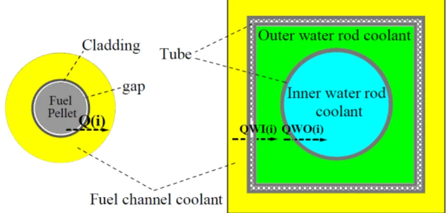
In order to simplify the upper core structure complicated by the upper core water rod guide tubes in two pass core, the double tube water rod is applied as shown in Fig.2-13. The double tube water rod(WR) is composed of inner water rod, outer water rod, outer water rod tube and inner water rod tube. The moderator enters inner water rod through the water rod orifice, which is installed on the lower tie plate, and it turns the direction to the outer water rod at the top of core. It is different from the single water rod as introduced by university of Tokyo[2121]. Not only the heat transfer from coolant to outer water rod is calculated, but also the heat transfer between outer water rod and inner water rod should be considered. Based on the unique structure of double tube water rod, the single channel is modeled as shown in Fig.2-14. Due to the square water rod is modeled as the equivalent circle water rod based the same water rod volume, this model calculation is defined as the circle single channel model. It is widely adopted in single channel analysis.
(1) Radial heat transfer calculation
Radial heat transfer calculation is carried out as seen in Fig.2-14, the radial heat transfer calculation should consider three heat transfer cases that heat transferred from fuel pellet to coolant Q(i), from coolant to outer water rod QWO(i) and from outer water rod to inner water rod QWI(i).
28 28
Heat transferred from fuel pellet to coolant involves fuel pellet heat transfer, gap heat transfer, cladding heat transfer and coolant transfer.
Fig.2-14: Circle single channel model for double tube WR calculation The equation of heat conduction in fuel pellet is shown in Eq.2-2[4].
Ë]½Ë½Ë½ ¿Î¾Å] ]½¸½¸½Ë½Ëéõèï ý ú¿Î¾Å (2-2) Where is the distance toto fuel pellet center,u¿Î¾Åis the fuel pellet temperature.¿Î¾Å is the fuel pellet heat density.¿Î¾Åis the thermal conductivity of fuel pellet. It can be expressed by Eq.2- 3[4].
¿Î¾Åý¸
éõèï G ù VGQSQS û QPQP ] u (2(2-3)
According to Eq.2-2 and Eq.2-3, the temperature drop from fuel pellet center to fuel pellet surface can be calculated by Eq.2-4[4].
^u¿Î¾Å ýÊéõèïÄ ]ËÚ
÷÷÷÷÷÷÷÷éõèï ýµÕÄéõèï
éõèïèï
÷÷÷÷÷÷÷÷ (2-4)
Where÷÷÷÷÷÷÷¿Î¾Åis the average thermal conductivity over the fuel pellet. s¿Î¾Åis the total heat generated by the fuel pellet.
The gap between fuel pellet and fuel cladding inner surface is applied, which is around 1mm at the beginning of fuel equilibrium cycle(BOEC) and filled by helium. With the burn-up proceeding, the fission product(FP) gases will accumulate.
Since there is no heat source in the gap, the heat conduction equation is different from that in fuel pellet. The heat source item at the right side of Eq.2-2 is replaced by 0 as shown in Eq.2-5[4].
Ë]½Ë½Ë½ ÀºÉ] ]½¸½¸½Ë½Ëêäò ý P (2-5)
WhereÀºÉ is the heat conductivity of gas,uÀºÉis the temperature in the gap at the position . Then, the temperature drop from the fuel pellet surface to the inner surface of cladding can be obtained based on Eq.2-6[4].
^uÀºÉ ý µéõèï
ÕóêäòÞóéõèïîêäò ]Ëéõèïý Õ]Áµéõèï
êäò]Ëéõèï (2-6)
Where ÀºÉ is the distance between inner surface of fuel cladding and fuel pellet center.~ÀºÉis the gas conductance in the gap.
Similar to gap heat transfer, there is no heat source for cladding heat transfer. The heat conduction equation is shown in Eq.2-7[4].
Ë]½Ë½ ¼Åº½½ÂÇÀ] ]½¸æïäççìðê½Ë ý P (2-7)
¼Åº½½ÂÇÀis the heat conductivity of the fuel cladding, u¼Åº½½ÂÇÀ is the temperature in the cladding at the position@. Therefore, the temperature difference between the inner surface and outer surface of cladding can be obtained as Eq.2-8[4].
^u¼Åº½½ÂÇÀý Õ]Á µéõèï
æïäççìðê]ËæïäççìðêNìððèó (2-8)
Where ¼Åº½½ÂÇÀNÂÇǾËis the position of the fuel rod cladding inner surface, ~¼Åº½½ÂÇÀis the conductance of the fuel rod cladding. It can be calculated as Eq.2-9[4].
~¼Åº½½ÂÇÀýË Äæïäççìðê
æïäççìðêNñõôèó ËæïäççìðêNìððèó (2-9)
The ratio of assembly fuel rods to water rods NNR is considered for the coolant thermal hydraulic diameter in calculation. In single channel model calculation, the coolant surrounding each fuel rod is treated as the same. Therefore, only the heat transferred from one fuel rod to its surrounding coolant is considered and treated as the fuel channel calculation unit. Since the water rod is surrounded by a number of fuel rods, the factor NNR should be taken into account for calculating the thermal hydraulic diameter in the fuel channel calculation unit. For the assembly with double tube water rod, due to the application of guide tube, the number of fuel rods surrounding each water rod is different over the assembly. It is 23 for corner water rod, 20 for inner water rod and 22 for outside water rod. Therefore, the average NNR of 21.75 over the assembly is adopted. The hydraulic diameter for fuel channel unit calculation can be calculated as Eq.2-10.
$& ýÕ] Ë ]
éõèï Ëãá²²¶ (2-10)
Where, ¹¶is the radius of the equivalent outer water rod."is the coolant flow area. Hence, the coolant temperature can be calculated by Eq.2-11.
1#,,); ý 10; úÕ]¯·Â ]¬¯µÂ (2-11)
30
Where, TCOOL(i), TS(i) and Q(i) are the coolant temperature, cladding temperature and heat rate at axial mesh i. HS(i) is the heat conductance to the coolant, it can be calculated by Eq.2-12.
&0; ý²ÎÂ]±Â¬¯ (2-12) Where,p is the Nusselt number of coolant,m is the thermal conductivity of the coolant.
Fuel channel - outer WR heat transfer
The moderator temperature in outer water rod can be obtained as Eq.2-13.
1*,; ý 1#,,); ú .2,; ] Õ]¬¯]¯·  ùÕ]¬¯³]¯·³  ùÕ]±¹³¸·³Â]¬¹³ (2-13) Where, TMO(i) and HSO(i) are defined as the temperature and heat conductance of moderator in outer water rod. QWO(i) is the heat transferred from the coolant to the moderator in outer water rod. TSO, KWO(i) and DWO are the thickness, heat conductance and outer surface diameter of outer water rod wall.
The first item at the right side of equation is coolant temperature, the second is heat transfer from coolant to outer surface of wall, the third is heat transfer from inner surface of water rod wall to moderator, the fourth is the water rod wall heat transfer.
Outer WR - inner WR heat transfer
Inner water rod heat transfer is similar to the outer water rod heat transfer. Hence, the similar equation is given to calculate the moderator temperature in inner water rod as shown in Eq.2-14.
1*'; ý 1*,;ú .2'; ] Õ]¬¯³]¯·³  ùÕ]¬¯°]¯·° ÂùÕ]±¹°¸·°Â]¬¹° (2-14) Where, the parameters in the equation are defined in the same way as in outer water rod.
(2) Axial heat transfer calculation
As the simple thermal hydraulic calculation, the single channel model takes into account of energy and mass conservation but neglects the pressure drop calculation. In the actual core, the flow rate is allocated by the orifice fixed on the assembly. However, the pressure drop in single channel model is not considered. It will be taken into account by subchannel analysis calculation. In the axial heat transfer calculation, the energy and mass conservation equations are taken as the basic physic equations and applied in both fuel channel and water rod.
Since the pressure drop is not considered, the pressure at each axial mesh is assumed to be the same for both fuel channel and water rod. The mass conservation for both fuel channel and water rod can be expressed by the Eq.2-15 and Eq.2-16.
Wc=Wc(1)=Wc(2)=Wc(i) (2-15)
WWm=WWm(1)=WWm(2)||=WWm(i) (2-16)
Where, W is the coolant flow rate in fuel channel, WW is the moderator flow rate in water rod.
![Table 1-1: Nuclear power plant development in the worldwide [2]](https://thumb-ap.123doks.com/thumbv2/123deta/9848474.1897277/6.892.158.763.514.791/table-nuclear-power-plant-development-worldwide.webp)