2017〜2019年度 関西大学研究拠点形成支援経費研 究成果報告書
著者 工藤 宏人, 宮前 翼, 上田 正人, 村山 憲弘, 林
順一, 松岡 光昭, 横山 佳帆, 大倉 滉平, 内藤 牧 男, 下山 大輔, 関谷 亮, 灰野 岳晴, 池田 勝彦, 森 重雄, 土井 研児, 北垣 壽, 寺内 俊太郎, 五十 井 浩平, 白杉 文香, 丸山 徹, Tamaki
Mitsuyoshi, Nakamura Keisuke, Nakamura Gou, 齋 藤 隆太, 仲村 利樹, 柳谷 仁志, Sakai Takahiro, 中本 光二, 山口 莉嘉, 藤田 智香, 福永 真理, 塩 月 康平, 竹田 紘也, 山本 洋揮, 古澤 孝弘, 渡邊 健夫, 大隈 修, 前 一廣, 鈴木 一誓, 柿沼 綾子, 小俣 孝久, 坂本 貴則, 今坂 怜史, 石井 甫泰, 荒 木 貞夫, 山本 秀樹, 大堀 静也, 小川 大貴,
Kitagawa Kouta, 関 あずさ, Sonoc Alexandru, Jeswiet Jacob, 芝田 隼次
発行年 2020
権利 2‑1 ネットワークポリマー事務局の許諾を得て公開
しています。
2‑4 日本金属学会の許諾を得て公開しています。
2‑6 This is a post‑peer‑review, pre‑copyedit version of an article published in
International Journal of Metalcasting. The final authenticated version is available online at
http://dx.doi.org/10.1007/s40962‑019‑00310‑7.
2‑7 This is a post‑peer‑review, pre‑copyedit version of an article published in
International Journal of Metalcasting. The final authenticated version is available online at:
http://dx.doi.org/10.1007/s40962‑018‑00292‑y.
2‑13 This is the accepted version of the article, which has been published in final form at DOI 10.1016/j.micromeso.2018.07.005.
2‑14 (C)フォトポリマー学会 この資料は著者最終 ...
URL http://hdl.handle.net/10112/00020715
1
Title:
Effect of Molten Metal Temperature on Mold Filling in Evaporative Pattern Casting
Authors:
Toru Maruyama1*, Mitsuyoshi Tamaki2, Gou Nakamura3 and Keisuke Nakamura2
1 Department of Chemistry and Materials Engineering, Kansai University, 3-3-35 Yamate-cho, Suita-shi, Osaka 564-8680, Japan
2 Yanmar Co. LTD.,
1-32 Chayamachi, Kita-ku, Osaka-shi, Osaka 530-8311, Japan
3 Aishin Takaoka Co. LTD.
1 Tenno, Takaokashinmachi, Toyota-shi, Aichi 473-8501, Japan
*Corresponding author:
E-mail: [email protected] Tel.: +81-6-6368-1121 Fax: +81-6-6368-0784
Abstract
The mold filling rate during evaporative pattern casting was measured in a wide range of molten metal temperatures from 800°C to 1450°C. A polystyrene columnar foam was used as the foamed pattern, and bottom pouring was applied to design the casting. Tin alloy, copper alloy, and cast iron were used as molten metals to vary the molten metal temperature. The mold filling rate increased with increasing molten metal temperature at relatively lower temperatures. In contrast, the mold filling rate decreased with increasing molten metal temperature at high temperatures. These phenomena were verified by in-situ observation.
Keywords: evaporative pattern casting, mold filling, molten metal temperature, pattern decomposition, polystyrene foam, in-situ observation.
2 Introduction
Evaporative pattern casting (EPC) is a unique net-shape metal casting process that utilizes polymer foam as the casting pattern [1]. The polymer foam is decomposed thermally by heat transferred from molten metal, and the molten metal fills into a cavity formed as a result of the thermal decomposition of the foamed pattern. Polystyrene is a common foam material compared to methyl methacrylate polymer. However, polystyrene residues are formed on the thermal decomposition products during casting, and these residues may cause casting defects [2-4]. To prevent defects caused by residues, sufficient thermal decompositions of foamed patterns and the discharge of thermal decomposition products from the cavity to back sand are required. Since the foamed pattern is decomposed by the heat transferred from molten metal, the mold filling rate is expected to increase with increasing molten metal temperature [5]. In contrast, mold filling rate may decrease with increasing molten metal temperature because a large amount of thermal decomposition gas is generated [6]. To understand the mold filling rate, it is helpful to refer to reports discussing the influence of molten metal temperature on the mold filling rates of molten aluminum alloys [5-15] and cast irons [15-19]. However, it is not appropriate to compare the mold filling rates of aluminum alloys and cast irons due to the large difference in their molten metal temperatures and molten metal densities. To investigate the influence of molten metal temperature on the mold filling rate, mold filling rates of various molten metal temperatures were measured. The molten metal temperature was widely varied from about 800°C to 1450°C, and various kind of alloys with similar densities were prepared to maintain the molten metal temperature during mold filling. To verify the correlation between the molten metal temperature and thermal decomposition of the foamed pattern, in-situ observation was carried out.
Experimental Procedures a. Mold Filling Experiments
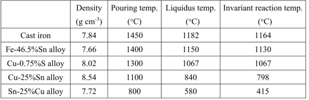
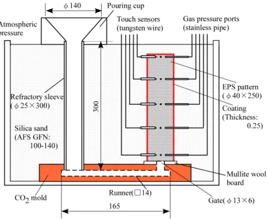
The bottom pouring method was applied to design the casting to avoid turbulence flow of the molten metal. The density of the foamed polystyrene pattern was 15.4 kg m–3. The dimensions of the foamed pattern were 40 mm in outer diameter and 250 mm in height. Coatings with permeability of 3.70 cm2 cmH2O-1 min-1 and thickness of 0.25 mm were applied on the foamed pattern. Touch sensors (tungsten wires) for molten metal, gas pressure ports (stainless steel tubes), and alumel-chromel thermocouples of 0.2 mm in diameter were inserted into the foamed pattern. As shown in Fig 1, sensor points were set at 5 mm, 65 mm, 125 mm, 185 mm and 245 mm from the bottom of the pattern. The sensors were arranged concentrically 5 mm from the pattern center. Silica sand with grain number of 100-140 AFS was used as backing sand. The sprue, runner, gate were molded using refractory materials. Vacuum was not applied during casting. Table 1 shows the densities of the alloy, pouring temperatures and solidification temperatures used for the mold filling experiments. Alloys with an invariant system were designed so that molten metal temperature can be maintained at temperatures close to the temperatures of invariant reactions, such as eutectic, monotectic, or peritectic reaction, during mold filling. Eutectic reaction can occur on the
3
cast iron and the Cu-S alloy, monotectic reaction on the Fe-Sn alloy, and preritectic reaction on the Cu-Sn alloys. The molten metal temperatures were measured with thermocouples inserted into the foamed pattern.
The pouring temperatures of the Sn-25%Cu alloy, Cu-25%Sn alloy, Cu-0.75%S alloy, Fe-46.5%Sn alloy, and cast iron (Fe-3.3%C-3.0%Si-0.3%Mn alloy) were 800°C, 1100°C, 1300°C, 1400°C and 1450°C, respectively. The required amount of molten metals was placed in a pouring cup and then poured into the sprue by removing the stopper at the bottom of the pouring cup.
b. In-situ Observation Experiments
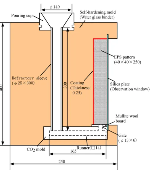
A similar type of casting design was used for the in-situ observation of mold filling. Figure 2 shows the casting design for the in-situ observation. A foamed polystyrene pattern of quadrangular prism with dimensions of 40 mm x 40 mm x 250 mm was used. The density of the foamed pattern was 11.4 kg m–3. A transparent silica plate with dimensions of 300 mm x 50 mm x 3 mm was attached to one side of the foamed pattern. Both the top and bottom ends of the silica plate were fixed with a bonded sand mold as shown in Fig. 2. Vertical grooves were made along the length of one side of the foamed pattern surface contacting the silica plate. The other sides of the foamed pattern were applied with a coating with the same permeability of 3.70 cm2 cmH2O-1 min-1 as the mold filling experiment. The backing sand was a self-hardening sand mold cured by water glass binder with silicate type curing agent. The molten metal used was cast iron, like the mold filling experiment. Molten cast iron of 6.6 kg was poured into the mold cavity in atmospheric pressure in the same way as the mold filling experiment.
Results and Discussion
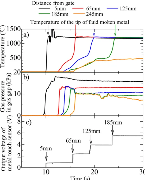
Figure 3 shows the result of actual sensor outputs during the mold filling of the molten cast iron poured at 1450°C. Figures 3 (a), (b), and (c) show the temperature, gas pressure, and metal touch sensor output at each sensor point, respectively. As shown in Figure 3 (c), one step of the voltage increment corresponds to the sensor position reached by the molten metal. As shown in Figure 3 (b), the start of increase in gas pressure corresponds to the position at which foamed pattern decomposition occurs in the gas pressure port.
As shown in Figure 3 (a), the molten metal temperature at each sensor point was evaluated as the maximum temperature shown on the thermocouple immediately after detection of the molten metal with the touch sensor.
Figure 4 shows the temperature at the tip of the molten metal at each sensor point. The temperatures tended to slightly decrease, and were close to the invariant temperatures. In the case of cast iron, no data could be obtained at the 245 mm position from the pattern bottom due to misrun. The cause of the misrun is not attributed to the drop in temperature at the tip of the molten cast iron because there is larger than eutectic temperature. The temperatures at 185 mm and 245 mm could not be obtained in the case of Fe-Sn alloy (1400°C of pouring temperature). The average temperatures during the mold filling of the Sn-Cu alloy, Cu-Sn alloy, Cu-S alloy, Fe-Sn alloy, and cast iron were 560°C, 890°C, 1030°C, 1100°C, and 1220°C,
4
respectively. The molten metal temperature may have decreased due to the decomposition heat of the foamed pattern. The decomposition heat of EPS is reported as 30 kJ/kg [20], and based on the EPS mass used in this experiment, 145 J of heat is required to decompose the entire pattern. On the other hand, since the heat capacity of the molten cast iron (about 2 kg) in the mold is about 1700 J/K, the decrease in molten metal temperature due to the decomposition heat of EPS should be very small.
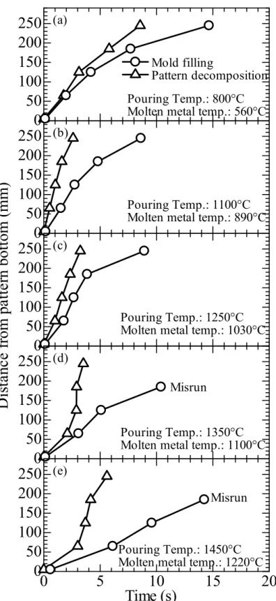
Figure 5 shows the progress of the foamed pattern decomposition and the mold filling of molten metals with time. The molten metal temperatures during mold filling in Figures 5 (a), (b), (c), (d), and (e) were 560°C, 890°C, 1030°C, 1100°C, and 1220°C, respectively. As shown in the figures, the foamed pattern decomposition and mold filling progressed with time. At the molten metal temperature range of 560°C to 1030°C, the rates of the pattern decomposition and mold filling decreased with time. On the other hand, when the molten metal temperature was over 1030°C, the initial rates of the pattern decomposition and mold filling were smaller than those in the latter half. The pattern decomposition rate at 1220°C was larger than that at 560°C, however, the mold filling rate at 1220°C was slower than that at 560°C. The mold filling rate is influenced by not only molten metal temperature, but other factors as well.
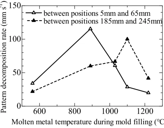
Figure 6 shows the relationship between the molten metal temperature and foamed pattern decomposition rate. The rates were calculated as a direct proportional from the results in Figure 5. The pattern decomposition rate between the 5 mm position and 65 mm position from the gate increased with increasing molten metal temperature from 560°C to 890°C, and decreased with further increase in the molten metal temperature. As for the 185 mm to 245 mm positions, the tendency of the pattern decomposition rate increasing once and decreasing with increasing molten metal temperature was similar with the 5 mm to 65 mm positions from the gate. The temperature in which the pattern decomposition rate between the185 mm and 245 mm positions becomes maximum was larger than that between the 5 mm and 65 mm positions. For the 185 mm to 245 mm positions, the amount of heat transferred from the molten metal to the foamed pattern may be smaller than the 5 mm to 65 mm positions because the distance between the pattern decomposition surface and molten metal tip is larger. These results indicate that the pattern decomposition rate increases with increasing molten metal temperature, however, the rate may decrease when the amount of heat transferred from the molten metal to the foamed pattern exceeds a certain amount due to the large gas gap.
Figure 7 shows the relationship between the molten metal temperature and mold filling rate. The mold filling rate increased with increasing molten metal temperature from 560°C to 890°C, and decreased with further increase in molten metal temperature regardless of the measurement position. These results show that the mold filling rate does not simply increase with increasing molten metal temperature. Similar results to Figure 7 have been reported [6, 15]. According to these reports, the mold filling rate increased with increasing molten metal temperature. In addition, the mold filling rate decreased due to a large amount of gas generated by thermal decomposition at high temperatures of the molten metal. At high temperatures of molten metals such as cast iron, the gas pressure in the thermal decomposition gas layer can be large because
5
a large amount of gas, such as low hydrocarbon, is formed due to the decomposition of monomer by the large amount of heat generated.
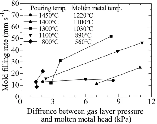
Figure 8 shows the influence of the difference between gas pressure in the thermal decomposition gas layer and head of molten metal on the mold filling rate at each sensor point. The mold filling rates at positions 65 mm, 125 mm, and 185 mm from the gate were estimated by averaging the mold filling rates from the sensor point to two adjacent sensor points. For example, the mold filling rate at 65 mm is the average rate for the 5 to 65 mm positions and 65 to 125 mm positions, while that at 245 mm is the average rate for the 185 mm to 245 mm positions. At the 5 mm position from the gate, the data was not plotted because the gas pressure could not be measured stably. The head of molten metal was calculated from the molten metal densities and positions of the molten metal tip. The molten metal densities except cast iron were estimated by proportionally converting the pure metal liquid density of alloying elements.
The molten cast iron density was set to 6.9 g cm-3. The mold filling rate tended to increase with increasing pressure difference. However, in the cases of molten metal temperatures of 1220°C and 1100°C, the mold filling rates were low despite the pressure difference. An increment in the pressure difference may be expected to increase the mold filling rate. In addition to the pressure of the thermal decomposition gas layer, the area for exhausting gas through the coated area should also be taken into account for understanding the results in Figure 8.
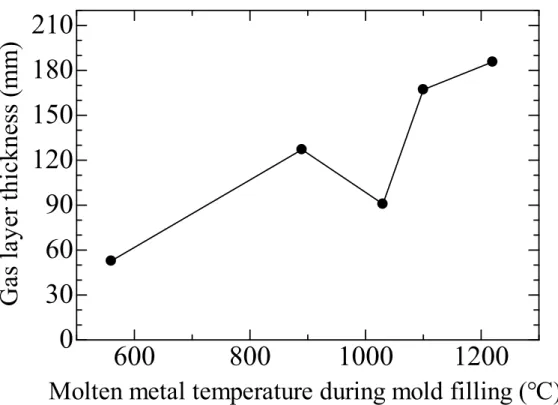
Figure 9 shows the relationship between the molten metal temperature and thickness of the thermal decomposition gas layer. Although the thickness of the gas layer tended to increase with molten metal temperature, the gas layer thickness specifically decreased at about 1030 °C. As shown in Figure 8, at 1030 °C, the mold filling rate is large at the pressure difference even when the gas gap is not large compared to the area from which gas is discharged. The decrement in the gas layer thickness indicates that the thermal decomposition gas volume is small in the case of 1030 °C. The amount of gas generated is small when polystyrene decomposes into monomer gas, whose boiling point is 145 °C. The gas layer at1030 °C became small because the amount of thermal decomposition products may be smaller than that at 1100 °C or more, and the heat generated from molten metal to foamed pattern may be larger than that at 890 °C or less. Therefore, the molten metal temperature of about 1000 °C seems to be the appropriate temperature for polystyrene foamed pattern. On the other hand, the reason for the slow mold filling rate in the case of molten cast iron could not be understood from the pressure difference and gas layer thickness. To understand the mold filling of molten cast iron, it is necessary to directly observe the thermal decomposition of the foamed pattern and flow of molten metal during mold filling.
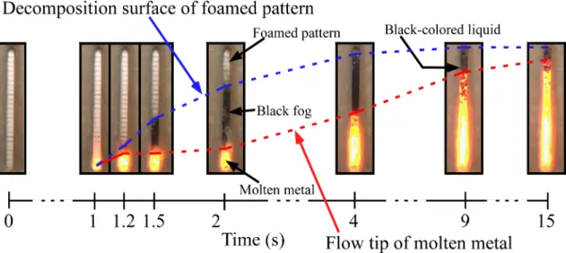
The results of Fig. 5 (e) suggest that the mold filling and the foamed pattern decomposition in the initial stage is very slow. To verify this phenomenon, we conducted in-situ observation. Figure 10 shows the states of the foamed pattern decomposition and the molten cast rion flow. From just after pouring to 1.2 s after pouring, the foamed pattern was decomposed and a cavity was formed, after which the molten metal flowed into the cavity. From 1.2 s to 2 s, two thirds of the foamed pattern decomposed like black fog, and the
6
molten metal flow more or less stopped at the position 1.2 s. After 2 s, the molten metal started to flow again. Black-colored liquid was observed near the molten metal tip. A part of the black liquid was absorbed into the area between the molten metal and silica plate while gasifying. Similar results have been reported in previous studies[15]. The molten metal then filled into the cavity which was formed by the thermal decomposition of the foamed pattern. However, the molten metal did not fill to the top end of the cavity.
This observation result supports the result of Fig. 5 (e). Although the details of the thermal decomposition gas layer could not be clearly observed due to the black fog, black-colored liquid was observed. The thermal decomposition residues collected during the mold filling of the molten cast iron were found to be dark- colored liquefied resin [19]. The presence of the black-colored liquefied resin residues indicates that polystyrene has decomposed into molecules smaller than monomer, and that large amounts of gas can form.
Black liquefied products seen by the in-situ observation were present on the molten metal, and these products later evaporated. In the temperature measurement data of Figure 5, at the positions of 65 mm, 125 mm, and 185 mm, the temperature increase rate was found to decrease just before the thermocouple touched the molten metal. This temperature changes were attributed to the endothermic reaction of boiling of liquefied products. In addition, the permeability of the coatings may have become small due to the penetration of the liquefied resin into the coatings [19]. Excessively high molten metal temperature is thought to cause the mold filling rate to decrease in the initial stage of mold filling. Since liquefied products were observed, it is thought that complete decomposition did not occur. However, when monomers decompose, the maximum gas amount is four times that of the monomer gas. In the case of PMMA, foamed patterns mainly decompose into gas. Therefore, the decrease in the mold filling rate in the initial stage may not occur because of the different mechanisms of thermal decomposition. To further understand this mechanism, observation with higher spatial and time resolution is required. Since the mechanism of thermal decomposition is considered to change at molten metal temperatures of 1100 °C or higher, quantitative evaluation of decomposition products is also necessary for understanding details. In future work, we hope to construct a model for predicting misrun and residue defects at high molten metal temperatures by clarifying decomposition reactions.
Conclusions
In this study, the flow length of molten metal, gas pressure in the gas gap, and temperature in the cavity were measured during evaporative pattern casting, and the mold filling rate and foamed polystyrene pattern decomposition rate were calculated. The molten metal temperature during mold filling was varied from 560°C to 1220°C. The filling of molten cast iron into the mold was verified by in-situ observation. The following conclusions were obtained:
(1) The pattern decomposition rate increases with increasing molten metal temperature, and decreases with further increase in molten metal temperature. The temperature at which the pattern decomposition rate decreases changed to higher temperatures as mold filling progressed.
7
(2) The mold filling rate increases with increasing molten metal temperature up to 890°C, and decreases with increasing temperature over 890°C, especially at the initial stage of mold filling.
(3) The mold filling rate tends to increase with increasing difference between pressure in the thermal decomposition gas layer and head of the molten metal tip. However, in the case of high temperatures, such as molten cast iron, the mold filling rate did not depend on the pressure difference.
(4) The thickness of the thermal decomposition gas layer increases with increasing molten metal temperature, however it deceases at about 1000 °C, then increases again.
(5) The results of in-situ observation showed that the mold filling speed in the initial stage is very slow even though the decomposition of polystyrene foam progressed, and this caused the foamed pattern to decompose into black-colored products.
References
[1] F. Sonnenberg (1992), Lost Foam Casting Made Simple, Schaumburg, American Foundry Society.
[2] T. Kobayashi, Y. Kasuya, IMONO, 64, 318-324 (1992).
[3] W. Sun, H. E. Littleton, C. E. Bates, Int. J. Cast Metals Research, 16, 549-553 (2003).
[4] T. N. Chakherlou, Y. V. Mahdinia, A. Akbari, 32, 162-169 (2011).
[5] C. E. Tseng, D. R. Askeland, Trans. Am. Foundry Soc., 111, 519-527 (1992).
[6] X. Yao, S. Shivkumar, Mater. Sci. & Technol., 13, 841-846 (1997).
[7] J. Zhu, I. Ohnaka, T. Ohmichi, K. Mineshita, Y. Yoshioka, J. Japan Foundry Eng. Society, 72, 715-719 (2000).
[8] Y. Liu, S. I. Bakhtiyarov, R. A. Overfelt, J. Mater. Science, 37, 2997-3003 (2002).
[9] J. Kuo, J. Chen, Y. Pan, W. Hwang, Mater. Trans., 44, 2169-2174 (2003).
[10] D. A. Caulk, M. Barone, Int. J. Metalcasting, 2, 29-45 (2008).
[11] D. A. Caulk, Int. J. Metalcasting, 3, 7-25 (2009).
[12] S. Koroyasu, J. Japan Foundry Eng. Society, 81, 377-383 (2009).
[13] S. Koroyasu, A. Ikenaga, Mater. Trans., 53, 224-228 (2012).
[13] S. Koroyasu, J. Japan Foundry Eng. Society, 86, 447-453 (2014).
[14] S. Koroyasu, J. Japan Foundry Eng. Society, 88, 192-197 (2016).
[15] M. Khodai, N. Parvin, J. Mater. Proces. Technol., 206, 1-6 (2008).
[16] S. M. H. Mirbagheri, H. Ashuri, N. Varahram, P. Davami, Int. J. Cast Metals Research, 16, 554-565 (2003).
[17] T. Maruyama, K. Katsuki, T. Kobayashi, J. Japan Foundry Eng. Society, 78, 53-58 (2006).
[18] J. Kang, Int. J. Mater. & Product Technol., 47, 188-199 (2013).
[19] T. Maruyama, G. Nakamura,, M. Tamaki, K. Nakamura, Int. J. Metalcasting, 11, 77-83 (2017).
[20] T. Kobayashi, Y. Kasuya, IMONO, 64, 192-197 (1992).
Table 1 Pouring temperature and physical properties of casting alloys.
Density (g cm-3)
Pouring temp.
(°C)
Liquidus temp.
(°C)
Invariant reaction temp.
(°C)
Cast iron 7.84 1450 1182 1164
Fe-46.5%Sn alloy 7.66 1400 1150 1130
Cu-0.75%S alloy 8.02 1300 1067 1067
Cu-25%Sn alloy 8.54 1100 840 798
Sn-25%Cu alloy 7.72 800 580 415
Figure 1. Casting design for measurement of mold filling rate and foamed pattern decomposition rate.
1◄◄1--<!>_1_40_---J►~I Pouring cup Touch sensors (tungsten wire) Atmospheric
pressure
CO2 mold Runner( □ 14)
165
Gas pressure ports (stainless pipe)
Coating (Thickness:
0.25)
Figure 2. Casting design for in-situ observation of mold filling rate and foamed pattern decomposition rate.
0 0 'Sf"
Pouring cup
Refractory sleeve
( </.> 25 X 300)
CO2 mold
I - -
Self-hardening mold (Water glass binder)
o Coating
0
M (Thickness:
0.25)
Runner( □ 14) 165
250
Mullite wool
Gate (</.> l3X6)
Figure 3. Results of sensor response during mold filling of the molten cast iron poured at 1450°C. (a) Temperature, (b) Gas pressure in gas gap, and (c) Sensor output of molten metal with touch sensors.
0 500 1000 1500 a)
Temperature of the tip of fluid molten metal Distance from gate
5mm 65mm 125mm 185mm 245mm
10 20 30
0 2 4 6 8
Time (s)
c)
5mm
65mm
125mm
185mm
0 10
as pr em per at ur e ( ℃ ) G essur e T vol put O ta ge of ut kP ga a) p ( s ga in h se V ( nsor ) ouc l t ta me 20
b)
Figure 4. Temperature at tip of molten metal at each sensor point.
0 50 100 150 200 250
500 600 700 800 900 1000 1100 1200 1300
1450°C 1400°C 1300°C 1100°C 800°C
Distance from pattern bottom (mm)
T em pe ra tu re a t tip o f mo lte n m eta l ( °C)
Pouring temperature
•
■•
Figure 5. Progress of EPS pattern decomposition and mold filling of molten metal with time. Molten metal temperatures during mold filling were (a) 560°C, (b) 890°C, (c) 1030°C, (d) 1100°C and (e) 1220°C.
0 50 100 150 200 250
D ist an ce f ro m pa tt er n bot tom ( m m)
Mold filling
Pattern decomposition
Pouring Temp.: 1100°C Molten metal temp.: 890°C
0 (b)
50 100 150 200 250 (a)
Pouring Temp.: 800°C Molten metal temp.: 560°C
0 50 100 150 200 250
Pouring Temp.: 1250°C Molten metal temp.: 1030°C (c)
0 50 100 150 200 250
Pouring Temp.: 1350°C Molten metal temp.: 1100°C (d)
Misrun
0 5 10 15 20
0 50 100 150 200 250
Time (s)
Pouring Temp.: 1450°C Molten metal temp.: 1220°C (e)
Misrun
Figure 6. Relationship between molten metal temperature and foamed pattern decomposition rate.
600 800 1000 1200
0 50 100 150
Molten metal temperature during mold filling (°C) Pa tte rn de co m pos ition r ate ( m m s -1 )
between positions 5mm and 65mm between positions 185mm and 245mm
_,..__
•
I \
I \
I \
I \
I \
\
\
\
\
\
•
Figure 7. Relationship between molten metal temperature and mold filling rate.
600 800 1000 1200
0 10 20 30 40 50 60
Molten metal temperature during mold filling (°C)
Mold f illing r ate ( m m s
-1) between positions 5mm and 65mm
between positions 185mm and 245mm
________
....
__--- ...
·---- .... ___
\ \\
\
Figure 8. Influence of difference between pressure in thermal decomposition gas layer and head of molten metal on mold filling rate.
0 3 6 9 12
0 10 20 30 40 50 60 70 80
Diffrence between gas layer pressure and molten metal head (kPa) M old fillin g ra te (mm s -1 )
1450°C 1220°C 1400°C 1100°C 1300°C 1030°C 1100°C 890°C 800°C 560°C
Pouring temp. Molten metal temp.
Figure 9. Relationship between molten metal temperature and thickness of thermal decomposition gas layer.
600 800 1000 1200
0 30 60 90 120 150 180 210
Molten metal temperature during mold filling (°C)
Gas laye r thickne ss ( m m )
Figure 10. Appearances of the foamed pattern decomposition and the molten metal flow.
Decomposition surface of foamed pattern
F amed pattern Black-colored liquid
.. ..
~