Generation and Hybrid Use of Natural Clean Energies
to realize the Low Carbon Society
S
AKAITatsuo
※, Y
OSHIOKAShuya
※※,
O
GAMIYoshifumi
※※※, L
IANBenning
※※※※,
K
AWAIYohei
※※※※※and K
AWAKITAHirohisa
※※※※※※1. INTRODUCTION
It is well known that the extensive emission of greenhouse gases(GHG) such as CO2 gas and freon gas during a long period up to the present society after the industri-al revolution in the 18th century is a fundamental reason causing the global warming and the climate change on our globe as reported in a lot of references1-3). In such a cir-cumstance, the average temperature during an entire year at the surface of the globe has been elevated about 1deg.C comparing the corresponding temperature at the in-dustrial revolution. Thus, mitigation or reduction of the global warming is one of the most important subject to keep the continuous development of human beings.
On the other hand, drying up of energy resources as fossil fuels is another serious problem to realize the sustainable development of our industrial society and our daily lives. Nuclear power would be a clean energy, since the fossil fuel is not used and CO2 gas is not emitted during the generation of the power. However, once a critical acci-dent is occurred in the nuclear plant, fundamental cruel damages take place over the
※ Professor, Department of Mechanical Engineering, College of Science and Engineering, Ritsumeikan University, 1-1-1 Nojihigashi, Kusatsu, Shiga, 525-8577 Japan
※※ Associate Professor, Department of Mechanical Engineering, College of Science and Engi-neering, Ritsumeikan University, 1-1-1 Nojihigashi, Kusatsu, Shiga, 525-8577 Japan
※※※ Professor, Department of Mechanical Engineering, College of Science and Engineering, Ritsumeikan University, 1-1-1 Nojihigashi, Kusatsu, Shiga, 525-8577 Japan
※※※※ Yamamoto Metal Technos, Co., Ltd., 4-7 Setoguchi 2-chome, Hirano-ku, Osaka, 547-0034 Japan
※※※※※ West Japan Railways Company, 4-24 Shibata 2-chome, Kita-ku, Osaka, 530-8341 Japan ※※※※※※ Ikuta Sanki Kogyo Co., Ltd., 6 Yokooji, Shimomisu, Tsujido-cho, Fushimi-ku, Kyoto,
612-8241 Japan
© The Policy Science Association of Ritsumeikan University: Journal of Policy Science, 2015. ISSN 1881-6703. Vol. 9., pp.3-23
wide area based on the radioactive attacks during a very long period, as experienced through several serious accidents actually occurred. Paying particular attention to this terrible risk for the nuclear power plant, we have to obtain some different kinds of energy resources without emission of any greenhouse gas.
From this point of view, various kinds of natural energy have been focused as energy resources to realize the sustainable development of the industrial society. The most typical example of such natural energies is the solar energy, and the technology to generate and use the electric power for the solar energy is extensively progressed by a lot of efforts of engineers and a wide variety of administrations of governments of the respective countries or areas. The second example of the natural energy is the wind energy produced by the movement of air surrounding our globe. We can generate some amount of electric power by using various types of wind mills without emission of CO2 gas. The conventional power generation by water mill or water turbine gives us a kind of clean energy, because the CO2 gas is not emitted in the process of the power generation. If some special technology is newly developed in this type of hydraulic power generation system, this can be a candidate of the effective clean energy.
Based on the above review, the solar energy, the wind energy and the water ener-gy can be typical examples as the clean enerener-gy without emission of any greenhouse gases. Among them, power plants for the solar energy are already developed and this type of power plant in the wide variety of the generation capacity is widely used to supply a certain amount of the electric power. Thus, we can easily use the appropriate capacity of the generation power plant depending on the individual requirement. Ac-cording to such a circumstance, the authors have attempted to develop new types of power generation systems for the wind energy and the water energy in this study. These new technologies together with solar energy plants can be effectively combined to realize the hybrid use of natural clean energies without any emission of the green-house gas.
2. FUNDAMENTAL FRAME OF THIS WORK
2.1 Energy Consumption and Energy Resources
Variation of the annual energy consumption in Japan since 1973 is indicated in Fig. 1 based on 2014 White Paper on Energy4). Due to the Lehman crisis (Lehman shock) in 2008, total annual energy consumption was clearly reduced after 2008. Such a reduction can be mainly attributed to the reduction of the energy consumption in the category of industrial societies. This trend is affected to cease the continuous
de-velopment of the gross domestic products (GDP) in Japan as shown by the red line in Fig.1. After the Lehman crisis, percentage of the energy consumption for transporta-tion, public welfare, home appliance and industries are almost constant as 23.1%, 20.0%, 14.3% and 42.6%, respectively.
On the other hand, variation of the annual energy supply for the respective re-sources of petroleum, coal, natural gas, nuclear, water and some other new energies is depicted in Fig.2. It is also found that the total energy supply is reduced after the above Lehman crisis. This reduction is caused by the reduction of petroleum supply and pausing the nuclear power plants due to the serious accident of the Fukushima Nuclear Power Plant in 2011. In order to compensate such a shortage of the energy supply, the supply of the petroleum and the natural gas was increased gradually as in-dicated in Fig.2. Of course, supply of petroleum and natural gas has to be continuous-ly increased after 2012 in order to cover the energy requirement in Japan.
In this place, if the entire energy supply is separated into the fossil fuel and the non-fossil energy, percentage of the fossil fuel occupies more than 90% so that the per-centage of the non-fossil energy is restricted within the small value of only 7.2%. Thus, if the energy supply is compensated by only the fossil fuels, emission of greenhouse gas in Japan has to be significantly increased. Since the risk of accidents of nuclear power plant cannot be ignored for everyone, the reasonable energy resources should
Fig.1 Variation of annual energy consumption in Japan4).
(Trillion Yen) Variation of GDP (1018 J) Transportation Public welfare Home appliance Industries
Energy consumption
G
ross
D
om
es
tic
Pr
oduct
Fiscal yearbe natural clean energies.
2.2 Concrete Target of New Clean Energies in This Work
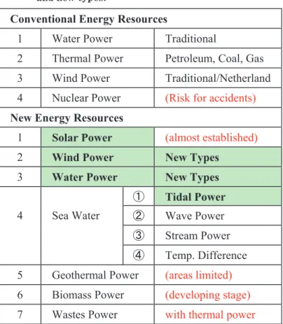
As discussed in INTRODUCTION, there can be various kinds of natural clean en-ergies without emission of greenhouse gas. Technologies of their power plants in the respective kinds of clean energies are at different stages from only tentative proposal as new energy resources to the completed technology to generate the energy and use it for the sake of our society. Table 1 indicates the overview of all the energy resourc-es including both of conventional and new kinds of energiresourc-es.
Among new energy resources in Table 1, technology for the power generating sys-tem in the solar energy is already established in the worldwide scale. A lot of big scale power plants were constructed as Mega Solar Systems in various countries. Thus, this type of clean energy was not accepted as the target of this study, since one can use this type of clean energy by setting the developed solar systems. From this point of view, the authors have selected the respective new energies of 2.Wind Power(New Types), 3.Water Power(New Types) and 4-①Tidal Power as main targets in the present work.
Of course, technologies on the remaining new energies in Table 1 should be es-tablished in the future as potential clean energies without emission of greenhouse gases. In addition, hybrid use of several different types of clean energy power plants is another important subject to be solved soon, since each type of power plant has both
Fig.2 Variation of annual energy supply in Japan4).
Fos sil fu el N on -f os sil Fiscal year (1018 J) Energy supply Petroleum Natural gas Water Coal Nuclear New energy
of advantageous and disadvantageous points depending on the individual method. This is also one of the target in this work.
3. DEVELOPMENT OF NEW TYPE OF WIND-MILL POWER
PLANT
3.1 Meteorological Situation of Wind in Japan
Useful applications of wind-mill power plants to irrigate the agricultural land and to remove the water into the sea have been carried out for a long time at some specific areas such as Netherland, where wind-mills were also used to mill various cereals and to machine a lot of wooden products especially in the district of Saanse Schans5). Such historical type of wind-mills were designed to use the drag force instead of the lifting force. Usually, the drag force acting to the wing is smaller than the lifting force
Table 1 Overview of all the energy resources in conventional and new types.
Conventional Energy Resources
1 Water Power Traditional
2 Thermal Power Petroleum, Coal, Gas 3 Wind Power Traditional/Netherland 4 Nuclear Power (Risk for accidents)
New Energy Resources
1 Solar Power (almost established)
2 Wind Power New Types
3 Water Power New Types
4 Sea Water
① Tidal Power
② Wave Power ③ Stream Power ④ Temp. Difference 5 Geothermal Power (areas limited) 6 Biomass Power (developing stage) 7 Wastes Power with thermal power
acting the wing. From this aspect of the wing, the most popular type of the present wind-mills are designed as to use the lifting force instead of the drag force. Thus, the wind-mill having three wings is the most popular type at the present all over the world6).
However, this type of wind-mill has a superiority of the performance, only if the direction of wind is steadily constant during the entire year. Such a situation can be realized only the limited areas on the entire globe. In Japan, the wind direction is al-ways changing depending on the variation of the meteorological conditions in high frequency. In such a circumstance, the setting direction of the wind-mill should be adjusted minute by minute as to be faced to the wind direction always in order to re-alize the high efficiency to pick up the wind energy7, 8).
Figure 3 indicates observation results on frequency distributions of the wind di-rection and the wind velocity on the roof of a building “Excel III” in Biwako-Kusatsu campus of Ritsumeikan University, Kusatsu, Shiga, Japan, in 20109). It is found that the frequency distribution of the wind direction tends to be governed by the surrounding conditions such as other buildings and mountains. In the present examples, a certain preferential direction was found between S and SE as shown in Fig.3(a), but the fre-quency is very low in the wide range of the direction of SSW-ECE. Such an aspect can be attributed to the fact that the site of this wind-mill is located between high build-ings in directions of NW and ENE.
On the other hand, the wind velocity gives high value in the range of WSW-NNW
Fig.3 Frequency distributions of wind direction and wind velocity9).
and the direction of S as seen in Fig.3(b). Thus, the frequency distribution of the wind direction is not corresponding to the trend on the distribution characteristics of the wind velocity. In other words, directions of WSW, W, WNW, NW and NNW give the high velocity of the wind, although the frequency of the wind direction in the corre-sponding directions is within fairly low level. Therefore, we have to consider the most efficient combination of the wind direction and the wind velocity to provide the maxi-mum power generation. Even if the frequency of a definite direction is in the low level, the situation of high velocity can generate the distinct wind power in the correspond-ing short period.
In order to realize such an effective application of the wind-mill, the facing direc-tion of the popular type of the wind-mill having three wings should be adjusted in high frequency minute by minute. However, if fairy amount of electricity is consumed to adjust the facing direction, this type of wind-mill power plant has no meaning as a clean energy generator.
In the next place, Fig.4 indicates the observation result on the one-dimensional distribution of the wind velocity during the entire year of 2010. The histogram indi-cates its frequency distribution, whereas the red line gives the cumulative frequency of the wind velocity. The highest frequency was confirmed at the velocity band of 0.5-1.0 m/s and the frequency tends to decrease gradually with an increase of the wind
Fig.4 Distribution of wind velocity during an entire year of 2010. 0 10 20 30 40 50 60 70 80 90 100 0 5 10 15 20 25 30
C
u
m
u
la
te
d
fr
e
q
u
e
n
c
y(
%
)
F
re
q
u
e
n
c
y(
%
)
Wind speed (m/s) 出現頻度(%) 累積出現頻度(%) Wind velocity (m/s) Fr eq ue nc y (% ) Cumulative frequency (% ) Appearing frequency Cumulative frequencyvelocity. Such distribution characteristics can be well represented by the following two-parameter Weibull distribution10, 11);
, (1)
, (2)
where Eq.(1) is the probability density function and Eq.(2) the cumulative distribution function, respectively. Values of the respective parameters can be easily obtained by means of the least squares method11, 12). Mean of the wind velocity, V
m, is given by
(3)
and the power density of the wind, PD, is given as follows;
, (4)
where ρ is the density of air given as ρ =1.225kg/m3 and Γ(·) is the gamma-function. Based on Eqs.(3) and (4), mean of the wind velocity and the wind power density are calculated as Vm=1.40m/s and PD=4.09W/m3, respectively. Here, considering the
distribution characteristics of the wind velocity in Fig.4, we have to develop the high efficiency wind-mill working within the wide range of the wind velocity of 0-6m/s. This is a very important point to achieve the high efficiency, when the wind-mill is designed in accordance with the actual distribution pattern in Fig.4.
3.2 Development of New Type of Wind-Mill
If the wind direction and the wind velocity are both kept under a definite condi-tion, the popular type of wind-mill having three wings occupies the highest efficiency to generate the electric power6). However, the meteorological feature of the wind is complicated so that the combination of the wind direction and the wind velocity should be simultaneously evaluated to design the wind-mill having a high efficiency, as indicated in the previous section. From this point of view, the authors have devel-oped a new type of wind-mill working well regardless of the variation of the wind di-rection9). Another important function is to keep the ability of the power generation in the wide range of the wind velocity.
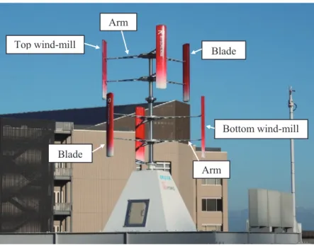
which three blades are vertically fixed at the tips of three arms in the top half of the central pole and the same structure of three blades wind-mill is mounted in the bot-tom half of the central pole. Three blades of the top and botbot-tom wind-mills are fixed at equal circumferential angle of 120deg, but a gap of the circumferential phase of 60deg. is given between the top and bottom wind-mills. If both wind-mills are fixed at the same phase, the following difficulty would take place at the starting of the wind-mill; if the wind begins to blow to the direction facing to one blade, remaining two blades are located at both sides in symmetry. In such a situation, this wind-mill can-not start the revolution, since the symmetrical two blades cancan-not produce any mo-ment due to self-balance of the momo-ments. This is the reason why a gap is introduced between the top and bottom wind-mills. Results indicated in Fig.3 and Fig.4 are ob-tained at the same site as indicated in the picture of Fig.5.
Figure 6 illustrates the variation of the relative wind velocity toward the blades and the lifting force acting to the blade during an entire revolution of the wind-mill, where a definite wind having a given velocity is blowing to the right hand side from the left hand side. In this study, shape of the wing section was designated accepting a popular example of NACA4412 and the angle of attack was set as -2deg., respectively. The wind velocity is represented by the common horizontal line (light blue arrow)
Fig.5 Picture of new type of wind-mil developed in this work. Top wind-mill Bottom wind-mill Blade Blade Arm Arm
having the same length at every instance of the revolution. During a revolution of the wind-mill, the blade has a certain velocity in the tangential direction, even if the air does not move (the wind does not blow). Therefore, the air velocity acting the tangential direction due to the revolution of the wind-mill is provided as shown by dark blue arrows. In such circumstances, the resultant velocity of the air toward the blade has different direction (green arrow) depending on the instance during a revolu-tion of the wind-mill. The lifting force to the blade acts perpendicular to the resultant velocity as indicated by red arrows in Fig.6. The acting direction of the lifting force thus analyzed is not passing through the center of the revolution. Accordingly, a cer-tain amount of rotating moment should act to the central pole so that an electric pow-er can be genpow-erated by this moment.
As shown in Fig.4, the wind velocity is varying in the wide distribution range during an entire year. Sometimes, the strong wind can blow from a certain direction
Running direction
Running direction
Fig.6 Variation of relative wind velocity and lifting force acting to blades during a revolution of the wind-mill.
during a short period, but the weak wind tends to blow frequently depending on the distribution characteristics in Fig.4. In other words, the effective wind to generate the significant electric power can take place only in the very low frequency and, therefore, the wind-mill has to be exposed in the weak wind circumstance during a long period. This is a very common disadvantage for the wind-mill type power plants regardless of the constructed places.
In order to overcome this difficulty, the authors have developed a new type of the electric power generating system by combining four electric generators. In this sys-tem, four of the same type generators are installed inside the pyramid box at the foot of the wind-mill generation system in Fig.5. Then, the number of working generators are adjusted depending on the revolution speed of the wind-mill as follows; no genera-tor for 0-15rpm, 1 generagenera-tor for 15-80rpm, 2 generagenera-tors for 80-120rpm, 3 generagenera-tors for 120-140rpm and 4 generators for the revolution speed higher than 140rpm.
3.3 Confirmation of the Fundamental Performance for the Developed System Among all the experimental data during the entire year of 2010, we can find the convenient results obtained during 6:00AM-12:00AM on November 9, where the wind velocity was in the wide range of 0-15.3m/s and the average velocity was 3.90m/s. In such a circumstance, the revolution speed was also in the wide range of 0-154rpm. Thus, we can confirm the fundamental performance of the developed power genera-tion system under any number of working generators from 1 to 4. In order to keep the safety of the working system, this wind-mill was designed to pause the revolution by means of a breaking system automatically when the revolution speed exceeds the up-per limit (155rpm).
Figure 7(a) indicates the relationship between output of the generator and the revolution speed of the wind-mill under the condition that only one generator is work-ing. It is found that the output tends to increase gradually with an increase of the rev-olution speed. On the other hand, its relationship obtained under the condition that every generator can work depending on the wind velocity is depicted in Fig.7(b). The output increasing behavior has the first step at the revolution speed of 80rpm, and the second step and the third step at the revolution speeds of 120rpm and 140rpm, respec-tively. Such steps appear based on the increase of the number of working generators. The solid red line extrapolated to the high revolution speed region in Fig.7(b) is a copy of the corresponding curve in Fig.7(a).
If we use only one generator, the output at the maximum speed of 155rpm is about 220W. But, the output at the speed is increased up to about 900W when every generator can work. Thus, it is finally concluded that the total output of four
genera-tors are always higher than the output of only one generator. Here, we have a funda-mental question whether a big scale generator with a high capacity can generate a significant electric power rather than one set of multi-type generators developed in this study. As indicated by the dashed red line in Fig.7(b), such kind of big scale gener-ator requires a high value of the wind velocity starting the wind-mill revolution due to the total resistance of the generating system. In order to start the revolution of the wind-mill installed a big scale generator having such a high capacity, the wind veloci-ty has to exceed the critical level, for instance, the wind velociveloci-ty giving the revolution speed of 120rpm in the case of Fig.7(b). Although the detailed behavior of the big-scale generator is not clear, it is sure that the lower bound of the wind velocity to start the revolution of the wind-mill is much higher than the corresponding velocity in the case of one small generator in this study. In other words, the new electric power generation system developed here can efficiently produce the electric power under the wind con-ditions in which the big scale generator cannot work in the low velocity range.
4. DEVELOPMENT OF NEW TYPE OF MICRO-HYDROPOWER
SYSTEM
4.1 Mechanism causing the Tidal Energy
Level of the sea water is always changing depending on the relative locations of the sun, the earth and the moon. In the definite season, The sun, the earth and the moon are arrayed linearly as shown in Fig.8(a), but they are allocated in the L-shape locations in the other season as illustrated in Fig.8(b). Since a certain attraction force has to act between each pair of heavenly bodies, the sea water is attracted to the
Fig.7 Relationship between output of power and revolution speed. (a) Only one generator working (b) Every generator working
0 200 400 600 800 1000 0 20 40 60 80 100 120 140 160 O ut put of p ow er (W ) Revolution speed (rpm) 0 200 400 600 800 1000 0 20 40 60 80 100 120 140 160 O ut put of p ow er (W ) Revolution speed (rpm)
nearest bodies. Thus, the sea water around the earth tends to be pulled in both direc-tions to the moon and the sun as indicated in Fig.8(a), whereas the sea water tend to be pulled to the direction to the moon rather than to the sun due to the short distance between the earth and the moon as shown in Fig.8(b).
On the other hand, the earth is rotating one time every day (during 24 hours) in every season. Accordingly, any site of the seashore has to pass through the deep and shallow areas of the sea water. This is the reason why the tidal phenomenon
consist-ing of high water and low water takes place two times every day as illustrated at the bottom of Fig.8. In the season of Fig.8(a), difference of high and low water levels be-comes distinct due to the superimposed effect by the sun and the moon, while the difference becomes small in the season of Fig.8(b) due to a lack of direction of attrac-tion forces by the sun and the moon. In this way, the tidal phenomena of the spring tide and the neap tide take place, and the high water and the low water have to occur two times during every day.
4.2 Development of Micro-hydropower System based on Tidal Energy
If a small bay is closed by a wall at a moment of the high water, a certain kind of dam appears after a few hours due to the tidal phenomenon of the sea water. Since the potential energy for the high water is larger than the energy for the low water, the high water tends to flow to the area for the low water. If we can generate the electric power
Fig.8 Celestial mechanism to cause spring tide and neap tide during an entire year.
1 day
1 day (b) Neap Tide
by such a flow of the water, we can obtain some amount of the clean energy indepen-dent on the weather13). In the case of wind-mill generator, the system cannot generate any electric power when the wind does not blow. Other type of the power generator by the solar panel cannot generate the electric power at night and rainy days. In such circumstances, the tidal energy can be picked up every day regardless of natural con-ditions such as the weather and the difference of night or daytime.
From this point of view, the authors have developed a power generation system in Fig.9 in order to extract the tidal energy in the sea water14). Tank 1 and Tank 2 are put such that Tank 1 is higher than Tank 2 and these tanks are connected by a pipe as shown in Fig.9. A spiral screw15) was mounted inside this pipe to drive the generator. By using 4 pumps, the water in Tank 2 is conveyed into Tank 1 to realize the definite difference of the levels in both tanks. One of 4 pumps has a special function to be ad-justed the flow quantity, and the difference of water levels in both tanks can be adjust-ed at any level by adjusting the water flow of this pump. Thus, we can simulate the tidal phenomenon by means of the present system in the laboratory, where the volume capacity of both tanks is 1m3, approximately.
By using this power generation system, output of the electric power was mea-sured by setting four different water levels of 60cm, 75cm, 90cm and 105cm, respec-tively. Experimental results thus obtained are depicted in Fig.10. It is found that the
Fig.9 Power generation system based on the tidal phenomenon.
Level 2 Level 1 Tank 2 Tank 1 Water flow Water flow
output of the power tends to increase with an increase of the water level difference. The output at the level difference of 60cm was saturated to 5W, the output at the dif-ference of 75cm tended to 11W, the output at the difdif-ference of 90cm to 18W and the output at the difference of 105cm to 23W, approximately. This fact means that we can generate the electric power of 23W by the water flow with the volume of 1m3. If the sea water within the distance of 10m along the seashore is used in this type of the power generation system, we can generate the electric power of 23W×10=230W. Similarly, if the sea water along the seashore of 100m, we can obtain the electric power of 23W×100=2300W=2.3kW. In addition, if we use the sea water 10m(distance from water front)×100m(seashore length)×1m(depth)=1000m3, we can generate the electric power of 23kW as easily calculated in the same manner. The electric power of 23kW can oc-cupy the power requirement of daily life for 10 -20 houses. This fact means that the electric power required to a small village consisting of 10-20 houses can be provided by this type of micro-hydropower generation system. Of course, one can use this elec-tric power as any kind of the power source required to the village such as street lamps and various applications for the port facilities.
In this study, the micro-hydropower system was applied to pick up the tidal ener-gy as an attempt. But, this system can be easily applied to extract the clean enerener-gy from the stream in small rivers, for example. In addition, if a certain volume of the rain water is stored in a tank, this water can be transformed into some amount of the electric power by applying the present micro-hydropower system. In such a way, this system can be usefully applied to different energy sources everywhere the medium is
Fig.10 Output of power versus setting current.
0
5
10
15
20
25
0 0.5 1 1.5 2 2.5 3 3.5 4 4.5 5
Level difference × 105cm 90cm 75cm 60cmSetting current (A)
O ut put of p ow er (W )
fluid such as sea water and pure water.
5. PROSPECTS OF ACTIVE USE OF NATURAL CLEAN
ENER-GIES AND SOME SUBJECTS TO BE SOLVED IN THE FUTURE
5.1 Hybrid Use of Some Different Types of Natural Energies
As introduced in Table 1, there can be a lot of natural clean energies such as solar energy, wind energy, water energy, geothermal energy and biomass energy. Various types of power plants have been developed for the respective energy sources and aw-ful efforts have been accumulated to improve the efficiency of individual type of the power plant. In such a history to create the clean energy, combination of different types of the power generation systems is also an important subject to keep the stabi-lized power sources.
Figure 11 indicates the overview to use every kind of clean energy generation sys-tem in accordance with local conditions peculiar to the corresponding areas such as the mountain side, urban area and seashore. In the area near the mountain summit, it is suggested that strong wind tends to blow in high frequency and obstacles are less to receive the sunshine. Thus, combination of the wind-mill type power plant and the solar panel power plant is an effective attempt to obtain the enough energy. However,
Fig.11 Overview of hybrid use of different types of natural energies on the earth.
Smart house Smart village Smart city Low carbon society
Mountain side
Ocean side Summit: Strong wind
① Wind energy ② Solar energy
Narrow river
Middle river Wide river
Urban area: Many buildings
① Micro-hydraulic ② Wind energy ③ Solar energy Volcano Geothermal energy Seashore ① Tidal energy ② Wind energy ③ Solar energy Mid-slope of mountain ① Micro-hydraulic ② Solar energy ③ Conventional water Sun Cloud Cloud Rain
in the area of mid-slope mountains, there are many narrow rivers and wide rivers de-pending on the geographical features and we can easily keep a wide space to put the solar panels. In such a circumstance, the micro-hydropower plant and the solar panel power plant are effective. If a large scale of dams can be constructed at the conve-nient places, the conventional type of water power plants are also effective to obtain sufficient amount of the clean energy.
On the other hand, in the area along the coast line, we can generate the electric power by using the tidal energy power plants. Usually the wind tends to blow strongly in the seashore, since the obstacles to the wind are considerably less. In addition, the solar panel power plants are also meaningful, since the seashore is convenient to re-ceive the sunshine. In this way, the tidal energy, the wind energy and the solar energy can be extracted effectively in the area along the coast line. Additional energy gener-ated by the wave can be obtained in the area of seashore, if we apply the wave power plants here.
Nowadays, a lot of high buildings have been constructed in the urban areas of the big cities. Since the wind tends to blow strongly on the roofs of those buildings com-paring with the ground level, the wind-mill type power plants have a superiority to extract the clean energy. If solar panels are facilitated on the roofs of those buildings, the solar energy can be extracted simultaneously. It is another aspect that a big vol-ume of water is always used in the each floor of the buildings for daily lives or daily works. This water has been discharged after used in each floor to the drain pipe con-nected to the drainage canal on the ground level. The volume of the drain water is not so small and the water has the definite potential energy governed by the location (height). Thus, we can extract a certain amount of electric power based on the poten-tial energy of the water by means of the micro-hydropower plants. In rainy days, the rain fell down on the roof can be added to the daily drains of a building. Therefore, sum of the daily drain and the rain can be used as clean energy sources for the mi-cro-hydropower plants. If we use the rain in such a way, a lot of buildings in the urban area can keep a big volume of rain water inside each building. This aspect provides an effective method to prevent the urban area flood frequently caused at the intensive heavy rain due to the furnished pavements in the usual cities.
It is finally noted that we should extract all kinds of clean energies effectively in accordance with the respective conditions at the given districts where the power plants are constructed. In other words, the appropriate hybrid use of different types of power plants is preferable to obtain the sufficient amount of the clean energies. If each family tries to use some kinds of clean energies, their house can be a “smart house”, and if every family in a village tries to use some kinds of clean energies, their
village should be called as “smart village”. Furthermore, if every family, every compa-ny, every school and every part of our city try to use some kinds of clean energies, our city becomes “smart city”. Based on such efforts by every person and every part of the society, the low carbon society can be realized in the future.
5.2 Subjects to be Solved in The Future
Fundamental performances of new type of the wind-mill power system and the mi-cro-hydropower system have been confirmed experimentally in this study. As another type of the power plant, the electric power generation system using solar panels has been already developed and such a kind of the power plants is now at the stage devel-oping the application areas. The above micro-hydropower system can be used to the wide variety of the applications such as tidal phenomenon, narrow rivers, small dams, and water stream in the buildings. The annual variation of the wind blowing is exten-sively depending on the geographical features in the corresponding districts. Feasibil-ity to receive the sunshine also depends on the geographical features and the artificial constructions such as houses and high buildings. The volume and speed of the water stream in the river are not the same depending on the location such as mountain side and the rural area. There are a lot of high buildings in the urban area and big amount of water is used and exhausted to the drainage exit as explained in the previous sec-tion.
Considering these actual conditions peculiar to each site, the most preferable method to generate the clean energy should be selected and several effective methods should be accepted as a hybrid types of the power generation plants in many cases. Each power generation system has some advantageous points together with some dis-advantageous points depending on the respective generation systems. Accordingly, if some different methods are successfully combined, one can obtain the sufficient out-put of the clean energy. In the night period, the solar energy generation plant cannot work as a generator, but the wind-mill type power plants can create the energy when the wind is blowing. In such a way, effective combination of different power genera-tion systems can provide us steadily the sufficient electric power.
However, in some cases, every generation method cannot work if inconvenient conditions are superimposed unfortunately. In order to solve this problem, the au-thors would like to recommend to combine an artificial generation method with the above hybrid generation system. Among various kinds of thermal energies (Fossil en-ergies), the emission of CO2 gas is least in the case of LPG fuel. Based on this aspect, the artificial power generation system by using the LPG is recommended to be com-bined with the above hybrid generation system. In such a situation, one can generate
the definite power energy by consuming some amount of the LPG, even if every power generation system cannot work due to the unfortunate superimposing the inconve-nient conditions.
6. CONCLUDING REMARKS
As new types of clean energy generation systems, a special wind-mill type power generation system and a micro-hydropower generation system have been developed here. Since the power generation system by using solar panels is already popular, we can easily construct the solar power plants. Geothermal energy and biomass energy are also reliable energy sources without emission of CO2 gas. In such circumstances, the authors have developed a concept of the hybrid use of several different power gen-eration systems which are suitable to the respective districts from meteorological and geophysical viewpoints.
Disadvantageous point for these power generation systems is the fact that the power generation ability significantly depends on the natural conditions at the given location. In some cases, every clean energy plant cannot work, if inconvenient condi-tions are superimposed, unfortunately. In order to overcome this difficulty, the au-thors have proposed the effective combination of a thermal energy generation system by the LPG fuel with the above clean energy generation systems. Thus, we can keep the sufficient energy by working various kinds of clean energy power plants together with some additional thermal energy produced by LPG fuel, where a little amount of CO2 gas would be exhausted.
The electric power generated by the present plants can be sold to the electric power companies in the respective areas and the electric power can be used by means of the usual network systems for transmission of the electricity. However, there are so many areas where the above transmission networks are not facilitated from both scales of nationwide and worldwide. In such areas, an appropriate size of the clean energy power plants can supply the electric power to the costumers directly without the long distance transmission networks. In other words, the clean energy can be cre-ated and can be consumed inside the corresponding area only preparing the short distance network system.
In this study, the nuclear power plants were not discussed due to the awful risk at the unexpected accidents actually taken place at some countries including Japan. Ab-solute safety cannot be provided, even if the highest technology is applied to the clear power plants. The present government in Japan is leading to reworking the nu-clear power plants in corporation to the related enterprises and the economical
soci-ety. However, a huge amount of budget is required to establish the post-treatment process for the used nuclear fuel, and the awful defective effects at further accidents cannot be recovered by any efforts of human beings.
In such a circumstance, the authors have to assert the importance of the develop-ment of the clean energy generation systems, instead of the nuclear power plants and thermal energy power plants using fossil fuels. In order to facilitate such a trend, some kinds of political plan should be established nationwide in Japan in reference to the policy and the movement in the international activity such as proposal by IPCC. In conclusion, the research and developments of the clean energy generation systems should be carried out under the reasonable ground plan in the respective countries paying particular attention to the international activities.
References
1 ) IPCC, The 5th Assessment Report, AR5, Working Group I (Climate Change), The Physical Science Basis Summary for Policymakers, (2013).
2 ) Ministry of Environment, Japan, Annual Report on the Environment, the Sound Materi-al-Cycle Society, and Biodiversity in Japan, (2014).
3 ) T. Sakai and K. Amano, “Realization of resources saving and reduction of global environ-mental load based on expansion of design life for industrial products”, Journal of Environ-mental Conservation Engineering, Vol.37, No.9, (2008), pp.39-45.
4 ) Ministry of Economy, Trade and Industries, Japan, 2014 White Paper on Energy, (2014), pp.140-141.
5 ) http://www.geocities.co.jp/PowderRoom-Tulip/5552/za-susekannsu.htm
6 ) H. Matsumiya, S. Aoki and M. Iida, Wind Power Generation, Kogyo Chosakai Publishing Co., Ltd., (2005), pp.21-26.
7 ) F. Tanaka, K. Kawaguchi and M. Tomioka, “Study on wind measurements and annual ener-gy production of a Darrieus wind turbine”, Journal of the Japan Society of Mechanical En-gineers, Ser.B, Vol.73, No.735, (2007), pp.111-117.
8 ) F. Tanaka, K. Kawaguchi, S. Sugimoto and M. Tomioka, “Influence of wing section and wing setting angle on the starting performance of a Darrieus wind turbine”, Journal of the Japan Society of Mechanical Engineers, Ser.B, Vol.74, No.739, (2008), pp.624-631.
9 ) Y. Kawai, B. Lian, N. Shirakawa, K. Konishi, H. kawakita, S. Yoshioka and T. Sakai, “Wind Measurement in BKC building roof and fundamental analysis on generation characteristics of a vertical axis wind turbine with straight blades”, Proceedings of EcoDesign 2010, (CD-R).
10) W. Weibull, “A statistical distribution of wide applicability”, Journal of Applied Mechanics, Vol.18, (1951), pp.293-297.
11) T. Sakai and T. Tanaka, “Estimation of three parameters of Weibull distribution in relation to parameter estimation of fatigue life distribution”, Journal of the Society of Materials Science, Japan, Vpl.29, No.316, (1980), pp.17-23.
12) T. Sakai and T. Tanaka, “Parameter estimation of Weibull-type-fatigue life distributions including non-failure probability”, Proceedings of FATIGUEʼ84, Vol.2, (1984), pp.1125-1137. 13) S. Yanabu and H. Nishikawa, Energy Transformation Engineering, Tokyo Denki
14) B. Lian, Y. kawai, T. Sakai, A. Ueno, N. Shirakawa, K. Konishi, H. Kawakita, H. Nogami and K. Okada, “Modeling and some experimental results of micro-hydropower system using tidal energy”, Proceedings of EcoDesign 2010, (CD-R).