• 検索結果がありません。

Node Mobility Aware Routing for Mobile Ad Hoc Network

N/A
N/A
Protected

Academic year: 2021

シェア "Node Mobility Aware Routing for Mobile Ad Hoc Network"

Copied!
5
0
0

読み込み中.... (全文を見る)

全文

(1)

LETTER Special Section on Next Generation Networks Software

Node Mobility Aware Routing for Mobile Ad Hoc Network

Shinichi FURUSHO

†a)

, Teruaki KITASUKA

, Tsuneo NAKANISHI

†,††

, Nonmembers, and Akira FUKUDA

, Member

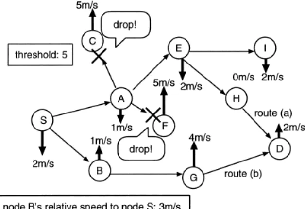
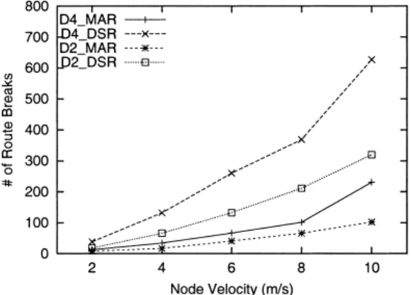
SUMMARY In ad-hoc on-demand routing algorithm, when a route is broken a relay node must perform error transaction and the source node must do rerouting to discover an alternate route. It is important to construct a stable route when route discovery occurs. In this paper, we use relative speeds among nodes as a measure of node mobility. Our routing algorithm chooses nodes of lower relative speed as relay nodes. As a result of our simulation, when there is one session in the network, our proposing algo- rithm can reduce the number of route breaks: about 3 times smaller than DSR. And our proposing algorithm can deliver more packets than DSR:

18% higher rate. However, in the congested tra ffi c situation our algorithm should be improved.

key words: relative speed, ad hoc network, routing protocol, DSR

1. Introduction

In the ad hoc network, mobile nodes can construct a net- work by self-organizing method and need no network in- frastructures. Intermediate nodes transmit packets when its neighbors can not communicate with each other directly.

Each mobile node must manage routes because there are no centralized infrastructures which control mobile nodes and packets in the network. Although routing operates flooding basically, flooding algorithm wastes machine resources and network band width, and causes communication failure by packet congestion [1]. An efficient route control is required because mobile nodes have to save their power consumption in the environment where they work only with their batter- ies. Many routing algorithms have proposed to solve those problems [2], [3].

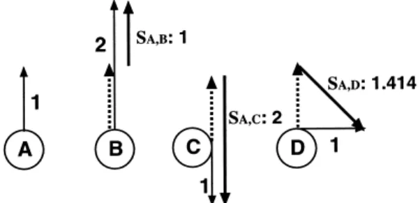
Movement information is information peculiar to mo- bile environment. There is the feature in the movement na- ture of a mobile node. Considering movement of mobile nodes, mobile nodes are subjected to restriction for their movement due to limitation such as buildings and roads in a town where ad hoc network is expected to be used. For example, people mostly move forward or backward along streets. Until now, there hardly is opportunity to discuss movement tendency of mobile nodes. It is thought that more efficient route control is attained by using the movement in- formation, such as speed and direction of nodes.

Manuscript received November 14, 2003.

Manuscript revised January 21, 2004.

The authors are with Graduate School of Information Science and Electorical Engineering, Kyushu University, Kasuga-shi, 816- 8580 Japan.

††

The author is with System LSI Research Center, Kyushu Uni- versity, Kasuga-shi, 816-8580 Japan.

a) E-mail: [email protected]

We introduce relative speed to measure mobile node’s movement information and use relative speed to choose a stable route. In this paper, we propose a new routing algo- rithm applying relative speed concept to on-demand routing protocol DSR [4].

2. Node Mobility Aware Routing

2.1 Relative Speed and Link Connectivity

As nodes move, the two neighbors can not communicate when they go out of each other’s radio range. If the rela- tive speed between two nodes is so fast, the link is broken in shorter period. So link breaks occur frequently. Therefore, we choose nodes of slower relative speeds as relay nodes to construct a stable route and reduce link breaks.

Generally, relative speed represents the vector of differ- ence between 2 nodes. In this paper, we ignore the direction and regard the length of the vector as the relative speed. We express relative speed between node i and node j as S

i,j

.

In Fig. 1, the relative speed of node B to node A is 1, that of node C to node A is 2 and that of node D to node A is 1.414, when the speed of node A, B, C and D are 1, 2, 1 and 1 respectively.

2.2 Route Discovery

Our proposing algorithm is an on-demand routing based on DSR (Dynamic Source Routing) [4].

A source node broadcasts a RREQ (Route Request) packet to find a route for a destination node when the source node needs to communicate with the destination node. A RREQ packet includes two pieces of additional information:

a threshold and a route cost. The pieces of route cost is the

Fig. 1 Relative speed (S

i,j

).

(2)

sum of relative speed of links on the route. The threshold is a fixed number set up initially and the route cost is initial- ized to 0 by the source node. On receiving a RREQ packet, if the node is not the destination node, adding with DSR pro- cess, it compares its relative speed to its previous node with the threshold. If the relative speed is greater than the thresh- old the node drops the packet. Otherwise, it adds its relative speed to the route cost in the packet and rebroadcasts it. Re- peating this process, the destination node receives RREQ packets from several routes. If the relative speed between the destination node and its previous node is less than the threshold, the destination node adds its relative speed to the route cost in the packet. An RREQ packet has cost of the route from the source node to the destination node at the point.

For each of the routes, the destination node returns a RREP packet to the source node including a copy of the route information, the source route and the route cost. The source node can know the route to the destination node and the route cost of the route from the RREP packet. After re- ceiving the RREP packet, the source node sends data pack- ets for the route obtained from the RREP packet. The source node may receive other RREP packets from different routes while sending data packets. The source node compares the routes and selects either route which has smaller route cost for a communication route. The source node sends data packets through a new route next time.

Figure 2 illustrates an example of our routing algo- rithm. Node S is attempting to discover a route to node D.

Threshold is 5. Node A’s relative speed to node S is 1 and node B’s relative speed is 3. On receiving the RREQ from node S, node A and node B compare these relative speeds to node S with the threshold. These nodes add these relative speeds, 1 and 3, to the route cost in the packets and rebroad- cast packets, because these nodes’ relative speeds are less than the threshold. Node C, node E and node F receive the RREQ packet from node A. Node C, node E and node F also do same process. However, node C and node F drop the packets because these relative speeds to node A, 6, are faster than the threshold. Node E adds its relative speed, 1, to the route cost, by which the route cost in the packet becomes

Fig. 2 Broadcasting RREQ.

2. Node G receives the RREQ packet from node B. Node H and node I receive from node E. Node G, node H and node I performs same transactions. Finally, node D receives two RREQ packets from route (a), S-A-E-H-D, and route (b), S- B-G-D. The route cost of route (a) is 6, since relative speed of each link, S

S,A

, S

A,E

, S

E,H

and S

H,D

are 1, 1, 2, and 2 re- spectively. That of route (b) is 8, since S

S,B

, S

B,G

and S

G,D

are 3, 3, and 2.

For each route, node D returns a RREP packet includ- ing route information. Node S may receive a RREP packet from route (b) earlier than route (a), we assumed. On receiv- ing RREP packet from route (b), node S starts to send data packets to node D along route (b). RREP packet from route (a) arrives at node S later. Node S compares route (a) and route (b), then chooses route (a) for a communication route because route cost of route (a) is less than that of route (b).

Then node S sends data packets along route (a) next time.

Our routing method controls propagation of ine ff ective packets by dropping RREQ packets which have faster rel- ative speed than threshold. Our routing method also con- structs a stable route composed of nodes of similar mobility to chooses the route of the lowest route cost.

It is important to select optimum value of threshold. If the threshold is small enough, a network can reduce many inefficient packets and chooses a more stable link. But it causes that a node can not discover existing routes in the network due to sinking down packets that reach a destina- tion node. On the other hand, if the threshold is big, packets are prone to reach a destination node. But the nodes of high relative speed are chosen as relay nodes. That causes fre- quent route breaks and rerouting process.

A communication node uses both route cost and thresh- old to choose a node having similar mobility as a relay node.

If a node that transmits packets moves fast, nodes that move fast and move to the similar direction are likely to be chosen as relay nodes. Therefore, it is not able to say that the node with slow or no movement is easy to be chosen as the relay node at all time. In the case that transmit nodes move at sim- ilar speed and to similar direction with each other, a certain node can be the relay node of these transmit nodes and traf- fic center on the relay node. However, we aim to choose the relay node which has similar mobility to a transmit node for the sake of reducing link breaks. If a transmit node chooses the relay node at random completely as far as it find, traffic does not center on a certain node. However, the link on the route breaks sooner because relay nodes may move to the opposite direction each other.

2.2.1 Route Cache

The node which obtains the route information to an other

node by RREQ and RREP packets puts the route informa-

tion into route cache. The source node can send data packets

without performing route discovery process if it has route in-

formation in its route cache. In our proposal, when receiving

RREQ or RREP packets, the nodes put not only route infor-

mation but also route cost into route cache. If route cache

(3)

has the same route information as that in the packet already, the node updates the route cost information of the route in cache for new value.

When the source node uses route information in route cache to send data packets, the source node chooses the route of the lowest route cost if route cache has several routes for the destination node. If the route cost of the routes is same, the route which has less hop counts is chosen.

When route discovery processes, if a relay node receiv- ing a RREQ packet has the route information to the destina- tion node in its route cache, the relay node can reply to the RREQ packet and does not rebroadcast the RREQ packet.

The relay node connects the route information in the packet (from source node to itself) to the route in the route cache (from itself to destination node) and adds route cost in the route cache to that in the packet. The node puts these in- formation into RREP packet. If the node does not have the route cost in its route cache, the node sets infinite value as route cost in RREP packet. Then the node sends it to the source node.

DSR operates promiscuous mode [5]. On the other hand, our proposing algorithm does not operate promiscu- ous mode. Therefore, our algorithm only puts route infor- mation which has route cost into route cache. However, the case where route information in route cache does not have route cost could still happen. This case occurs in the follow- ing situation. When node A gets route information to node D, node A puts the route information into its route cache.

The route information is made up of the list of nodes and the route cost to node D. This time, node A knows the route to node X which is the relay node on the route to node D. How- ever, node A does not know the route cost to node X only knows that to node D. Therefore, node A does not know the route cost to node X when node A receives RREQ to node X and replies to it.

3. Evaluation

3.1 Environment

We evaluated our routing algorithm proposed in Sect. 2 by using ns-2 network simulator [6]. We randomly located 160 nodes that have 250 m transmission range of a 1000 m square field. A source node and a destination node are 850 m distance from each other. The source node and the destina- tion node do not move. A source node generates 512 bit data packet with constant bit rate (CBR). 4 packets are generated per second.

Movement of mobile nodes are restricted by build- ings or streets in a town. In this simulation, mobile nodes move according to the Random Waypoint Mobility Model restricted in the direction. Each node moves only in the di- rection along with X or Y axis. We evaluate the cases that nodes move only in 2 directions along with Y axis and 4 directions along with X or Y axis. We evaluated our algo- rithm repeatedly as changing node velocity for each simu- lation. We set a node velocity of 2, 4, 6, 8, and 10 meters

per second and pause time of 0 second for the simulation. In the case of the simulation where node velocity is set to be 2 m / s, all nodes move to the destination at 2 m / s. On arriving at the destination, nodes move to a new destination at 2 m/s immediately.

We set the threshold 100 m/s. When the threshold is 100 no relay node drops RREQ packets even if its relative speed is high because the largest relative speed is 20 m/s (the fastest node moves 10 m/s). We simulated 20 times for each node velocity and ran the simulation for 100 seconds.

We disable DSR flowstate (dsragent enable flowstate=false in dsragent). DSR flowstate tries to use the route that used the last time if possible. However, MAR tries to change the route when a new better route is found. Therefore we cancel DSR flowstate. The version of ns-2 is ns-2.1b9a.

3.2 The Number of Route Breaks (The Number of Error Transactions)

We aim to construct stable routes by choosing nodes of lower relative speed as relay nodes. Using such routes, we can reduce link breaks and omit error transactions and reroutings. We count the number of route breaks to show that stable routes are chosen. Figure 3 shows the number of route breaks when the node velocity is changed. We com- pare our proposal, MAR (Mobility Aware Routing), with DSR. In Fig. 3, the number in front of DSR and MAR rep- resent the number of node’s direction allowed to move. D2 represents that nodes can move in the direction along with Y axis. D4 represents that nodes can move in the direction along with X and Y axis.

Figure 3 shows that our proposing algorithm marks bet- ter results than DSR for all the simulation cases. The num- ber of route breaks caused by our proposing algorithm is about a third part of that caused by DSR. It shows that our proposing algorithm can choose relay nodes of similar mo- bility and keep communication routes available longer es- pecially in high mobility environment. In the case of D2, the number of route breaks of our proposing algorithm is about 8 when node velocity is 2 m/s, and that of DSR is about 18. When node velocity is 10 m/s, those are 102 and

Fig. 3 The number of route breaks vs. node velocity.

(4)

320 respectively, which means over 1 and 3.2 errors occur in every second respectively. Both DSR and our proposing algorithm increase the number of route breaks as the node velocity increases. Although the number of route breaks of DSR increases 302 as node’s velocity changing from 2 m / s to 10 m/s, that of our proposing algorithm increases only 94.

In the case of D4, tendency of the result is almost the same as D2 DSR and D2 MAR. The increasing step of D4 DSR and D4 MAR is larger than D2 DSR and D2 MAR when node velocity is high. When nodes move at 10 m/s, DSR has 756 link errors and MAR saves errors less than half of DSR.

3.3 Packet Delivery Ratio

It is di ffi cult to deliver data packets to a destination node sta- bly in the environment where route breaks occur frequently.

Error transactions and reroutings are required to discover an alternative route. They generate many packets. These packets make a congestion of wireless medium and degrade network performance.

In Fig. 4, we evaluate packet delivery ratio of DSR and our proposing algorithm. Figure 4 also shows that our proposing algorithm achieves better packet delivery ra- tios than DSR for all the simulation cases. In the case of D2 DSR and D2 MAR, the packet delivery ratio of our proposing algorithm is 98.8% when node velocity is 2 m / s, and that of DSR is 92.6%. When node velocity is 10 m/s, those of ours and DSR are 91.9% and 73.4% respectively.

Both DSR and our proposing algorithm reduce their packet delivery ratios as the node velocity increases. It is because that route breaks occur frequently in the environment where nodes move fast and packet congestion by error transactions and reroutings arises. But, the efficiency of our proposing algorithm is so conspicuous as nodes move fast. Reduction of our proposing algorithm is only 6.9%, whereas DSR is 19.2%.

In the case of D4, difference between DSR and our proposal is more obvious. The delivery ratio of DSR falls quickly down to 57.6%. Our proposal keeps over 85%.

Fig. 4 Packet delivery ratio vs. node velocity.

3.4 Multiple Sessions

Figure 5 and Fig. 6 are packet delivery ratio and normalized routing overhead when the number of sessions is changed.

In the simulation, all nodes move at 2 m/s along Y axis and when nodes arrive at destination, they move to new destina- tion immediately. In Fig. 5, our proposing algorithm keeps high delivery ratio, 98% when 10 sessions. However, when the number of sessions increases, our proposing algorithm falls down less than DSR. The difference between them is about 9% in the case of 30 sessions. In Fig. 6, our proposing algorithm is better than DSR in the case of up to 10 sessions too. When the number of sessions increases to 20, over- head increases abruptly. In the simulation of our algorithm, nodes drop many packets and routing packets are generated by route discovery repeatedly so as simulation progresses.

3.5 Comparing with LAR

We compared our algorithm with LAR [7]. LAR is an location-aided routing protocol and uses nodes’ location in- formation to discover the route to thedestination node. On the other hand, our proposing algorithm uses relative speed among neighbor nodes.

We refer to former public paper [5] and simulate our al-

Fig. 5 Packet delivery ratio vs. sessions.

Fig. 6 Normalized routing overhead vs. sessions.

(5)

gorithm in the environment as same as possible in the paper.

We locate 50 nodes on a 300m × 600m field. Nodes move at the speed between average ± 10% meters per second, where the average speed is set to be 1, 5, and 10. The difference of environment between the paper and our simulation is that simulation time is 200 seconds and pause time is 10 seconds in our simulation, whereas those are 1000s and 10s ± 10%

respectively in the paper [5].

Packet delivery ratio of our algorithm is 96.6%, 89.0%, and 73.7% at 1, 5, and 10 m/s respectively. That of LAR is about 96%, 93%, and 90% respectively. The number of routing packets per delivered packet of our algorithm is 0.7, 1.9, and 5.0, whereas that of LAR is about 1, 2.5, and 4.

When node velocity is low, packet delivery ratio and routing overhead with MAR are the same as those with LAR. How- ever, as node velocity increase, LAR is better than MAR.

The difference between LAR and MAR at 10 m/s is 16% on packet delivered ratio and 1 on routing overhead.

4. Conclusion

In this paper, we proposed new routing algorithm taking no- tice of relative speed between mobile nodes. We apply rel- ative speed handling to DSR on-demand routing protocol.

Its efficiency is evaluated by using ns-2 network simulator.

We measure the number of route breaks and packet delivery ratio as varying node’s velocity. As a result, our propos- ing algorithm achieves better packet delivery ratio and the smaller number of route breaks than DSR. Our proposing algorithm indicates its efficiency especially in high mobility environment.

We also evaluate packet delivery ratio and routing over- head when the number of sessions is changed. Our propos- ing algorithm marks better results when the number of ses- sions is small. However, when the number of sessions be- comes over 20, the results are reversed. With our algorithm,

packet delivery ratio of our algorithm is smaller than DSR and routing overhead is bigger than DSR. In addition, we compare our algorithm with LAR. Packet delivery ratio and routing overhead of our algorithm are as much as those of LAR in the case where node velocity is up to 5 m / s. How- ever, when node velocity is 10 m/s, the result of our algo- rithm is worse than LAR.

The threshold value which works effectively is differ- ent according to the move direction and speed of nodes. It is a future work to develop to be able to choose efficient threshold on the node dynamically.

Acknowledgment

This research has been partially supported by JPSP Grant- in-Aid for Young Scientists (B) (KAKENHI 15700062) and NTT.

References

[1] S.-T. Ni, Y.-C. Tseng, Y.-S. Chen, and J.-P. Sheu, “The broadcast storm problem in a mobile ad hoc network,” Proc. IEEE / ACM Intl.

Conf. on Mobile Computing and Networking (MOBICOM), pp.151–

162, 1999.

[2] C.E. Perkins, Ad Hoc Networking, Addison Wesley, 2000.

[3] D.B. Johnson, “Routing in ad hoc networks of mobile hosts,” Proc.

IEEE Workshop on Mobile Computing Systems and Applications, pp.158–163, 1994.

[4] D.B. Johnson and D.A. Maltz, “Dynamic source routing in ad hoc wireless networks,” in Mobile Computing, Kluwer Academic Pub- lishers, 1996.

[5] T. Camp, J. Boleng, B. Williams, L. Wilcox, and W. Navidi, “Perfor- mance comparison of two location based routing protocols for ad hoc networks,” IEEE INFOCOM, June 2002.

[6] The Network Simulator - ns-2, http: // www.isi.edu / nsnam / ns / [7] Y.-B. Ko and N.H. Vaidya, “Location-aided routing (LAR) in mobile

ad hoc networks,” ACM / IEEE Int’l. Conf. Mobile Comp. Net., pp.66–

75, 1998.

Fig. 1 Relative speed (S i , j ).
Figure 2 illustrates an example of our routing algo- algo-rithm. Node S is attempting to discover a route to node D.
Figure 3 shows that our proposing algorithm marks bet- bet-ter results than DSR for all the simulation cases
Figure 5 and Fig. 6 are packet delivery ratio and normalized routing overhead when the number of sessions is changed.

参照

関連したドキュメント

For graphs of tree-length bounded by δ , we obtain a routing scheme of deviation 6 δ −2 with addresses and local memories of size O ( δ log 2 n ) bits per node, moreover

The exception is when the token points downwards at the left output of a primitive operation node (#), and the top three elements of the computation stack have to be checked. Let

By executing the algorithm, each node of the network is assigned a list of temporal intervals, during which the node is accessible from the moving object with the minimum

In order to obtain a phase portrait of a structurally unstable quadratic vector field of codimension one ∗ from the set (C) it is necessary and sufficient to coalesce a finite

13 proposed a hybrid multiobjective evolutionary algorithm HMOEA that incorporates various heuristics for local exploitation in the evolutionary search and the concept of

We argue inductively for a tree node that the graph constructed by processing each of the child nodes of that node contains two root vertices and that these roots are available for

Corollary 24 In a P Q-tree which represents a given hypergraph, a cluster that has an ancestor which is an ancestor-P -node and spans all its vertices, has at most C vertices for

As in 4 , four performance metrics are considered: i the stationary workload of the queue, ii the queueing delay, that is, the delay of a “packet” a fluid particle that arrives at