Cellular Neural Networks
with Using Two Templates in Combination
Takahisa Ando Yoko Uwate Yoshifumi Nishio (Tokushima University)
1. Introduction
In the image processing of the Cellular Neural Networks (CNN), it is difficult to process complex parts of the input image; edge, background, etc. Some researches are reported that it is possible to process complex parts by switching two templates which have the different feature. Therefore, we propose a new CNN method of using two templates by the maximum and the minimum output values of surrounding the center cell. We apply the proposed method to some simulations and investigate its performance.
2. Proposed Method
The feature of the proposed method is using two tem- plates by the maximum and the minimum output values (vymax: cell’s maximum output value, vymin: cell’s min- imum output value) of surrounding the center cell. In the proposed method, we define the center cell as the cell which is applied the template. The concept of the proposed method is shown in Fig. 1.
Figure 1: Proposed CNN
The processing steps of the proposed method are de- scribed as follows.
Step 1: First, decide the center cell and the size ofn×n neighborhood. Then, find thevymax, and vymin from that range.
Step 2: Secondly, determine if the center cell hasvymax
orvymin.
Step 3: Thirdly, the template is applied to the center cell. In case that the center cell hasvymax or vymin, it is applied 2nd template. In the other case, it is applied 1st template.
Step 4: Finally, Step 1 to step 3 are applied to all cells and repeated every 0.005 [τ].
3. Simulation Results
In this section, we show a simulation result of noise re- moval processing by using the proposed method.
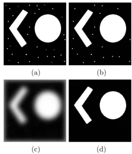
(a) (b)
(c) (d)
Figure 2: Simulation results. (a) Input image. (b) Simulation result of the “Small object remover” template. (c) Simulation result of the “Heat diffusion” template. (d)Simulation result of the proposed method (n= 5).
Figure 2 shows the input image and the simulation re- sults by the “Small object remover” template, the “ Heat diffusion ” template and the proposed method. The input image has many dots and graphics; circle, dogleg. In this simulation result, we define many dots as noise of the input image and 1st template is the “Small object remover” tem- plate and 2nd template is the “Heat diffusion” template. In Fig. 2(b), by using the “Small object remover” template, low dots are removed, however, general dots remain. On the other hand, in Fig. 2(c), all dots are removed, however, graphics are processed indistinctly by using the “Heat dif- fusion” template. In Fig. 2(d), all dots are removed and graphics are remain clearly. From the simulation results, the proposed method removed noise of the input image by applying the “Heat diffusion” template to the parts of dot.
4. Conclusions
In this study, we have proposed a new method of using two templates by the output values of neighboring cells.
The simulation results show that the proposed method is effective to remove noise of the input image. Therefore, the proposed method is effective in noise removal processing. In the future work, we will confirm that the proposed method is effective for another image processing.
平成29年度電気関係学会四国支部連合大会 講演論文集(2017愛媛大学) 2017 SHIKOKU-SECTION JOINT CONVENTION RECORD OF THE INSTITUTES OF ELECTRICAL AND RELATED ENGINEERS (EHIME)
1-8
8