Us i ng Wavel et Tr ans f or m f or SI Engi ne
Nobuo KURIHARA,Junichi S
UZUKI ,Yuuya SIRAYAMA ,
Jonathan BORG and Shigeru OHO
Abstract
This study examined the application of wavelet transforms to signal processing to improve the reliability of knock detection. It was expect ed that this method would make it possible not only to keep track of continuous knock vibrati ons,but also to detect vibrations occurring and disappearing instantaneously. For this the scal e‑spectrum comparison method was proposed as the method of knock detection. This method f ocuses on the components of resonant vibration that are specific to the engine,and compares t heir scale power spectra with each other in real time. A 4‑cycle gasoline engine was used for t he experiment. Cylinder pressure sensors and a vibration sensor were attached,and a comparat ive examination of the knock detection perfor- mance of the two signal processing methods,the conventional Fourier transform method and the proposed scale‑spectrum comparison method,was carried out. Data over the whole operating range of the engine was obtained,and the data s howed that it was possible to reduce both errors and mistakes as compared with the conventional method.
:Knocking Detection,Wavelet Transform,Scale‑spectrum Comparison Method, SI Engine
Introduction
In a spark‑ignition engine,knock control is widely used to produce optimum combus- tion,whatever the driving conditions or changes in fuel proper ties. Normally, a vibration sensor is at tached to the cylinder block and the timing of t he ignition is
controlled by detecting components of reso- nant vibrations in the vibration sensor signal, because these vibration components indicate the occurrence of knocki ng. The reliability of this method of knock det ection decreases as the engine speed or l oad increases,because of the increase in backgr ound noise. It is desirable to find a pr oposal for a detection method which minimi zes errors,which are erroneous detections of knocking,and misses, which are failures to detect knocking(this is called error‑free detect ion below).
Because the current knock detection method compares the combus tion character- istics of the past several times of combustion and the combustion char acteristics of the current time of combus tion, a delay in response occurs. Becaus e this detection method uses a Fourier transform,there is a
Received January 5,2007
Professor of Department of System & Infor- mation Engineering,Faculty of Engineer- ing,Hachinohe Institute of Technology,88‑
1,Myo,Hachinohe,Aomori 031‑8501,Japan Tel& Fax:+81‑178‑25‑8174,e‑mai l:kur- ihara@hi‑tech.ac.jp
Graduate Student of Doctor of Science Program in Mechani cal Engineering Sys- tems,Hachinohe Institute of Technology, 88‑1,Myo,Hachinohe,Aomori 031‑8501, Japan
Automotive Products Research Lab., Research& Development Division,Hitachi America,Ltd.
limit to the minimum numbers of waves necessary for detecti on,also reducing the sensitivity. These may caus e detection errors,and control per formance is not neces- sarily satisfactory for driving with frequent acceleration and decel eration.
To eliminate the delay in knock detec- tion,this study examines a method to detect a knock for each combus tion in an indepen- dent manner without using the past trend.
The sensor used was a conventional type,or a vibration sensor. It was decided to apply a wavelet transform,r ather than a conven- tional Fourier transform,to signal process- ing,because the former is thought to be advantageous in graspi ng the characteristics of local state changes . In the course of examining detection met hods in an experi- mental way,a basic method for signal proces- sing was first established using an in‑cylinder pressure sensor,and t hen its performance was compared to the convent ional method using a practical vibr ation sensor. As a result,a scale spectrum compar ison method using a wavelet transf orm was proposed,and a reduction of detecti on errors by this was confirmed by an engine experiment.
Knock control& experimental system
Knock control is a method that intention- ally generates minimal knocking and keeps its frequency properly. Knocki ng is detect- ed as resonant vibrations of in‑cylinder pres- sure,and vibrations that travel to a cylinder block are normally meas ured by an accelera- tion sensor. The occurrence of knocking is determined by using i ts vibrational energy.
In the conventional method of knock detec- tion,the power spectrum of a resonant fre-
quency specific to an engine is extracted through a bandpass f ilter or a digital filter (FFT). Ignition timing is gradually advanced. Then,when t he size of the fre- quency power spectrum exceeds a prescribed level,it is judged as the occurrence of knock- ing,and ignition timing is retarded. In knock control,this pr ocess is repeated,and ignition timing is advanced by t he average.
Therefore,the maximum torque is consis- tently obtained without the influence of fuel properties,operating condi tions,individual differences of engines ,differences among cylinders,etc. Resonant vibrations occur to some extent even in or dinary combustion caused by fire propagat ion,and have an influ- ence on knock detection as noises. For this reason,a method that l earns expected values from combustion data s everal times in the past and compares them i s adopted. This learning process causes detection delays,and worsens the performance of cont rol under acceleration. This study aims at eliminating the learning process of noi se levels and detecting knocking in one combustion stroke.
Knocking is a phenomenon that appears and vanishes in a shor t period of time in a combustion stroke. Ther efore, for the improvement of the sens itivity of detection,it is considered that a wavel et transform,which can grasp the character istics of local changes of state in comparison wi th a conventional Fourier transform,woul d be effective. In this study,the effect of the application of a wavelet transform i s experimentally examined. Figure 1 s hows the experimental system. A PC for anal ysis was installed in parallel with an engi ne control unit,and a spark plug that includes in‑cylinder pressure sensors and vibration s ensors were attached
to an engine. In‑cylinder pressure signals, vibration signals and crank angle signals were simultaneously meas ured through a 14‑
bit A/D converter. Because the frequencies of resonant vibrations t hat knock control covered were within 20 kHz,it was decided that the sampling peri od would be 10μs,and wavelet transforms wer e conducted for imported data using the same PC.
Scale‑spectrum comparison method
Six types that are shown in Figure 2 can be considered as resonant vibration modes of knocking. The circul ar form indicates a top view of a cylinder,and t he quadrangle indi- cates a side view of a cylinder. A1 and A2, which are primary circumferential modes, pair up with B1 and B2,which are secondary circumferential modes . In addition,C1 is a primary radial mode,and D1 i s a primary axial mode. The das hed line indicates the nodes of the oscillation of an air column,and
“+”and“−”respectively indicate the higher part and the lower par t of the pressure in a cylinder.
Figure 3 and Figure 4 show the measured
data that were obtained from experiments of an engine and the exampl e of the occurrence of knocking from the r esults of wavelet
Fig.1 Experimental system
Fig.2 Resonant‑vibration modes of knocking
Fig.3 Different modes in the same crank angle
Fig.4 Same mode in different crank angles and different mode i n the same com- bustion
transforms. In the upper part of Figure 3, the characteristics of knocking are grasped at 15 to 30 degrees of crank angles ATDC.
Scales are 4 to 7,and there is a power compo- nent like a white belt. As a result of calibra- tion,it was found that the power component corresponded to the res onant vibration mode C1. Also in the lower par t of Figure 3, knocking is grasped at 15 to 30 degrees of ATDC. However,the scales are 6 to 14,and the resonant vibration mode i s A1. In the lower part of Figure 3,t he resonant vibration mode C1 is grasped at 15 degrees of the crank angle ATDC,and the r esonant vibration mode A1 is grasped at 35 to 53 degrees of the crank angles ATDC. Fr om these results,the following findings are obt ained:
(1) Even at the same crank angle,dif- ferent resonant vibration modes occur.(in the upper part of Figur e 3 and the lower part of Figure 3)
(2) Even at different crank angles,the same resonant vibration mode occurs.(in the upper part of Figure 4 and t he lower right part of Figure 4)
(3) Even in the same combustion proc- ess,different resonant vibration modes occur depending on crank angl es.(in the lower left part of Figure 4 and t he lower right part of Figure 4)
(4) Plural resonant vibration modes do not simultaneously occur dominantly.(all)
From experiments with an engine,it was found that the identifi cation of various reso- nant vibration modes was important for knock detection. In par ticular,from many experimental results obt ained by the author and other persons,it i s judged that the fact that plural resonant vi bration modes do not simultaneously occur l ocally is a general
characteristic. In addition,the difference of resonant vibration modes can be discriminat- ed by scales. By using this finding,a method that can detect knocki ng in one combustion stroke without the l earning process is planned.
Figure 5 shows a new knock detection method that is a scale‑s pectrum comparison method. (1)Scale power spectra are deter- mined for resonant vibration modes. Here, resonant vibration modes of A1,B1,and C1 are shown. Correspondi ng scales are 12,8, and 6. (2)At a certain crank angle,scale power spectra that cor respond to resonant vibration modes A1,B1,and C1 are compared mutually. The detail s are as follows. The engine is started at ever y stroke of combus- tion. First,depending on crank angles,in‑
cylinder pressure signals are sampled at a high speed from 0 to 60 degr ees of crank angles ATDC,which ar e regarded as the domain where knocki ng occurs. Then, filtering is conducted in the frequency domain from 5 to 20 kHz. Next ,depending on crank angles,scale power spect ra P ,P ,and P are determined at scales a of 12,8,and 6 that correspond to resonant vibration modes A1, B1,and C1. Then,the crank angle zone A that corresponds to l arge P is determined.
Fig.5 Scale‑spectrum comparison method (proposed)
In the crank angle zone A,P ,P ,and ,that is,the average values of P ,P ,and P ,are determined. The r atio of P and the sum of P and P is determined,and the result is defined as t he index P that indicates knock intens ity. In the same man- ner,P and P are also determined. If one of the two knock indexes P ,P ,and P exceeded the threshold value P ,it is judged that knocking occurr ed. If all the knock indexes P ,P ,and P do not exceed the threshold value P ,it i s judged that knocking did not occur.
Knock detection in one combustion
Figure 6 to Figure 8 show the examples of experimental resul ts where knock detec- tion was conducted by using the proposed scale‑spectrum compar ison method. The operating condition is 2, 000 rpm at a constant state. A threshold val ue for the judgment of knocking is set to pr event wrong judgment arising from the variat ion of combustion,and P =1.5 was set here. I n Figure 6,the knock indexes P ,P ,and P were sequentially compared with,P and P >P was judged as the occurrence of knocki ng. Similarly in Figure 7,P >P was judged as the occur- rence of knocking. Figure 8 shows an exam-
ple where it was judged that no knocking had occurred,because the knock indexes P ,P , and P did not exceed the threshold value
. From these results,it was proved that knocking could be det ected in one combus- tion stroke.
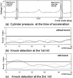
Figure 9 shows an example of experi- mental results under acceleration. Figure 9 (a)is a waveform of in‑cylinder pressure.
Acceleration was started from 850 rpm at the 1 hill,and the speed at the 3 hill is 3,000 rpm. Figure 9(b)and(c)s how the results where the scale‑spect rum comparison method was applied to the 1 hill and the 3 hill. In Figure 9(b), knocking was not detected. However,i n Figure 10(c),knock- ing was detected in the range of crank angles from 9 to 13 degrees. Fr om these results,it was proved that knocki ng could be detected also under accelerati on by using the same threshold value as at a constant state.
Fig.6 Example detecting knock with mode C
Fig.7 Example detecting knock with mode A
Fig.8 Example not detecting knock
Reducing detection errors
The current engine uses not an in‑cyclin- der pressure sensor,but a vibration sensor. Therefore, the S/N ratio of the signal decreases and detection errors occur. It was examined whether the s cale spectrum com- parison method has the effect of reducing such detection errors.
For judgment of the occurrence of knocking,the results obt ained using the in
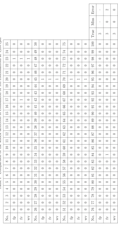
‑cylinder pressure sensor were used as a reference. The signal of the vibration sen- sor was transformed into a Fourier trans- form and compared with this reference. The results of this compar ison and the results obtained using the scal e spectrum compari- son value(knock index)are shown in Table 1. The judgment resul ts shown here concern the data obtained for 100 consecutive times of combustion at 1,200 and 5, 000 rpm,respec- tively.
Detection errors were defined here as follows:
True:Occurrence of knocking judged according to the in‑cyl inder pressure sensor signal and occurrence of knocki ng judged according to the vibrat ion sensor signal
Miss:Occurrence of knocki ng judged based on the in‑cylinder pressure sensor sig- nal,but absence of knocking judged accord- ing to the vibration sensor signal
Error:Absence of knocki ng judged according to the in‑cyl inder pressure sensor signal,but occurrence of knocki ng judged according to the vibrat ion sensor signal
Table 1 shows exampl es of knock detec- tion at 1,200 rpm,using the in‑cylinder pres- sure signal.
Where
f p:Fourier spectrum method using the in‑cylinder pressure s ensor signal(used as a reference of knock judgment )
fv:Fourier spectrum method using the vibration sensor signal(cur rent method)
wv:Scale spectrum comparison method using the vibration sens or signal(proposed method),“1”:occurrence of knocking,“0”:
absence of knocking.
Knocking was detected 3 times per 100 combustions at 1,200 r pm. For these
Fig.9 Knock detection at the time of acceler- ation
Fig.10 Trend of frequency‑spectrum of in‑
cylinder pressure signals
Table 1 Comparison of the knock detection in combustion of 100 continuations at 1,200 rpm No.1 2 3 4 5 6 7 8 9 10 11 12 13 14 15 16 17 18 19 20 21 22 23 24 25 fp 0 0 0 0 0 0 0 0 0 0 0 0 0 0 0 0 0 0 0 0 0 0 1 0 0 fv 0 0 0 0 0 0 0 0 0 0 0 0 0 0 0 0 1 0 0 0 0 0 1 0 0 wv 0 0 0 0 0 0 0 0 0 0 0 0 0 0 0 0 0 0 0 0 0 0 1 0 0 No.26 27 28 29 30 31 32 33 34 35 36 37 38 39 40 41 42 43 44 45 46 47 48 49 50 fp 0 0 0 0 0 0 0 0 0 0 0 0 0 0 0 0 0 0 0 1 0 0 0 0 0 fv 0 0 0 0 0 0 0 0 0 0 0 0 0 0 0 0 0 0 0 1 0 0 0 0 0 wv 0 0 0 0 0 0 0 0 0 0 0 0 0 0 0 0 0 0 0 1 0 0 0 0 0 No.51 52 53 54 55 56 57 58 59 60 61 62 63 64 65 66 67 68 69 70 71 72 73 74 75 fp 0 0 0 0 0 0 0 0 0 0 0 0 0 0 0 0 0 0 0 1 0 0 0 0 0 fv 0 0 0 0 0 0 0 0 0 0 0 0 0 0 0 0 0 0 0 1 0 0 0 0 0 wv 0 0 0 0 0 0 0 0 0 0 0 0 0 0 0 0 0 0 0 1 0 0 0 0 0 No.76 77 78 79 80 81 82 83 84 85 86 87 88 89 90 91 92 93 94 95 96 97 98 99 100 True Miss Error fp 0 0 0 0 0 0 0 0 0 0 0 0 0 0 0 0 0 0 0 0 0 0 0 0 0 3‑‑ fv 0 0 0 0 0 0 0 0 1 0 0 0 0 0 0 0 0 0 0 0 0 0 0 0 0 3 0 2 wv 0 0 0 0 0 0 0 0 0 0 0 0 0 0 0 0 0 0 0 0 0 0 0 0 0 3 0 0
knocks,the results(fv)of the Fourier trans- form using the vibration sensor signal caused no Miss judgments,but 2 Er rors. By the method of applying the scale spectrum com- parison method,the results(wv)were im- proved to no Miss judgments and no Errors at 1200 rpm.
Conclusions
Knock control is applied to combustion optimization of gasol ine engines,and this study strived for perf ormance improvement of knock control. In convent ional knock detection,there is a del ay due to learning the past combustions,and t his lowers the control performance during accel erating driving.
Based on engine experiments,this study (1) found that multiple resonant vibra- tion modes do not occur simultaneously.
(2) proposed a scale spectrum compari-
son method using a wavelet transform.
(3) found that the scale spectrum com- parison method can detect a knock in one combustion,and that i t can also be applied during accelerating dr iving.
(4) confirmed that detection errors can be reduced by applyi ng the scale spectrum comparison method t o a practical vibration sensor.
References
1. M.Kaneyasu,N.Kurihara,et al.,Engine knock detection us ing multi‑spectrum method,SAE paper 920702(1992)
2. D.Scholl,and C.Davis,et al.,The volume acoustic modes of s park‑ignited internal combustion chambers ,SAE paper 980893 (1998)
3. N.Kurihara,J.Fu,et al.,Quick Detection of Knocking Combusti on Using Wavelet Transform for Spark‑I gnition(SI)Engine, Proc.12th Int.Congress on Sound and Vibration,ICSV12,Paper No.717(2005)