• 検索結果がありません。

ALL-ATOM MOLECULAR MODELING AND DYNAMICS SIMULATION OF TROPOCOLLAGEN STRUCTURES WITH CROSS-LINKING

N/A
N/A
Protected

Academic year: 2021

シェア "ALL-ATOM MOLECULAR MODELING AND DYNAMICS SIMULATION OF TROPOCOLLAGEN STRUCTURES WITH CROSS-LINKING"

Copied!
12
0
0

読み込み中.... (全文を見る)

全文

(1)

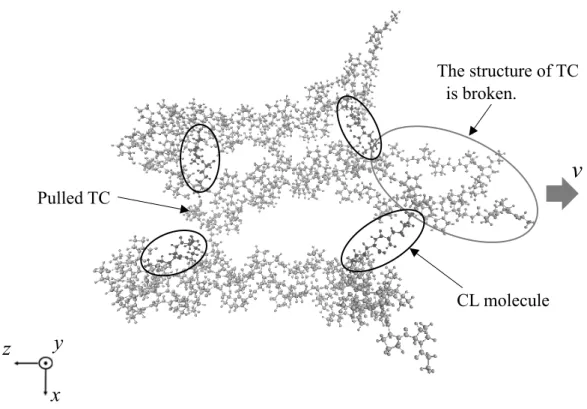
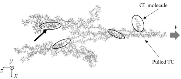
SIMULATION OF TROPOCOLLAGEN STRUCTURES WITH CROSS‑LINKING

著者 Suzuki Ryosuke, Saitoh Ken‑ichi, Sato

Tomohiro, Takuma Masanori, Takahashi Yoshimasa journal or

publication title

Science and technology reports of Kansai University = 関西大学理工学研究報告

volume 63

page range 1‑11

year 2021‑03‑20

URL http://doi.org/10.32286/00022958

(2)

ALL - ATOM MOLECULAR MODELING AND DYNAMICS  SIMULATION OF TROPOCOLLAGEN STRUCTURES 

 WITH CROSS - LINKING

Ryosuke Suzuki,

1

 Ken - ichi Saitoh,

2*

 Tomohiro Sato

2

  Masanori Takuma

2

, and Yoshimasa Takahashi

2


(Received November 26, 2020)

Abstract

Collagen is the most abundant protein in humans and animals, and it is currently being applied to the development of novel materials used in medical devices. In order to improve the performance and usability of such devices, understanding the strength of collagen is key. The basic structural unit of collagen is tropocollagen (TC), which are nanometer-sized rods composed of characteristic triple helices of peptide molecules. As TC is too small to be evaluated experimentally, computer modeling and simulation using molecular dynamics ( MD ) are effective in its study. There are numerous cross - linked structures between TC molecules that are considered to have major effects on its mechanical properties, including strength and ductility. In this study, an all-atom model for MD computation is constructed in which three TC molecules are arranged in parallel together with some improvised cross- linking (CL) molecules. A simulation of the tensile test is conducted by pulling one of the molecules using the steered molecular dynamics ( SMD ) method in order to investigate the influence of CL molecules in the deformation process of TC molecules. The results revealed that the model with CL molecules requires greater load than the model without CL molecules until the TC molecules are removed. This study demonstrates that CL molecules play a major but microscopic role in increasing the strength of collagen.

1. Introduction

Collagen is a protein that exists in most multicellular organisms and is found, for example, in the skin, blood vessels, and many organs. In tissue engineering, collagen appears to have good compatibility with original human tissues and no fatal rejection symptoms are observed when it is placed into the body short or long term. It is for this reason that collagen is preferentially employed as a novel material in medical devices such as artificial blood vessels and artificial skin, and in cartilage regeneration in joints

(1)

. Collagen is a kind of biological polymer material ( biopolymer ) , and its required strength and reliability are relatively high.

As collagen ' s properties can vary depending on the intended use, it is necessary to evaluate its key mechanical properties to enable its use as a reliable biomaterial.

On a microscopic scale, cross - linking structures connect collagen elements ( molecules ) , 1 Graduate School of Science and Engineering, Kansai University, Suita, Osaka, Japan

2 Department of Mechanical Engineering, Faculty of Engineering Science, Kansai University, Suita, Osaka, Japan

*Corresponding author: Ken-ichi Saitoh

Email: [email protected], Tel: +81-6-6368-1121 ext. 6371, Fax: +81-6-6388-8785

(3)

and have a major influence on the mechanical properties of collagen as a whole. Although the mechanics and dynamics of collagen microstructures have previously been studied, it remains unknown how elements of collagen respond to severe situations such as high mechanical stress. Currently, thanks to physical theories, instead of conducting difficult nanoscale experiments, atomistic modeling and simulations can provide key insights into the structure and dynamics of these microscale substances. Mechanical evaluation by computer simulation is capable of investigating the direct response of the basic elements that make up collagen. It is generally recognized that tropocollagens ( TCs ) are a very small ( i.e., nanometer - sized ) constituent of collagen that are composed of complicated hierarchical structures. Previous studies have compiled extensive results from MD simulations of TCs. Polymer materials are usually strengthened by CL structures, and some studies report the strengthening effect of CL in collagen

(2)

. The tensile strain value observed in TC structures tends to increase its limit against longitudinal load, and larger tensile force should be required for complete breakage due to CL structures

2)3)

. Most of these studies examined only one or two TC molecules, however. On the larger scale, actual collagen consists of great numbers of TC molecules and CL molecules, and it is thus important to aim to simulate an aggregate of TCs attaching together by the CL mechanism using larger - scale models. In this study, a sophisticated simulation model is considered in which improvised but distinctive CL molecules ( composed of lysine ) are located between TCs, and tensile test simulations are conducted. In discussing these results, we mainly consider the effect of CL structures and their behavior on the mechanical properties of total TC structures.

2. Structure of Tropocollagen

Tropocollagen ( TC ) is the smallest basic structural unit of collagen; it is rod - shaped and has a diameter of approximately 1 . 5 nm and a length of approximately 300 nm. One TC molecule is composed of three polypeptide chains that are coiled around each other to form a right - handed spiral. The TC molecule is characterized by the unique structure of its atomic - level triple helix. Each polypeptide chain is made of a polymerized structure of amino acids in sequence, such as glycine ( Gly ) , proline ( Pro ) , hydroxyproline ( Hyp ) , and so on

4)

. Figure 1 shows the structure of a single TC in which the skeleton of the protein secondary structure found along the main carbon atoms is displayed in a tube motif view to make it easier to view the state of the triple helix.

Polypeptide chains

x y z

Fig.  1 All - atom modeling of TC ( tube motif view )

(4)

3 . Computational Details and Simulation Models

For MD analysis, we use the versatile NAMD ( NAnoscale Molecular Dynamics program )

(5)

software, which offers good parallelization efficiency and is suitable for large - scale calculation.

We also use a force field called CHARMM ( CHARMM 22)

6)

, which is specialized for biomolecules. In this study, a virtual testing method framework called steered molecular dynamics ( SMD ) , which is applicable to materials' dynamical evaluation, is utilized. This method makes it possible to deform the protein structure in the desired direction during the MD simulation run so one can clarify the intact dynamics of structural changes and can estimate the mechanical properties of the protein at the atomic level. The selected atoms to be pulled are defined as SMD atoms, and the entire structure is pulled by giving a constant velocity to virtual atoms that are individually bound to SMD atoms through a virtual spring

(5)

. We need to adjust the spring constant so that deformation of the structure is tested adequately.

In this study, as shown in Fig. 2 , a CL is prepared from two lysine molecules ( one of the ordinary amino acids ) molecules that are covalently bonded to each other and it is placed at points in the gap between TC molecules. Since both the realistic molecular structure and the bonding mechanism of CL remain ambiguous, it is better to use this improvised modeling at this point. In this way, a relatively local and intense intermolecular bond is generated between CL and TC molecules. In reality, however, considering that the CL structure is made by a covalent bond ( giving a stronger bond than the intermolecular one )

7)

, the bond strength occurring in the CL molecule should be somewhat increased. This is realized by increasing the electric charge of the hydrogen atoms located at the end of the present CL molecule. The electric charges of specified hydrogen atoms marked with circles in Fig. 2 are modified. A suitable factor for the change in the electric charge will be sought later in Sec. 4 .

to TC

to TC

y

x z

Fig.  2  Image of the CL molecule

(5)

Figure 3 shows a schematic of the simulation model for tensile loading. Figure 4 shows an actual atomic configuration in the initial state ( before loading ) by all - atom presentation. Table 1 shows the simulation conditions. All of the TC molecules are arranged parallel to the z- axis and on the same xz plane, as shown in Fig. 3 . One of the TC molecules in the center is pulled in the minus z (-z) direction, but the other two TC molecules are constrained at the leftmost part. Technically speaking, the carbon atoms at the rightmost or leftmost end of all three polypeptide chains in the TCs are assigned as SMD atoms, and they are pulled with constant velocity in the minus z (-z) direction or fixed in the space ( kept at zero velocity ) . Two or four CL molecules are inserted in the gap between these TC molecules relatively near the end region.

Hereafter, the model with two CL molecules will be referred to as “ 2 Cross - Links” and that with four CL molecules as “ 4 Cross - Links.” In addition, for comparison, the models without CL molecules will be referred to as “No Cross - Links.” An initial distance, d , between TCs is set, as shown in Fig. 3 , so that TCs can stick to each other by intermolecular or Coulomb force during structural relaxation calculation. Since CL molecules are included in the 2 Cross - Links and 4 Cross - Links models, the initial distance is set larger than that in the No Cross - Links model. In the 2 Cross - Links model, the positions of two CL molecules are chosen as shown in the hollow rectangles in Fig. 3 . Tensile simulations using these models are conducted to examine the effect of CL molecules on the deformation behavior. In addition, the nominal strain of the total TC structure, ε , can be calculated by the product of the tensile strain rate and the elapsed time, because a constant stretching rate occurs between SMD atoms located on opposite sides. Force exerted on the structure is estimated from the summation of reaction forces at moving SMD atoms, and nominal stress is obtained from dividing the force by the initial cross - section area occupied by TC molecules. The pulling velocity is v = 5 or 10 m/s. In order to avoid the congestion of atomic positions in different molecules due to their thermal vibration, the system temperature is kept at 1 K. Simulations were checked from 1 K to 310 K ( vital temperature ) , and the temperature condition of 1 K was found to sufficiently represent the basic mechanism of TC and CL molecules. Depending on deformation velocities, viscoelastic behavior may appear, but overly slow tensile speed is not allowed in MD simulation due to the small time increments. Therefore, adequate pulling velocities are chosen by considering previous simulations

(8)

and computational costs.

z y

x y x

z

Fig.  3  Schematic of the tensile simulation model (4 Cross - Links )

(6)

TC

CL molecule

x

z y

Fig. 4 Simulation model visualized by all-atom presentation

Table 1 Calculation conditions for tensile simulation

No Cross - Links 2 Cross - Links 4 Cross - Links

Number of atoms in the model 2862 (954 × 3)

Number of atoms in the CL molecule 0 92 (46 × 2) 184 (46 × 4)

Distance between adjacent TCs d [nm] 0 . 76 1 . 1 1 . 4

Length of TC L      [nm] 7 . 5

Spring constant k  [kcal/mol/Å

2

] 10

Pulling velocity v     [m/s] 5, 10

Temperature  T     [K] 1

4. Determination of Factor of Electron Charge in Cross-Linking Molecules  4.1 Calculation setup 

Before the main simulation, it is preliminarily determined how much the electric charge of

designated hydrogen atoms in CL molecules should be increased to approximate the

interaction in the real CL mechanism as closely as possible. Technically, the electric charge

can be changed simply by editing the corresponding part of the protein structure file ( PSF )

9)

of the CL molecule, which is required for MD simulation and describes the information of the

included atoms and the bond properties between them. The electric charge is stepwise

changed to 1 . 5 , 2 . 0 and 3 . 0 times higher compared with the original one. Tensile simulation is

performed using the 4 Cross - Links model as explained, and the electric charge of the

hydrogen atom that has been modified will be determined from viewing the behavior of the

TC model when the load is being applied. Table 2 shows the calculation conditions.

(7)

Table 2 Calculation conditions for determining the value of electric charge

Original 1.5 times 2.0 times 3.0 times Number of atoms in the model TC… 2862 (954 × 3) , CL molecules… 184 (46 × 4)

Length of TC L    [nm] 7 . 5

Distance between adjacent TCs d [nm] 1 . 4

Spring constant k  [kcal/mol/Å

2

] 10

Pulling velocity v   [m/s] 10

Temperature   T   [K] 1 . 0

4.2 Results   

The stress - strain curves obtained from the tensile simulation are shown in Fig. 5 . Figure 5 shows that the maximum stress increases as the modified electric charge increases. Until nominal strain reaches around ε = 0 . 2 , however, there is not much difference between results for different charges. The appearance of the model under each condition at the beginning of tensile loading is shown in Figs. 6( a ) , 6( b ) , and 6( c ) . As shown in Fig. 6( c ) , only in the case of the 3 times larger electric charge is the structure of the middle TC molecule broken into individual peptide chains, as indicated by an oval in the figure. Therefore, the interaction offered by the CL molecule with 3 times larger electric charges is too strong to apply to subsequent simulation and is inappropriate. Thus, we determined that the CL molecule with a 2 times larger electric charge will be the best among these conditions and will be used for subsequent simulations.

Fig.  5  Change in stress among the different electric charges of hydrogen

atoms in CL molecules

(8)

v

Pulled TC

CL molecule x

z y

Fig.  6( a )  Snapshot obtained by tensile simulation for 1 . 5 times larger electric      charge of hydrogen atoms in CL molecules

v

Pulled TC

CL molecule x

z y

Fig.  6( b )  Snapshot obtained by tensile simulation for 2 . 0 times larger electric

     charge of hydrogen atoms in CL molecules

(9)

v

Pulled TC

CL molecule

z y

x

The structure of TC is broken.

Fig.  6( c )  Snapshot obtained by tensile simulation for 3 . 0 times larger electric      charge of hydrogen atoms in CL molecules

5 . Results and Discussion

Figure 7 shows the stress - strain curves obtained from the tensile simulation, and Figs. 8 and 9 show the atomic configuration at points A and B denoted by arrows in Fig. 7 . CL molecules are surrounded by ovals for easy viewing. It is evident that the nominal stress increases almost monotonically up to around the strain value of ε = 0 . 34 ( at point A of Fig.

7) in the 4 Cross - Links model, with the pulling velocity of v = 10 m/s. Figure 8 shows that all of the CL molecules are neatly and strongly bound to two neighbor TCs as if they are making a bridge. This is why the stress continues to increase in the period shown in Fig. 7 . Subsequently, the stress drops abruptly when the CL molecule takes TC molecules off, as indicated by the thick arrow in Fig. 9 ( at point B in Fig. 7) . Since any CL molecule can play the role of connecting the fixed and the pulled TCs in this way, it resists separating the two neighboring TC molecules, and the fluctuation of the stress tends to be large in this situation.

Meanwhile, in the No Cross - Links model, small vibration of the stress is frequently observed because direct and uniform hydrogen bonds between TCs occur there and are gradually lost as TCs are sliding. The stress in the No Cross - Links model is generally smaller than that in the 4 Cross - Links model. These findings for the results of v = 10 m/s are independent of deformation velocity because the results of v = 5 m/s exhibit the same tendency. Table 3 shows the maximum stress in the strain range from 0 to 0 . 5 , comparing velocity conditions.

The table shows that the maximum stress increases as the number of CL molecules increases.

In sum, these results suggest that the bonding forces locally produced between the CL and

TC molecules have a critical effect on the strength or resistance against tensile deformation in

collagen.

(10)

A B

Fig.  7  Stress - strain curves for 4 Cross - Links and No Cross - Links models

Pulled TC

CL molecule

v

z y

x

Fig. 8 Snapshot obtained by tensile simulation (at point A in Fig. 7, v = 10 m/s)

(11)

v

Pulled TC CL molecule

z y

x Fig.  9  Snapshot obtained by tensile simulation ( at point B in Fig. 7 , v = 10 m/s )

Table 3 Relationship between the number of CL molecules and the maximum value of stress

Model name Maximum value of stress [MPa]

No Cross - Links ( v = 5 m/s ) 217 . 02

2 Cross - Links ( v = 5 m/s ) 301 . 84

4 Cross - Links ( v = 5 m/s ) 633 . 18

No Cross-Links (v = 10 m/s) 256.22

2 Cross - Links ( v = 10 m/s ) 327 . 42

4 Cross - Links ( v = 10 m/s ) 699 . 71

6.  Conclusion

In this study, a simulation model of microscopic TC was constructed on the basis of an all - atom modeling methodology framework. MD simulations were conducted to investigate the effect of CL molecules on the mechanical response of TC specimens in tensile loading. It was confirmed that CL structures behave as local and strong bonds between TC molecules and resist against the fatal breakage of specimens. We believe that this microscopic response is primarily responsible for the tensile strength of collagen.

References

1 ) M. Tanihara. Production and Application of Collagen. CMC Publishing Co., 31-39 , 204-224 , (2015) , (in Japanese).

2) S.G.M. Uzel, M.J. Buehler, Molecular Structure, Mechanical Behavior and Failure Mechanism of the C - Terminal Cross - Link Domain in Type I Collagen, J. Mechanical Behavior of Biomedical Materials, 4 , 153-161 , (2011) .

3 ) H. Ghodsi, K. Darvish, Characterization of the Viscoelastic Behavior of a Simplified Collagen

Micro-Fibril based on Molecular Dynamics Simulations, J. Mechanical Behavior of Biomedical

(12)

Material, 4, 153-161, (2011).

4 ) K. Okuyama, Structure of Collagen, Nihon Kessyou Gakkaisi, 54 , 263-269 , (2012) , ( in Japanese ) . 5 ) J.C. Phillips et al., Scalable Molecular Dynamics with NAMD, J. Computational Chemistry, 26 , 16 ,

1781-1802 , (2004) .

6) A.D. Mackerell et al., All-Atom Empirical Potential for Molecular Modeling Dynamics Studies of Proteins, J. Physical Chemistry, 102, 3586-3616, (1998).

7 ) L. Knott, A.J. Bailey, Collagen Cross - Links in Mineralizing Tissues: A Review of Their Chemistry, Function, and Clinical Relevance, Bone, 22 , 181-187 , (1998) .

8 ) A. Gautieri et al., Intermolecular Slip Mechanism in Tropocollagen Nanofibrils, J. Materials Research, 100 , 921-925 , (2009) .

9) I. Tim. et al., NAMD TUTORIAL, University of Illinois, 92-94, (2017).

  http://www.ks.uiuc.edu/Training/Tutorials/

Fig.  1  All - atom modeling of TC  ( tube motif view )
Fig.  2  Image of the CL molecule
Figure  3  shows a schematic of the simulation model for tensile loading. Figure  4  shows an  actual atomic configuration in the initial state  ( before loading )  by all - atom presentation
Fig. 4 Simulation model visualized by all-atom presentation
+6

参照

関連したドキュメント

The inclusion of the cell shedding mechanism leads to modification of the boundary conditions employed in the model of Ward and King (199910) and it will be

[11] Karsai J., On the asymptotic behaviour of solution of second order linear differential equations with small damping, Acta Math. 61

Keywords: continuous time random walk, Brownian motion, collision time, skew Young tableaux, tandem queue.. AMS 2000 Subject Classification: Primary:

Kilbas; Conditions of the existence of a classical solution of a Cauchy type problem for the diffusion equation with the Riemann-Liouville partial derivative, Differential Equations,

Maria Cecilia Zanardi, São Paulo State University (UNESP), Guaratinguetá, 12516-410 São Paulo,

Debreu’s Theorem ([1]) says that every n-component additive conjoint structure can be embedded into (( R ) n i=1 ,. In the introdution, the differences between the analytical and

Then it follows immediately from a suitable version of “Hensel’s Lemma” [cf., e.g., the argument of [4], Lemma 2.1] that S may be obtained, as the notation suggests, as the m A

To derive a weak formulation of (1.1)–(1.8), we first assume that the functions v, p, θ and c are a classical solution of our problem. 33]) and substitute the Neumann boundary